Can And An Urging Member Therefor
LEIZER; Tal ; et al.
U.S. patent application number 16/729900 was filed with the patent office on 2020-07-02 for can and an urging member therefor. The applicant listed for this patent is Caniel Industries A. T. G. Ltd.. Invention is credited to Offer ABRAMOVITCH, Arie GABAY, Pavel GORODNITSKY, Tal LEIZER, Menahem SALAN, Lior YEMINI.
| Application Number | 20200207504 16/729900 |
| Document ID | / |
| Family ID | 69063646 |
| Filed Date | 2020-07-02 |


View All Diagrams
| United States Patent Application | 20200207504 |
| Kind Code | A1 |
| LEIZER; Tal ; et al. | July 2, 2020 |
CAN AND AN URGING MEMBER THEREFOR
Abstract
An urging member and a can using such member as a base of the can, are provided for containing in the can a product comprising solid component(s) and liquid component(s). The can with the product, at least in a ready-for-sale state, comprises a lid hermetically sealing the can and at least partially openable to allow at least partial removal of the product, the base opposite the lid constituted by the member and a side wall extending therebetween. The member is for urging inwardly by a user applying, at least in use of the can when the lid has been at least partially opened, an urging force, allowing changing the state of the member between a first state, in which the can has a first contained volume and a second, deformed state, in which the can has a second contained volume smaller than the first contained volume.
| Inventors: | LEIZER; Tal; (Zikhron Ya'akov, IL) ; GABAY; Arie; (Ra'anana, IL) ; YEMINI; Lior; (Shoham, IL) ; ABRAMOVITCH; Offer; (Givat Ada, IL) ; SALAN; Menahem; (Rishon Lezion, IL) ; GORODNITSKY; Pavel; (Modiin, IL) | ||||||||||
| Applicant: |
|
||||||||||
|---|---|---|---|---|---|---|---|---|---|---|---|
| Family ID: | 69063646 | ||||||||||
| Appl. No.: | 16/729900 | ||||||||||
| Filed: | December 30, 2019 |
| Current U.S. Class: | 1/1 |
| Current CPC Class: | B65D 2517/5013 20130101; B65D 17/4011 20180101; B65D 2517/0083 20130101; B65D 17/502 20130101; B65D 81/261 20130101; B65D 77/2024 20130101; B65D 83/0094 20130101; B65D 2517/0049 20130101; B65D 17/4012 20180101; B65D 1/32 20130101; B65D 2517/0061 20130101; B65D 2517/0016 20130101; B65D 2517/0082 20130101; B65D 1/20 20130101; B65D 81/22 20130101; B65D 17/02 20130101; B65D 79/005 20130101; B65D 17/34 20180101; B65D 17/04 20130101 |
| International Class: | B65D 1/32 20060101 B65D001/32; B65D 81/26 20060101 B65D081/26; B65D 1/20 20060101 B65D001/20; B65D 83/00 20060101 B65D083/00 |
Foreign Application Data
| Date | Code | Application Number |
|---|---|---|
| Dec 30, 2018 | IL | 264029 |
| Sep 1, 2019 | IL | 269046 |
Claims
1. An urging member for use as a base of a can containing a product comprising at least one solid component and at least one liquid component, the can with the product when in a ready-for-sale state having in addition to the base, a side wall and a lid hermetically sealing the can and at least partially openable to allow at least partial removal of the product from the can, the urging member having a body comprising a metal material and having a peripheral edge lying in a reference plane, said body being configured to be urged in a pre-determined direction, when the peripheral edge is fixedly held in place, by a user applying to the body at a location spaced from the peripheral edge an urging force, thereby changing the state of the urging member from a first state to a second, deformed state, both states being characterized by a volume contained between (a) the body, (b) a first imaginary surface parallel to the reference plane and spaced therefrom in said direction to a distance greater than that between the reference plane and any point of said body in the deformed state, and (c) a second imaginary surface perpendicular to the first imaginary surface and extending between the first imaginary surface and said peripheral edge; said volume being a first volume in the first state of the body and a second, reduced volume smaller than the first volume in the second, deformed state of the body; the urging member being configured to be fixedly connected at its peripheral edge to the side wall of the can at its end opposite to that at which the lid is to be connected, with the pre-determined urging direction directed towards the inside of the can, so as to constitute a base in the can with the product in the ready-for-sale state, the base being configured, at least in use of the can when the lid has been at least partially opened, to be urged inwardly by a user applying thereto said urging force, thereby changing the volume of the can between a first volume of the can in the first state of the urging member and a second, reduced volume of the can smaller than the first volume in the second, deformed state of the urging member.
2. The urging member according to claim 1, wherein said urging member when in the can with the product in the ready-for-sale state, is configured to be brought into a maximally deformed state, at which the can has a minimal contained volume, only after the lid has been at least partially opened.
3. The urging member according to claim 1, wherein the body is produced separately and is configured to be integrally mounted to the side wall at the peripheral edge thereof.
4. The urging member according to claim 1, wherein the urging member is configured to be repeatedly elastically deformed between the first state and the second state upon the corresponding application and release of said urging force by a user.
5. The urging member according to claim 4, wherein the urging member is configured to be elastically deformed between the first and second states by the respective application and release of the urging force a number of times, said number being at least more than twenty.
6. The urging member according to claim 1, wherein the urging member has a configuration, which allows the urging of the urging member by a user from the first state to the second state, the metal from which the body is made being sufficiently stiff to prevent the urging of the urging member if this member of the same thickness were to be free of said configuration.
7. The urging member according to claim 1, wherein: the body further comprises a central area and an intermediate area extending between the central area and the peripheral edge; the orientation of the intermediate area relative to the central area and to the peripheral edge is different in the first and second states of the urging member, and optionally in the first state the intermediate area extends from the peripheral edge towards an exterior of the can and in the second, deformed state of the urging member, the intermediate area extends towards an interior of the can.
8. The urging member according to claim 7, wherein in the initial state of the urging member, the body of the urging member is generally convex in shape, and in the deformed state of the urging member, the body of the urging member is generally concave in shape.
9. The urging member according to claim 7, wherein the shape of the central area is configured to be maintained unchanged between the first and second states of the urging member.
10. The urging member according to claim 7, wherein the configuration of the body is such that the intermediate area deforms preferentially to the central area under the application by the user of said urging force to the urging member.
11. The urging member according to claim 1, wherein the ready-for-sale state of the can is a state which the can with the product has after having undergone the entire manufacturing process.
12. The urging member according to claim 11, wherein during said process, the can with the product is configured to withstand pressure differential between the inside and outside of the can of 150 KPa without buckling.
13. The urging member according to claim 1, wherein a ratio between the reduced volume and the initial volume of the can is at least between 0.5-0.95.
14. The urging member according to claim 1, wherein the can in its ready-for-sale state has an exterior surface bearing instructions for a user to (a) open a portion of the lid to an extent sufficient for the liquid component to be pushed therethrough while preventing the solid component from leaving the can, (b) orient the can so that the open portion of the lid faces at least partially downwards, and (c) apply and release an urging force on the base of the can repeatedly.
15. An urging member for use as a base of a can, the can with the product when in a ready-for-sale state having in addition to the base a side wall and a lid, the urging member comprising a body comprising metal and having a peripheral edge lying in a reference plane, said body being configured to be repeatedly elastically deformed, when the peripheral edge is fixedly held in place, by a user repeatedly applying to the body and releasing an urging force, thereby repeatedly changing the state of the urging member between a first state and a second, deformed state, both states being characterized by a volume contained between (a) the body, (b) a first imaginary surface parallel to the reference plane and spaced therefrom in said direction to a distance greater than that between the reference plane and any point of said body in the deformed state, and (c) a second imaginary surface perpendicular to the first imaginary surface and extending between the first imaginary surface and said peripheral edge; said volume being a first volume in the first state of the body and a reduced volume smaller than the first volume in the second deformed state of the body; the urging member being configured to be fixedly mounted to the side wall of the can with the pre-determined urging direction directed towards the inside of the can so as to allow it, at least in use of the can when the lid has been at least partially opened, to be deformed inwardly and elastically returned back, between the first and the second states, respectively, in a repeated manner upon the respective repeated application and release of said urging force, resulting in a corresponding change of the contained volume of the can.
16. A can for containing a product comprising at least one solid component and at least one liquid component, the can with the product at least in a ready-for-sale state comprising a lid hermetically sealing the can and at least partially openable to allow at least partial removal of the product from the can, a base opposite the lid and a side wall extending therebetween; the base being in the form of a body comprising a metal material and constituting an urging member configured to be urged inwardly by a user applying thereto, at least in use of the can when the lid has been at least partially opened, an urging force, thereby allowing changing by the user the state of the urging member between a first state, in which the can has a first contained volume and a second, deformed state, in which the can has a second contained volume smaller than the first contained volume.
17. The can according to claim 16, wherein the base has a peripheral edge, along which the body is fixedly connected to the side wall.
18. The can according to claim 16, wherein the urging member is configured to be repeatedly deformed between the first state and the second state upon the corresponding application and release of said urging force by a user to cause the corresponding repeated change of the contained volume of the can.
19. The can according to claim 18, wherein the urging member is configured to be elastically deformed between the first and second states by the respective application and release of the urging force a number of times, said number being more than twenty.
20. The can according to claim 16, wherein the urging member has a configuration, which allows the urging of the urging member by the user from the first state to the second state, the metal from which the body is made being sufficiently stiff to prevent the urging of the urging member if this member of the same thickness were to be free of said configuration.
Description
TECHNOLOGICAL FIELD
[0001] The presently disclosure relates to a can for containing a product comprising at least one solid component and at least one liquid component with an urging member and/or a lid, configured to facilitate the removal of at least some of the liquid component prior to the removal of the solid component.
BACKGROUND
[0002] Cans for two-phase components have long been used in industries such as the food industry. When these phases are solid and liquid, such as preserved meats, fish, vegetables, fruit or other solids, it is usually desirable to drain off the preserving liquid before use is made of the solid edible component. The preserving liquid may be oil, water, brine, sugar water or other substance.
[0003] The opening of such cans has typically and conventionally been by either using an external tool, such as a can opening device for cutting through a lid or a side wall of the can, or using provisions provided on the lid itself, such as a ring-pull for tearing open the lid of the can along a pre-formed scored line, or a peel-back thin foil covering. In any of these cases, in order to drain the can, use is made of the lid as a means of filtering to prevent outflow of the solids while the liquids are being drained off. However, this is a messy procedure and can often result in oil, brine or the like making a mess on the fingers of the person squeezing the can, or splattering in many directions.
[0004] Various devices external to the can have been suggested in order to reduce splattering to a user. US 2003/0230202 A1 teaches a flexible lid which may be fitted over an open can after the lid has been separated from the side wall of the can but not removed. The flexible lid has a hole therein, such that squeezing of the flexible lid in a direction which pushes the separated metal lid towards the base of the can causes the drainage liquid to be directed specifically through that hole and not to flow over a user's fingers if they are positioned away from the hole. A similar type of flexible-lid is disclosed in JP3169582, which has a spout for directing the flow of liquid to be drained from an opened can with the lid removed. U.S. Pat. No. 3,995,544 discloses a draining utensil, which can be used to squeeze out the liquid from an opened can which has had the lid removed.
[0005] U.S. Pat. No. 5,706,721 discloses a strainer which may be placed in a can either after opening or before it is sealed originally. The strainer has centrally located holes such that when the strainer is squeezed against the contents of the can, the liquid flows out through those holes.
[0006] WO 2015/171876 discloses a plastic container including a side wall and a flexible portion of a base. The flexible portion of the base deflects when the sealed plastic container experiences a differential pressure. The deflection of the flexible portion of the base acts to change the internal volume of the container and thereby reduce the differential pressure. The container is a retortable container and it may be injection-molded with inner and outer plastic layers and a core layer between the inner and outer plastic layers.
[0007] U.S. Pat. No. 6,333,060 discloses a container for packaging solid food stored in a liquid environment. One end of the container has a foraminous drain lid for draining the liquid from the container. The drain lid may have a rim to prevent a user from being splashed while draining the contents of the container. The container is sealed to prevent contamination of the contents of the container. The container may be made of a flexible material so that the user may squeeze the container to facilitate draining the liquid from the container. Once the liquid has been drained from the container, the drain lid is removed to allow extraction of the solid food from the container.
[0008] US 2006/0006133 discloses a plastic container having a base portion adapted for vacuum pressure absorption. The base portion includes a central portion defined in at least part by a pushup and an inversion ring that generally circumscribes the pushup.
[0009] The pushup and the inversion ring are moveable to accommodate vacuum related forces generated within the container.
General Description
[0010] According to one aspect of the present disclosure, there is provided a can for containing a product comprising at least one solid component and at least one liquid component, the can comprising the following features at least in an ready-for-sale state of the can with the product: a lid hermetically sealing the can and being at least partially openable to allow at least partial removal of the product from the can, a base opposite the lid and a side wall extending therebetween; the base constituting an urging member configured to be urged inwardly, at least when the lid is partially opened, by a user applying to the base an urging force, which exceeds a pre-determined threshold, thereby changing the state of the base between a first state, in which the can has a first contained volume, and a second, deformed state, in which the can has a reduced contained volume smaller than the first contained volume.
[0011] According to another aspect of the present disclosure, there is provided an urging member for use as a base of a can, which in a ready-for-sale state comprises said base fixedly connected to a side wall at one end thereof and a lid hermetically sealing the can at the other end of the side wall, the urging member comprising a continuous solid body having a peripheral edge lying in a reference plane, said body being configured to be urged in a pre-determined direction, when the peripheral edge is fixedly held in place, by a user applying to the body, at a location spaced from the peripheral edge, an urging force which exceeds a pre-determined threshold, thereby changing the state of the urging member from a first state to a second, deformed state, both states being characterized by a volume contained between (a) the body, (b) a first imaginary surface parallel to the reference plane and spaced therefrom in said direction to a distance greater than that between the reference plane and any point of said body in the deformed state, and (c) a second imaginary surface perpendicular to the first imaginary surface and extending between the first imaginary surface and said peripheral edge; said volume being an first volume in the first state of the body and a second, reduced volume smaller than the first volume in the second, deformed state of the body; the urging member being configured to be fixedly connected to the side wall of the can with the pre-determined urging direction directed towards the inside of the can so as to be urgeable inwardly in said can, at least when the lid is partially opened, by a user applying to the base said urging force.
[0012] The urging member in both the above aspects can be configured so that its deformation from its initial state into the deformed state thereof upon single application of the urging force, is a plastic deformation.
[0013] Alternatively, the urging member in both the above aspects can be configured to be elastically deformed upon the application of the urging force smaller than a pre-determined threshold force F.sub.plastic, at which the urging member would undergo plastic deformation, and to return back to an initial, non-deformed or to a less deformed state upon release of the urging force. In this case, the urging member should be made of material and have configuration allowing it to have elastic properties suitable for the urging member to be elastically deformed in a repeated manner, so as to return each time from the deformed state to a state the same as, or close to, its initial state.
[0014] Thus, according to further aspect of the present disclosure, there is provided a can for containing a product comprising at least one solid component and at least one liquid component, the can comprising the following features at least in the ready-for-sale state of the can with the product: a lid hermetically sealing the can and at least partially openable to allow at least partial removal of the product from the can, a base opposite the lid and a side wall extending therebetween; and the base constituting an urging member configured to be urged inwardly, when the lid is at least partially opened, by a user applying to the base an urging force, which exceeds a pre-determined threshold, thereby changing the state of the base from a first state, in which the can has an first contained volume, into a second, deformed state, in which the can has a reduced contained volume smaller than the first contained volume, wherein the base is configured, at least when the lid is partially opened, to be elastically deformed in a repeated manner from the first state to the second, deformed state upon the application of urging force and to return each time from the second state to the first state when the urging force is released, and wherein such repeated change of the state of the base between the first and second states results in the corresponding repeated change of the contained volume of the can.
[0015] According to yet another aspect of the present disclosure, there is provided an urging member for use as a base of a can having a side wall and a lid hermetically sealing the can, the urging member comprising a continuous solid body having a peripheral edge lying in a reference plane, said body being configured to be urged in a pre-determined direction, when the peripheral edge is fixedly held in place, by a user applying to the body, at a location spaced from the peripheral edge, an urging force which exceeds a pre-determined threshold, thereby changing the state of the urging member from first state to a second, deformed state, both states being characterized by a volume contained between (a) the body, (b) a first imaginary surface parallel to the reference plane and spaced therefrom in said direction to a distance greater than that between the reference plane and any point of said body in the deformed state, and (c) a second imaginary surface perpendicular to the first imaginary surface and extending between the first imaginary surface and said peripheral edge; said volume being an first volume in the first state of the body and a second, reduced volume smaller than the first volume in the deformed state of the body; the urging member being configured to be fixedly connected to the side wall of the can with the pre-determined urging direction directed towards the inside of the can so as to be, at least when the lid is partially opened, repeatedly elastically deformable from the first state to the second, deformed state upon the application of said urging force and return back from the second state to the first state when the urging force is released, and wherein such repeated change of the state of the base between the two states causes the corresponding change of the contained volume of the can.
[0016] In accordance with any one of the above aspects of the presently disclose subject matter, the can or the urging member when constituting a base of a can with a lid, which is configured for containing a product comprising at least one solid component and at least one liquid component, has an exterior surface which can bear, at least prior to the use thereof, instructions for a user to apply the urging force to the base, once or repeatedly, after the lid has been opened to an extent sufficient for the liquid component to pass through the opened area of the lid while preventing the solid component from leaving the can.
[0017] According to another further aspect of the present disclosure, there is provided a can for containing a product comprising at least one solid component and at least one liquid component, the can comprising the following features at least ready-for-sale state of the can with the product: a lid at least partially openable to allow at least partial removal of the product from the can, a base opposite the lid and a side wall extending therebetween; and the base constituting an urging member configured to be urged inwardly by a user applying thereto an urging force, thereby changing the state of the urging member from an initial state, in which the can has an initial contained volume, into a deformed state, in which the can has a reduced contained volume smaller than the initial contained volume, wherein optionally, the urging member is configured to be elastically deformed in a repeated manner by the application and release of the urging force to correspondingly repeatedly change of the contained volume of the can, wherein the can further comprises an exterior surface which bears, at least prior to the opening of the lid, instructions for a user to apply, optionally repeatedly, the urging force to the base after the lid has been opened to an extent sufficient for the liquid component to pass therethrough while preventing the solid component from passing therethrough.
[0018] The above instructions can further comprise an instruction to orient the can so that the open portion of the lid faces at least partially downwards.
[0019] In the present description and embodiments, the term `first state` can mean either the initial state or a state close to the initial state, i.e. closer to the initial state than to the deformed state.
[0020] The urging member can be made of a metal and can be configured, when designed to be elastically deformable, to change its orientation between the non-deformed and deformed states, a number of times upon the corresponding repeated application and release of the urging force by a user. This number can be more than 10, more particularly, more than 20, still more particularly, more than 30, and still more particularly, at least 50.
[0021] By virtue of the above capability of the urging member to elastically change its state, it can be allowed to function as a membrane in a pump, e.g. a dozing pump, to gradually and controllably pump out the liquid component from the can, when the lid is opened to an extent sufficient for the liquid product component to be pushed out of the can while preventing the solid component from leaving the can when the urging force is applied to the base, and not greater than that needed for air from the exterior of the can to be subsequently sucked into the can when the urging force is released. In this case the desired extent of the opening can be reached by a user opening the lid first to a minimal extent and trying to operate the base as a membrane and subsequently increasing the extent if needed until the desired membrane-like functioning of the base is achieved. Alternatively, the lid can be formed with a pre-fabricated initial-access area having such pre-defined configuration that, when the lid is opened to expose this area and provide therethrough an initial access to the interior of the can, this access is such as, on the one hand, to allow the air to be sucked into the can following or simultaneously with pushing the liquid component out of the can, thereby replacing the liquid component within the can upon the application by a user of an urging force to the base, and on the other hand to prevent said access from being clogged by the solid product component. One example of the shape of such initial-access area is a non-axisymmetric, e.g. a non-circular, shape. As to the dimensions of the initial access area, it can be determined by try-and-error experiments with a given material having suitable mechanical properties, depending on the contained volume of the can and properties of the liquid and solid components of the product.
[0022] According to a further aspect of the present disclosure, there is provided a can comprising a base in the form of any urging member as described above.
[0023] The base can be configured to be operated to employ its capability to function as an urging member, only when the lid is at least partially opened. Alternatively, the base can be configured for being brought into a maximally deformed state, at which the can has a minimal contained volume, only when the lid is open.
[0024] The reduced contained volume of the can can be substantially smaller than the initial volume and its minimal value equal to that of the solid component of the product. For example, it can be at least 10% smaller than an initial contained volume, particularly, at least 15% smaller than the initial volume, and still more particularly, at least 20% smaller than the initial volume. The maximal reduced volume of the can can be at least 25% smaller than the initial volume, more particularly, about 30% smaller than the initial volume of the can.
[0025] The application of the urging force by a user normally refers to the application of such force manually, though in general one can think of some simple mechanical device for repeatedly applying to the urging member the urging force.
[0026] The ready-for-sale state of the can with the product refers to a completed hermetically sealed can comprising the product, as stored in ambient or other storage conditions for any length of time during the shelf life of the product, i.e. just before the can is opened for using the product. The phrase `completed can comprising the product` means that the can with the product has undergone all manufacturing stages needed to bring the can with the product into condition for sale, including if required any after-sealing treatment such as pasteurization, retorting, sterilization or the like.
[0027] The base is free of a capability of being opened or removed from the can under normal use thereof. Rather, the can is configured to be opened only by opening the lid, e.g. by separating at least a part of the lid from the side wall or by separating one part of the lid from another part of the lid, in order to provide a desired access to the interior of the can.
[0028] Since the lid is openable and the base constitutes an urging member, a user can urge the base to reduce the contained volume in the can, causing at least some of the product within the can, normally at least a part of the liquid component, to be forced out of the opened lid by the reduction of contained volume in the can, without soiling or otherwise making a mess over his/her fingers when urging or pressing the urging member towards the interior of the can. The liquid component can thus exit the can at a different part of the can than that where a user's fingers apply the urging force, resulting in a tidier and less-messy operation. In addition, using the base as the urging member operable as described above in a can containing liquid and solid product components, allows to eliminate or at least essentially reduce the impact on the solid component, a majority of which can thus substantially maintain its initial state while the liquid component is pushed out of the can. This is contrary to situations when liquid is squeezed from a can by pressing it's at least partially separated lid inwardly (as is often done by users of conventional cans containing liquid and solid product components) or squeezing side walls of a can as suggested e.g. in U.S. Pat. No. 6,333,060.
[0029] The base, the lid and the side wall of the can are its components, all of which can be produced separately and subsequently sealingly fixed to each other. In this case, the base can be produced separately as a body having a peripheral edge, along which the body is configured to be integrally mounted to the side wall. Alternatively, the base and the side wall can be formed as a unitary body, such as e.g. in a stamping operation.
[0030] A can with the urging member or an urging member according to any of the above aspects can further have any one or more of the features of any aspect and embodiment presented below.
[0031] The capability of the urging member to be urged between the two states can be due to the mechanical properties of the material, from which the urging member is made or/and due to the configuration of its body. In the latter case, the urging member having said configuration can be made of a material which is sufficiently stiff to prevent the urging of the urging member if this member of the same thickness were to be free of said configuration.
[0032] Such a stiff material can be sufficiently structurally rigid and sturdy to allow the base made therefrom to withstand, without changing its above urging capability, the conditions to which cans are usually subjected in their hermetically sealed state, including elevated or reduced temperatures, impacts due to accidental dropping, long-term stresses such as where heavy cans or crates are stacked on top of cans, and higher or lower pressures.
[0033] The material can comprise, or can be, metal, optionally tin. Metal, and optionally, tin, is used in, i.e. to form, cans or parts thereof on a regular basis. Metal, particularly in sheet form, has a high strength to weight ratio, as well as being easily formable into shapes and joinable to create a hermetically sealable container. Metal is also structurally stiff to resist deformation, and is ductile enough to be able to sustain some deformation without breaking the hermetic seal of the can. Furthermore, metal cans are the preferred choice for canning food due to their inherent ability to withstand after-sealing treatment without essentially changing their original configuration/orientation.
[0034] The body of the urging member can comprise a central area and an intermediate area extending between the central area and the peripheral edge. The orientation of the intermediate area relative to the central area and to the peripheral edge can be different in the initial and deformed states of the urging member. In the initial state, the intermediate area can extend from the peripheral edge towards an exterior of the can and in the deformed state of the urging member, the intermediate area can extend towards an interior of the can.
[0035] With this arrangement, the intermediate area can change its direction of extension in order to reduce the contained volume. This constitutes an effective at least partial eversion of the body of the base.
[0036] In the initial state of the urging member, the body of the urging member can be generally convex in shape, and in the deformed state of the urging member, the body of the urging member can be generally planar or concave in shape.
[0037] In the initial state of the urging member, it can be substantially dome-shaped. Dome-shaped bodies are generally efficient for withstanding pressure, such as hydrostatic pressures which may be applied to the can during its production, filling, hermetic sealing or subsequent processing.
[0038] The shape of the central area can be configured to be maintained unchanged between the initial and deformed states of the urging member.
[0039] The central area of the body can be stiffer than the intermediate area, such that the intermediate area deforms preferentially to the central area under the application of said urging force to the urging member.
[0040] In this way, the maintenance of stability and shape of the can in spite of the deformation of the intermediate area surrounding the central area can be facilitated.
[0041] The difference in stiffness between the central and intermediate areas of the body can be obtained by virtue of corresponding configuration thereof. In particular, the intermediate area can be formed with a shape/geometry facilitating its deformation as desired. For example, the intermediate area of the body can be formed with a number of grooves extending from the central area towards the peripheral edge and spaced from each other, so as to divide the intermediate area into a corresponding number of sections, which can be in the form of annular sectors, which change their mutual orientation under the application of the urging force to the intermediate area.
[0042] In this arrangement, the grooves can be configured to allow the sections disposed on either side of each groove to change their mutual orientation upon the application of the urging force, thereby facilitating the eversion and/or change of shape of the body when brought from the initial state into its deformed state.
[0043] The central area of the body can be recessed relative to at least an adjacent portion of the intermediate area. Such a stepped configuration can also allow easier change of shape from the initial state to the deformed state of the urging member.
[0044] The can may be configured to undergo the temperature and pressure differential conditions of after-sealing processing such as any one of pasteurization, retorting, sterilization or the like.
[0045] More particularly, the can can be configured to withstand a pressure differential between the inside and outside of the can of 150 KPa without buckling.
[0046] The can can be configured to withstand elevated temperatures of up to 145.degree. C. and ambient and cold storage conditions acceptable for canned food and the like.
[0047] Different aspects and features of an urging member and a can according to the presently disclosed subject matter can also be presented the following embodiments:
1. A can for containing a product comprising at least one solid component and at least one liquid component, the can comprising, at least in a ready-for-sale state of the can with the product, a lid hermetically sealing the can and at least partially openable to allow at least partial removal of the product from the can, a base opposite the lid and a side wall extending therebetween;
[0048] the base being in the form of a body comprising a metal material and constituting an urging member configured to be urged inwardly by a user applying thereto, at least in use of the can when the lid has been at least partially opened, an urging force, thereby allowing changing by the user the state of the urging member between a first state, in which the can has a first contained volume and a second, deformed state, in which the can has a second contained volume smaller than the first contained volume.
2. A can according to embodiment 1, wherein the base has a peripheral edge, along which the body is fixedly connected to the side wall. 3. An urging member for use as a base of a can containing a product comprising at least one solid component and at least one liquid component, the can when in a ready-for-sale state with the product, having a side wall and a lid hermetically sealing the can and at least partially openable to allow at least partial removal of the product from the can, the urging member in the form of a body comprising a metal material and having a peripheral edge lying in a reference plane, said body being configured to be urged by a user in a pre-determined direction, when the peripheral edge is fixedly held in place, by a user applying to the body, at a location spaced from the peripheral edge, an urging force, thereby changing the state of the urging member from a first state to a second, deformed state, both states being characterized by a volume contained between (a) the body, (b) a first imaginary surface parallel to the reference plane and spaced therefrom in said direction to a distance greater than that between the reference plane and any point of said body in the deformed state, and (c) a second imaginary surface perpendicular to the first imaginary surface and extending between the first imaginary surface and said peripheral edge; said volume being a first volume in the first state of the body and a second, reduced volume smaller than the first volume in the second, deformed state of the body; the urging member being configured to be fixedly connected at its peripheral edge to the side wall of the can at its end opposite to that at which the lid is to be connected, with the pre-determined urging direction directed towards the inside of the can, so as to constitute in the can with the product a base configured, at least in use of the can when the lid has been at least partially opened, to be urged inwardly by a user applying thereto said urging force, thereby changing the volume of the can between a first volume in the first state of the urging member and a second, reduced volume smaller than the first volume in the second, deformed state of the urging member. 4. A can according to embodiment 1 or 2, or an urging member according to embodiment 3, wherein said urging member is configured to be brought into a maximally deformed state, at which the can has a minimal contained volume, only when the lid has been at least partially opened. 5. A can according to embodiment 2 or 4, or an urging member according to embodiment 3 or 4, wherein the body is produced separately and is configured to be integrally mounted to the side wall at the peripheral edge thereof. 6. A can according to embodiment 2 or 4, or an urging member according to embodiment 2 or 4, wherein the urging member is configured to be repeatedly deformed between the first state and the second state upon the corresponding application and release of said urging force by a user to cause the corresponding repeated change of the contained volume of the can. 7. A can or an urging member according to embodiment 6, wherein the urging member is configured to be elastically deformed between the first and second states by the respective application and release of the urging force a number of times, said number being more than twenty. 8. A can according to any one of embodiments 1, 2 and 4 to 7, or an urging member according to any one of Embodiments 3 to 7, wherein the urging member has a configuration, which allows the urging of the urging member by the user from the first state to the second state, the metal from which the body is made being sufficiently stiff to prevent the urging of the urging member if this member of the same thickness were to be free of said configuration. 9. A can according to anyone of embodiments 1, 2 and 4 to 8, or an urging member according to any one of embodiments 3 to 8, wherein:
[0049] the body further comprises a central area and an intermediate area extending between the central area and the peripheral edge;
[0050] the orientation of the intermediate area relative to the central area and to the peripheral edge is different in the first and second states of the urging member, and optionally in the first state the intermediate area extends from the peripheral edge towards an exterior of the can and in the second, deformed state of the urging member, the intermediate area extends towards an interior of the can.
10. A can or an urging member according to embodiment 9, wherein in the initial state of the urging member, the body of the urging member is generally convex in shape, and in the deformed state of the urging member, the body of the urging member is generally concave in shape. 11. A can or an urging member according to embodiment 9 or 10, wherein the shape of the central area is configured to be maintained unchanged between the first and second states of the urging member. 12. A can or an urging member according to any one of embodiments 8 to 11, wherein the configuration of the body is such that the intermediate area deforms preferentially to the central area under the application by the user of said urging force to the urging member. 13. A can comprising a base in the form of an urging member according to any one of embodiments 3 to 12. 14. A can according to any one of embodiments 1, 2, and 4 to 13, and an urging member according to any one of embodiments 3 to 12, wherein the ready-for-sale state of the can is a state which the can with the product has after having undergone the entire manufacturing process. 15. A can or an urging member according to embodiment 14, wherein during said process, the can with the product is configured to withstand pressure differential between the inside and outside of the can of 150 KPa without buckling. 16. A can or an urging member according to embodiment 1, 2, and 4 to 15 or an urging member according to any one of embodiments 3 to 12 and 14 or 15, wherein a ratio between the reduced volume and the initial volume of the can is at least between 0.5-0.95. 17. A can according to any one of embodiments 1, 2, and 4 to 16 or an urging member according to any one of embodiments 3 to 12 and 14 to 16, wherein the can in its ready-for-sale state has an exterior surface bearing instructions for a user to (a) open a portion of the lid to an extent sufficient for the liquid component to be pushed therethrough while preventing the solid component from leaving the can, (b) orient the can so that the open portion of the lid faces at least partially downwards, and (c) apply and release an urging force on the base of the can repeatedly. 18. A can for containing a product comprising at least one solid component and at least one liquid component, the can comprising the following features at least in an ready-for-sale state of the can with the product:
[0051] a lid hermetically sealing the can and at least partially openable to allow at least partial removal of the product from the can, a base opposite the lid and a side wall extending therebetween; and
[0052] the base comprising metal and constituting, at least in use of the can when the lid has been at least partially opened, an urging member configured, at least in use of the can when the lid has been at least partially opened, to be urged inwardly by a user applying thereto an urging force, thereby changing the state of the urging member from a first state, in which the can has a first contained volume, into a second, deformed state, in which the can has a reduced contained volume smaller than the initial contained volume,
[0053] wherein the urging member is configured to be repeatedly elastically deformed from the first state to the second state upon the application of said urging force and returned back from the second state to the first state each time when the urging force is released, and wherein such repeated change of the state of the base between the first and second states causes the corresponding repeated change of the contained volume of the can.
19. An urging member for use as a base of a can having a side wall and a lid, the urging member comprising a body comprising metal and having a peripheral edge lying in a reference plane, said body being configured to be repeatedly elastically deformed, when the peripheral edge is fixedly held in place, by a user repeatedly applying to the body and releasing an urging force, thereby repeatedly changing the state of the urging member between a first state and a second, deformed state, both states being characterized by a volume contained between (a) the body, (b) a first imaginary surface parallel to the reference plane and spaced therefrom in said direction to a distance greater than that between the reference plane and any point of said body in the deformed state, and (c) a second imaginary surface perpendicular to the first imaginary surface and extending between the first imaginary surface and said peripheral edge; said volume being a first volume in the first state of the body and a reduced volume smaller than the first volume in the deformed state of the body; the urging member being configured to be fixedly mounted to the side wall of the can with the pre-determined urging direction directed towards the inside of the can so as to allow it, at least in use of the can when the lid has been at least partially opened, to be deformed inwardly and elastically returned back, between the first and the second states respectively, in a repeated manner, upon the respective application and release of said urging force, resulting in a corresponding change of the contained volume of the can.
[0054] In a can according to any one of the above aspects and embodiments, the product can be a food product, e.g. tuna, and the can can comprise the product.
[0055] A can and an urging member according to any of the above aspects and embodiments can have a round shape in a plan view.
[0056] An urging member according to any of the above aspects and embodiments can have at least one strengthening rib adjacent to its peripheral edge.
[0057] An urging member and/or a can according to any of the above aspects and embodiments can be produced using the same technology as that conventionally used for the same products. For example, in case the food product is tuna which today is mostly sold in round metal tuna cans, the urging member can be produced with a peripheral edge having the same configuration and configured to be connected to the side wall of the can in the same way as in the conventional tuna cans.
[0058] The can according to any of the above aspects and embodiments can further comprise: a central axis passing through each of the lid and the base and extending therebetween; a first opening arrangement, which in operation thereof is configured to allow removal of the liquid component while preventing removal of the solid component; and a second opening arrangement which in operation thereof is configured to allow removal of the solid component and which, at least in an initial state of the lid, is spaced from the first opening arrangement by a portion of the lid preventing the passage of at least the solid component through this portion, the spacing being in a plane perpendicular to the central axis.
[0059] With this arrangement, the liquid component can be removed from the can while the solid component is retained, and subsequently the solid component, drained of the liquid component can be removed. Since the first and second opening arrangements are spaced from one another, the second opening arrangement need not get soiled by liquid component exiting from the first opening arrangement.
[0060] At least in operation of the first opening arrangement and second opening arrangement, the first opening arrangement can comprise at least one first aperture formed in the lid and the second opening arrangement can comprise at least one second aperture formed in the lid and different from the first aperture.
[0061] By providing separate apertures for each opening arrangement, the apertures can be tailored to the appropriate material to be removed therefrom. For example, the size and dimensions of the apertures can be selected and optimized to suit the at least one of the components of the product to be canned, e.g. the shape and size of the solid component in the can.
[0062] The first aperture can be smaller than the second aperture, and optionally, the at least one first aperture can be a plurality of first apertures, and the at least one second aperture can be a single aperture which is larger than each of the first apertures.
[0063] The first aperture/s can be configured to provide a filtering effect, so that the solid component will be prevented from being able to leave the can, while the liquid component can easily flow out of the first aperture/s. The second aperture can be configured so as to facilitate the removal of the solid component therethrough from the can. In the event that a plurality of first apertures are provided, the liquid component will be able to drain faster and more efficiently from the can without the solid component being able to exit the can.
[0064] The first opening arrangement can comprise a pull-tab configured to be operated to detach a first portion of the lid from the remainder of the lid and thereby produce said, or expose at least one first aperture in the case that the at least one first aperture was pre-fabricated.
[0065] In the event that the at least one first aperture is produced (rather than being pre-fabricated), this can be achieved by tearing of the lid, whereas the exposure of at least one first pre-fabricated aperture can be achieved by peeling back a covering portion or covering layer of the lid.
[0066] The pull-tab can be a single pull-tab constituting a part of the first and the second opening arrangements, configured so that operating the pull-tab to detach at least the first portion of the lid from the remainder of the lid produces or exposes, in sequence with the extent of detaching the lid, first said at least one first aperture and then said at least one second aperture.
[0067] With this arrangement, a single pull-tab can provide dual functionality to operate the first and second opening arrangements in sequence, to first drain the liquid component from the can, followed by allowing removal of the solid component from the can.
[0068] The above pull-tab of the first opening arrangement can be a first pull-tab configured to be operated to detach from the remainder of the lid a first portion of the lid, and the second opening arrangement can comprise a second pull-tab configured to be operated to detach from the remainder of the lid a second portion of the lid other than the first portion of the lid and thereby produce the at least one second aperture or expose it if pre-fabricated. With this arrangement, if the first pull-tab becomes soiled by the draining of the liquid component, the second pull-tab will remain clean, allowing removal of the solid component from the can without the use getting dirty hands.
[0069] The lid can comprise, or be made of, the same material as the remainder of the can, and the pull-tabs can be in the form of ring-pulls. This can simplify processing and joining costs and operations when providing the can.
[0070] The lid can comprise a layer of metal foil, and said pull-tab/s can be in the form of pull-tag/s. The lid can be in the form of a laminated structure having at least a foil layer, and optionally also a polymer layer.
[0071] The first portion of the lid can have an area smaller than that of the second portion of the lid, thereby allowing operation of the first pull-tab to detach the first portion of the lid to a first extent which is smaller than a second extent to which the second portion of the lid is detachable by operation of the second pull-tab.
[0072] Such a lesser first extent of detachment may prevent accidental exposure or production of the second aperture, and thereby prevent accidental release of solid component from the can. Further, the second aperture as a result can be formed to have a larger area, to allow easier removal of the solid component from the can once the liquid component has been drained therefrom.
[0073] The lid can further comprise: a support surface surrounding a single aperture occupying a majority of the lid's area; and a covering layer covering the aperture and secured to the support surface, the covering layer being selectively detachable from the support surface to expose a first portion of the aperture, to thereby provide the first opening arrangement, and selectively detachable from the support surface to expose a second portion of the aperture, at least a part of which is spaced from the first portion to provide the second opening arrangement, and wherein optionally, the first portion is smaller than the second portion.
[0074] This arrangement provides a simplified can which still has two spaced opening arrangements.
[0075] The can can also comprise a direction control component associated with the first opening arrangement, for controlling the direction of flow of the liquid component during transfer of the liquid component via the first opening arrangement.
[0076] Such a direction control component can redirect the stream of emerging liquid from the can along a specific pathway and therefore avoid mess and the spread of liquid component onto the hands of the user, or any pull tab of the first opening arrangement.
[0077] The direction control component can be removable from the lid, for example, by tearing or peeling off.
[0078] The can can further comprise a strainer disposed within the can proximate to the lid, the strainer comprising at least one or more smaller apertures configured for drainage of liquid from the can while retaining the solid component within the can, and a single larger aperture configured for the removal of the solid component from the can.
[0079] The strainer can be fixedly arranged relative to the side wall of the can, so as not to be moveable within the can.
[0080] According to a further aspect of the present disclosure, there is provided a can for containing a product comprising at least one solid component and at least one liquid component, the can comprising the following features: a lid, a base and a side wall extending therebetween; a central axis passing through each of the lid and the base and extending therebetween; a first opening arrangement, which in operation thereof is configured to allow removal of the liquid component while preventing removal of the solid component; and a second opening arrangement which in operation thereof is configured to allow removal of the solid component and which, at least in an initial state of the lid, is spaced from the first opening arrangement by a portion of the lid preventing the passage of at least the solid component through this portion, the spacing being in a plane perpendicular to the central axis.
[0081] According to a still further aspect of the present disclosure, there is provided a lid for use with a can for containing a product comprising at least one solid component and at least one liquid component, the can comprising a base and a side wall, the lid having two sides, one of which is configured to face toward an interior of the can when the lid is mounted to the side wall of the can, and a central axis extending between the two sides, the lid further comprising: a first opening arrangement, which in operation thereof is configured to allow transfer of the liquid component from one side of the lid to the other side of the lid while preventing removal of the solid component together with the liquid component; a second opening arrangement, which in operation thereof, is configured to allow removal of the solid component from said one side of the lid to said other side of the lid, the second opening arrangement being, at least in an initial state of the lid, spaced from the first opening arrangement by a portion of the lid preventing the passage of at least the solid component through this portion, the spacing being in a plane perpendicular to the central axis; and a lid peripheral edge, along which the lid is configured to be mounted to the side wall of the can at an end of the side wall opposite to that at which the base is connected to the side wall.
[0082] The lid of the can can be formed separately from the remainder of the components of the can, so as to be integrally attached to the side wall of the can during the production of the can.
[0083] According to yet another aspect of the present disclosure, there is provided a strainer for a can comprising at least one first aperture and at least one second aperture, the first and second apertures being different in at least one of size and shape so as to allow a liquid product component to pass through the at least one first aperture while preventing a solid component from such passage, and to allow a solid product component to be subsequently removed from the at least one second aperture. The strainer can be an integral part of a can or a part insertable into a can.
[0084] The first and second apertures can have any features of the apertures/openings of the first and second opening arrangements described above.
[0085] In accordance with any one of the above aspects of the presently disclose subject matter, the volume ratio of the can or the can having the urging member constituting the base thereof, between the deformed state of the urging member (i.e. initial contained volume) and the initial state of the urging member (i.e. reduced contained volume), is between 0.5-0.95. Throughout the specification, use of the term "solid" when referring to the solid component does not reflect the extent of solidity of the solid component, but rather is a relative term meaning that the solid component is in a state more solid than the liquid component.
[0086] Throughout the specification, the meaning of the term "opening arrangement" depends on whether openings thereof are pre-fabricated or are produced in the operation of the arrangements. In the former case, the term "opening arrangement" means an arrangement which includes pre-fabricated openings and is operable to expose these openings to an exterior of the can. In this case, the spacing between the first and second opening arrangements can be considered to be the spacing between the openings of these two arrangements.
[0087] In latter case, where the can does not have pre-fabricated openings, the term "opening arrangement" means an element of the can manipulable to produce, and in doing so expose, openings to the exterior of the can, e.g. openings in the lid. In this case, the spacing between the first and second opening arrangements can be considered to be the spacing between the respective manipulable elements of these.
BRIEF DESCRIPTION OF THE DRAWINGS
[0088] In order to better understand the subject matter that is disclosed herein and to exemplify how it may be carried out in practice, embodiments will now be described, by way of non-limiting examples only, with reference to the accompanying drawings, in which:
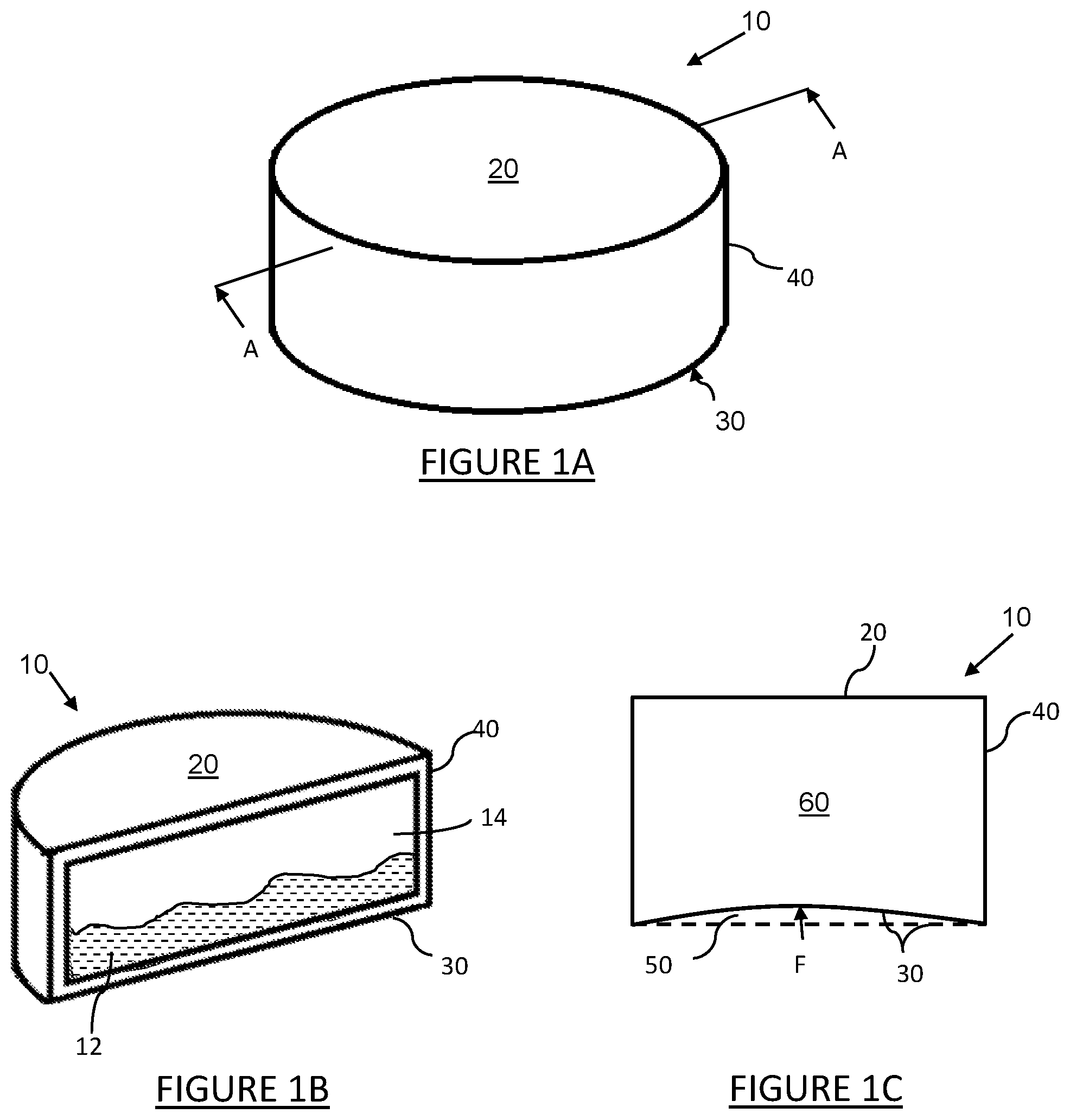
[0089] FIG. 1A shows a top perspective view of a typical can in which the presently disclosed subject matter can be used;
[0090] FIG. 1B shows a cross-sectional view of the can of FIG. 1A including contents of the can, taken along a central plane of symmetry A-A of the can;
[0091] FIG. 1C is a schematic representation of the profile of an urgable base of a can according to one embodiment of the presently disclosed subject matter in a cross-sectional view of the base taken along its central plane of symmetry, the profile being shown in a deformed state of the base in solid line and in an initial state of the base in dotted line;
[0092] FIGS. 1D and 1E show top perspective views of other typical cans in which the presently disclosed subject matter can be used;
[0093] FIG. 1F is a schematic representation of the profile of an urgable base when produced as a separate continuous solid body according to a further embodiment of the presently disclosed subject matter in a cross-sectional view taken along the central plane of symmetry, the profile being shown in a deformed state of the base in solid line and in an initial state of the base in dotted line;
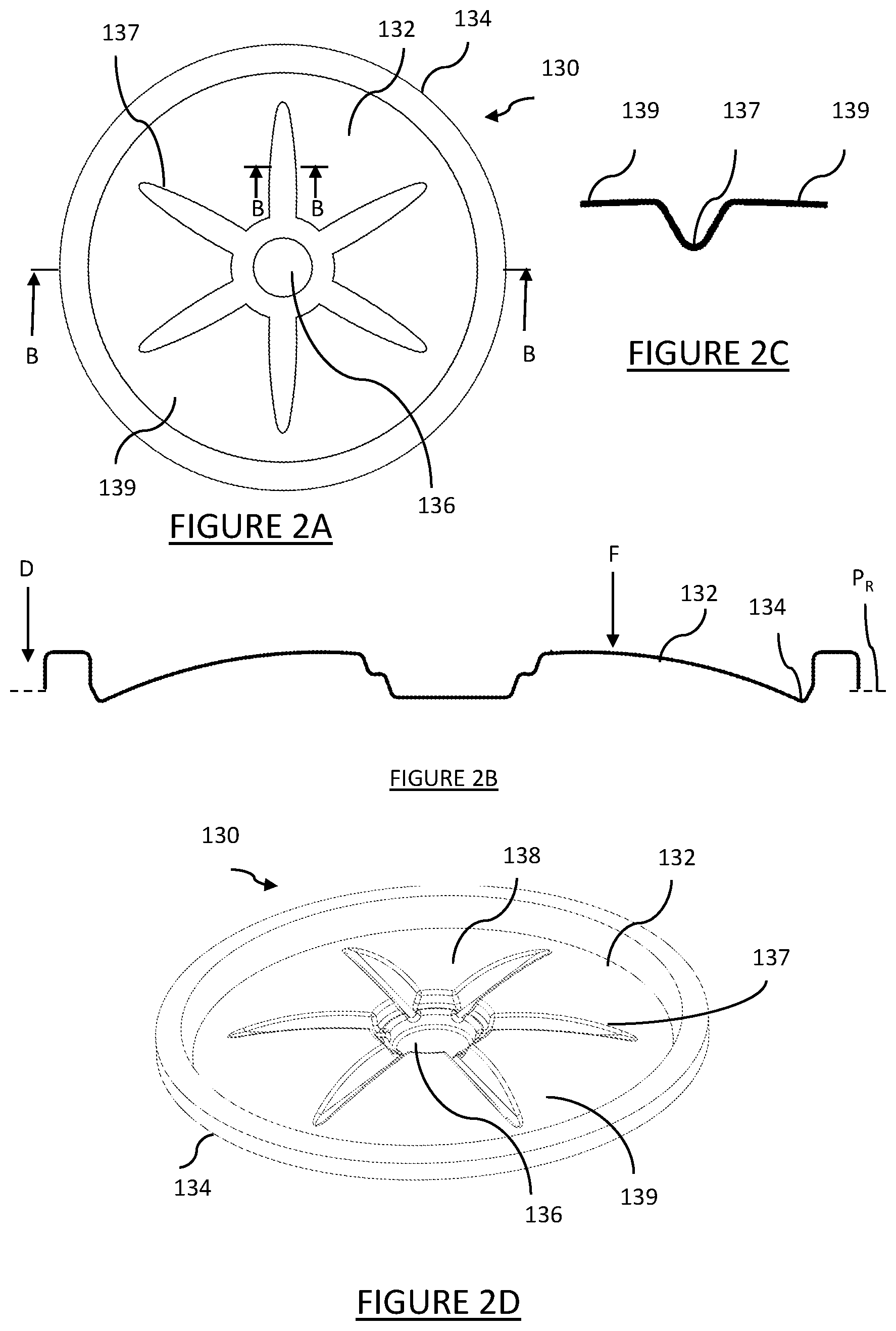
[0094] FIG. 2A shows a plan view of an urgable base according to a further embodiment of the presently disclosed subject matter, in an initial state;
[0095] FIG. 2B shows a profile of the base of FIG. 2A, in its cross-section taken along a central plane of symmetry B-B;
[0096] FIG. 2C shows a profile of the base of FIG. 2A in its partial cross-section taken along a plane C-C;
[0097] FIG. 2D shows in a top perspective view of the base of FIG. 2A;
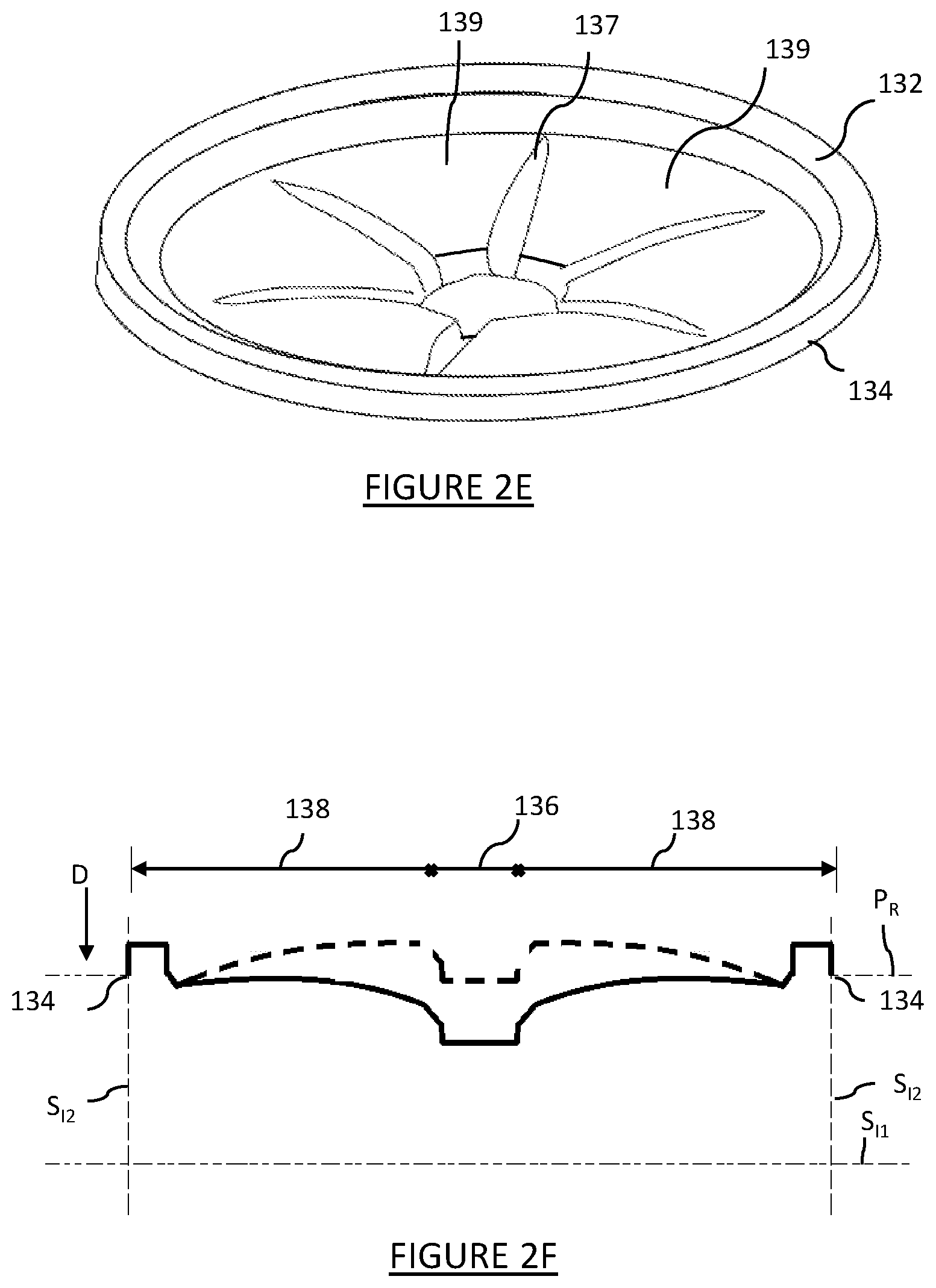
[0098] FIG. 2E shows a top perspective view of the base of FIG. 2A in a deformed state;
[0099] FIG. 2F is a schematic representation of the profile of the base of FIG. 2A in its cross-section referred to in the description of FIG. 2B, the profile being shown in a deformed state of the base in solid line and in an initial state of the base in dotted line;
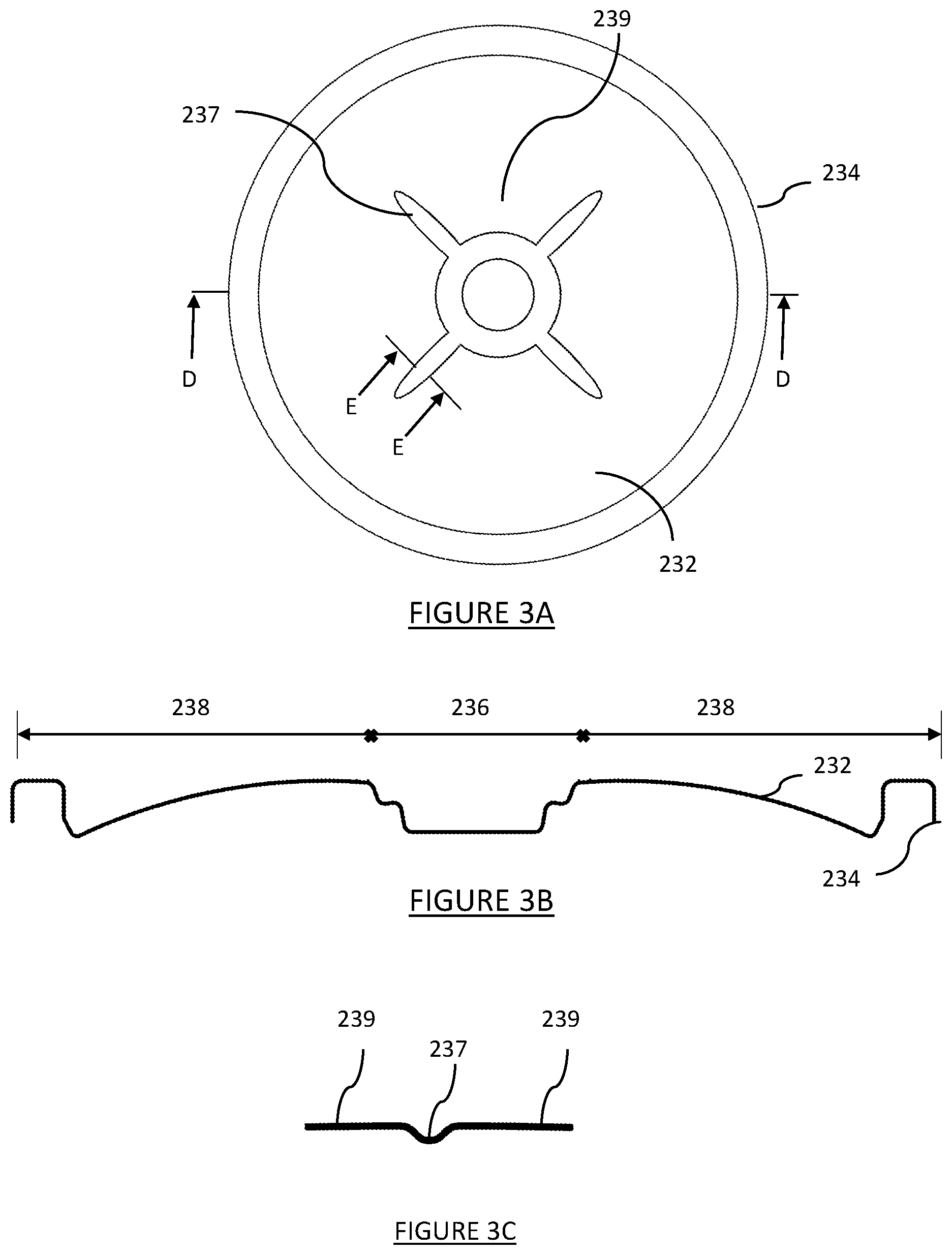
[0100] FIG. 3A shows a plan view of an urgable base according to a further embodiment of the presently disclosed subject matter, in an initial state;
[0101] FIG. 3B shows a profile of the base of FIG. 3A, in its cross-section taken along a central plane of symmetry D-D;
[0102] FIG. 3C shows a partial profile of the base of FIG. 3A, in its cross-section taken along a plane E-E;
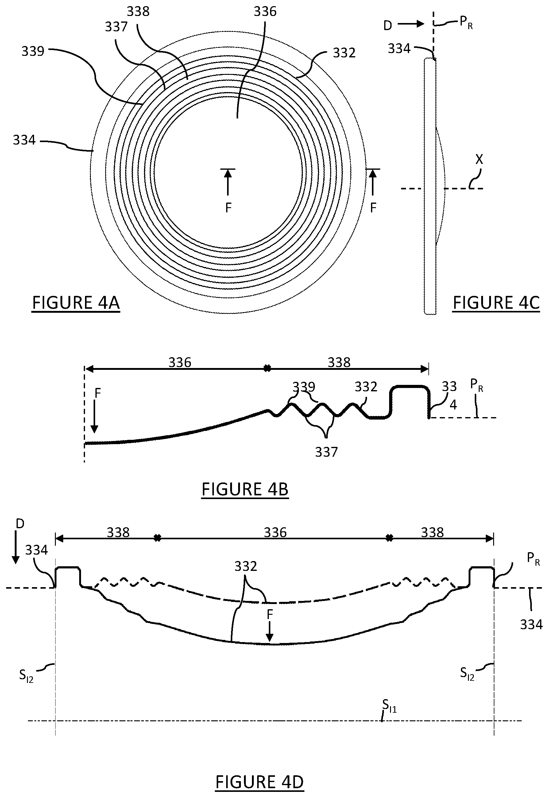
[0103] FIG. 4A shows a plan view of an urgable base according to a still further embodiment of the presently disclosed subject matter, in an initial state;
[0104] FIG. 4B shows a profile of the base of FIG. 4A, in its cross-section taken along a central plane of symmetry F-F;
[0105] FIG. 4C shows a side view of the base of FIG. 4A;
[0106] FIG. 4D is a schematic representation of the profile of the base of FIG. 4A in its profile in its cross-section referred to in the description of FIG. 4B, the profile being shown in a deformed state of the base in solid line and in an initial state of the base in dotted line;
[0107] FIG. 5A shows a top perspective view of an urgable base of a still further embodiment of the presently disclosed subject matter, in an initial state;
[0108] FIG. 5B shows a plan view of the base of FIG. 5A;
[0109] FIG. 5C shows a side view of the base of FIG. 5A;
[0110] FIG. 6 shows a top perspective view of a can having first and second opening arrangements according to a still further embodiment of the presently disclosed subject matter;
[0111] FIG. 7 shows a top perspective view of a lid for a can having first and second opening arrangements according to a still further embodiment of the presently disclosed subject matter;
[0112] FIG. 8A shows a plan view of a covering layer of a lid for a can according to a still further embodiment of the presently disclosed subject matter;
[0113] FIG. 8B shows a plan view of a strainer layer of a lid for a can;
[0114] FIG. 8C shows a top perspective view of a lid comprising the covering layer of
[0115] FIG. 8A and the strainer layer of FIG. 8B;
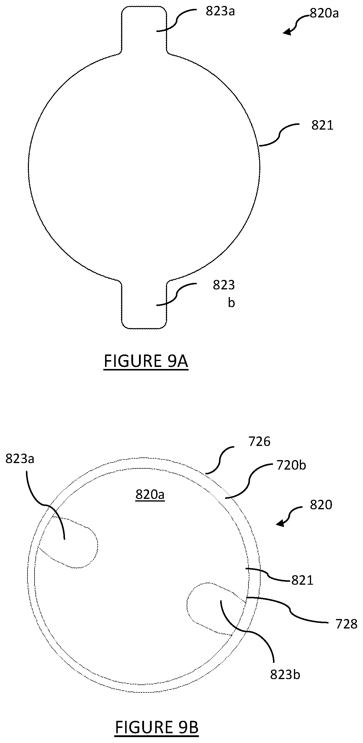
[0116] FIG. 9A shows a plan view of a covering layer of a lid for a can according to a still further embodiment of the presently disclosed subject matter;
[0117] FIG. 9B shows a plan view of a lid comprising the covering layer of FIG. 9A and a strainer layer;
[0118] FIG. 10 shows a plan view of a covering layer of a lid for a can according to a still further embodiment of the presently disclosed subject matter;
[0119] FIG. 11 shows a plan view of a ring layer of a lid for a can;
[0120] FIG. 12A shows a top perspective view of a lid for a can having first and second opening arrangements;
[0121] FIGS. 12B and 12C show a plan view of a lid for a can having first and second opening arrangements;
[0122] FIG. 13 shows a schematic top perspective view of a lid having a direction control component according to a still further embodiment of the presently disclosed subject matter;
[0123] FIG. 14A is a schematic representation of a profile of an elastic urging member, according to a further embodiment of the presently disclosed subject matter, in an initial state, in a cross-sectional view of the base member taken along its central plane of symmetry; and
[0124] FIG. 14B shows the profile of the elastic urging member of FIG. 14A, in a deformed state.
[0125] In the above list and in the description below, the term `central plane of symmetry` of an element, such as a can, its lid and/or its base, means a plane passing through the center of the element and oriented vertically when the lid or base is oriented horizontally, or when the can is oriented in an upright manner
DETAILED DESCRIPTION OF EMBODIMENTS
[0126] FIGS. 1A and 1B show a typical can 10 containing a product comprising at least one solid component and at least one liquid component. The product can be an edible or other preserved product, i.e. the can can be a can for food storage and can comprise the product. The can is shown in its ready-for-sale, hermetically sealed state with the product, and the solid and liquid components are seen in FIG. 1B, where they are designated as 12 and 14 respectively.
[0127] The can 10 in its above state comprises a lid 20, which is at least partially openable (not shown) to allow at least partial removal of the product--e.g. only the liquid 14 or the solid 12 components, or some or all of both, from the can 10. The can 10 further has a base 30 opposite the lid 20, and a side wall 40 extending between the base 30 and the lid 20.
[0128] The base 30 and the side wall 40 of the can can constitute a unitary body or the base can be fixedly connected to the side walls to form an integral body, so as to form a receptacle (not shown), to which the lid is configured to be hermetically sealingly mounted to form the can 10.
[0129] The can 10 or at least its base 30 is made of a material and is configured to undergo and withstand, without the buckling or other essential deformation, after-sealing treatments of the can required for processing canned food and known in the art, such as any one or more of pasteurization, or retorting or sterilization. These may include differential pressure, i.e. a pressure differential between the inside and outside of the can of at least 150 KPa.
[0130] The can can also be configured to withstand elevated temperatures of up to 145.degree. C. and ambient and cold storage conditions acceptable for canned food and the like.
[0131] The solid product 12 inside the can 10 can be any edible product such as meat, fish, pet food, fruit, vegetables or the like for example, and the liquid product 14 inside the can 10 may be any preserving liquid such as oil, water, brine, syrup, fruit juice or the like, for example. In a more specific example, the can may be a tuna can.
[0132] All components of the can 10, namely the lid 20, base 30 and side wall 40, or at least some of them can be made of a metallic material, or a material comprising a metallic material. For example, a laminated material may be used in the form of a plate comprising at least one of aluminum, steel or tin, optionally with one or more layers of a polymer. Alternatively, one or more of the lid 20, base 30 and side wall 40 can be made of a polymer or polymer-comprising material. Different parts of the can can be made of different materials. For example, the side wall can be made of a material different from that of the base and/or the lid, or the lid, the side wall and the base can all be made of different materials. The material from which the can or any part thereof can be made can be a metal or non-metal material comprising a polymer. Examples of metal are aluminum, tin, iron or steel coated with tin, and examples of non-metal materials are rigid synthetic materials made from organic polymers.
[0133] Although the can 10 is shown as a cylindrical container, this is not a limitation and other shapes are envisaged, for example a cuboid including with rounded corners and/or edges, an elongated cylinder or other shape as shown in FIGS. 1D and 1E.
[0134] The lid 20 can be of any conventional design. In particular, it can be openable by use of a can opener or other cutting device or comprise a scored line and a ring pull for tearing open the lid 20 along the scored line. The lid 20 can alternatively comprise a support surface arranged around at least a portion of the periphery of the side wall 40, for attachment by adhesive or other means of a peelable metallic foil or polymer film covering layer for hermetically sealing the can.
[0135] The can 10 can be manufactured in a number of ways. For example, the base 30 and/or lid 20 may be formed integrally with the side wall 40 of the can 10, for example in stamping operations, or may be formed separately and subsequently attached to the side wall 40 of the can 10 through known methods and processes such as joining with seam for example. Other processes are also suitable and would be known to the skilled person.
[0136] The above description of the typical can 10 having a ready-for-sale state in which it is hermetically sealed by the openable lid, fully applies to a can of the present example, except that the base of the present example is made of metal and has such a configuration as to be deformed at least once, when urged by a user towards the interior of the can, to reduce the contained volume of the can at least after the lid of the can has been at least partially opened. Moreover, in the present example, this metallic base, which will be hereafter referred to as an `urging member` of the can, is made of such material which is sufficiently stiff to prevent deformation thereof if it were to be free of the above configuration while having the same thickness. The term `configuration` in the context of the capability of the above urging member to be urged inwardly, means at least its configuration as seen from the exterior of the can.
[0137] FIG. 1C illustrates the above function of the urging member of the can 10 s constituted by the base 30, according to one embodiment of the presently disclosed subject matter. In FIG. 1C, the base 30 is shown to have been urged inwardly by the application thereto of an urging force F exceeding a pre-determined threshold force F.sub.Thresh, the letter being a force at which the desired deformation can yet not be obtained (see the solid line, rather than the dotted line which shows the initial state of the base 30). The force F can be applied at one or more locations of the base 30, and the pre-determined threshold F.sub.Thresh for the force F must be suitably low to allow users to easily deform the base 30, e.g. using their fingers, without the need for other devices or gadgets. FIG. 1C shows the can 10 with the base 30 in a deformed state, see the solid line of the base 30, in which the can 10 has a contained volume 60 smaller than an initial contained volume 50 in an initial state of the base 30 of the can 10 (shown in dotted lines).
[0138] Under normal, reasonable use as expected for a can, the base can be deformable in the above manner, i.e. into its final shape, or deformed state by the application of sufficient external force, only when the lid 20 has been opened, i.e. to an extent sufficient to allow at least some of the contents of the can 10, e.g. the liquid component 14, to be removed. Otherwise the can 10 would not be able to structurally withstand the much greater pasteurization and sterilization conditions required. Conversely, when the can is hermetically sealed-closed, such deformation from the initial state to the deformed state is prevented by the physical resistance to compression of the liquid and solid in the can.
[0139] In operation, a user opens the lid 20 at least partially, inverts the can 10 to allow the gravitational force to cause the product to accelerate downwards, and applies a force F greater than the threshold force F.sub.Thresh to the base 30 of the can 10. The base 30, as a result of this urging, moves from the initial state, where the can 10 has the first volume 50, to the deformed state where the can has the second, reduced volume 60.
[0140] As mentioned above, the base 30 can be produced as a separate body and then fixedly attached to the side wall of the can, or be formed as a unitary body at least with the side wall 40 of the can. FIG. 1F schematically illustrates the above operation of base 30 when produced as a separate continuous solid body 32 having a peripheral edge 34, along which the body 32 is configured to be fixedly connected to a side wall of a can, such as the side wall 40 of the can 10 described above with reference to FIGS. 1A-1E.
[0141] The body 32 has a central area 36 and an intermediate area 38 extending between the central area 36 and the peripheral edge 34. The body 32 is configured to be urged in a pre-determined urging direction D, when the peripheral edge 34 of the body 32 is fixedly held in place, by the application of a force F to the body 32 at a location of the body 32 spaced from the peripheral edge 34. In order for the body 32 to be urged, the force F applied thereto must be greater than the threshold force Fibres', i.e. F>F.sub.Thresh. The location spaced from the peripheral edge 34 may be at a center of the body 32, e.g. in the central area 36, and/or anywhere between the center and the peripheral edge 34.
[0142] The operation of the body 32, imitating its behavior when used as the base of a can, is described below with reference to FIG. 1F, where the body 32 is shown in solid line its deformed state relative to its initial state shown in dotted line. In FIG. 1F, the following imaginary planes are used for the description of the operation of the body 32:
a reference plane P.sub.R, in which the peripheral edge 34 of the body 32 lies; a first imaginary surface S.sub.I1 parallel to the reference plane P.sub.R and spaced from the reference plane P.sub.R in the urging direction D to a distance greater than that between the reference plane P.sub.R and any point of the body 32 in the deformed state, and a second imaginary surface S.sub.I2 perpendicular to the first imaginary surface S.sub.I1 and extending between the first imaginary surface Sn and the peripheral edge 34.
[0143] In the initial state of the body 32 an initial volume 50 is contained between the body 32, the first imaginary surface S.sub.I1 and the second imaginary surface S.sub.I2. In the deformed state of the body 32 a reduced volume 60 is contained between the body 32, the first imaginary surface S.sub.I1 and the second imaginary surface S.sub.I2. The reduced volume 60 is smaller than the initial volume 50.
[0144] When the body 32 as an urging member is fixedly mounted to, or unitarily formed with, a side wall of a can, such as side wall 40 of can 10 in FIGS. 1A-1E, the arrangement is such that the direction D, which is the urging direction of the base 30 is towards the inside of the can 10. As seen in FIG. 1F, in the initial state of the body 32, the intermediate area 38 extends from the peripheral edge 34 towards the central area 36 in a direction opposite to the urging direction D. Were the body 32 to be attached to a side wall of a can, this direction of extension would be towards an exterior of the can, i.e. away from the inside of the can. Conversely, in the deformed state of the body 32, as shown by the dotted line, the intermediate area 38 extends from the peripheral edge 34 towards the central area 36 generally downwards, i.e. in the same direction D as the urging direction. Were the body 32 to be attached to a side wall of a can, this direction of extension would be towards an interior of the can, i.e. towards the inside of the can.
[0145] In the described example, the body 32 can be seen to be generally convex in shape in its initial state, whereas in its deformed state, the body 32 is generally concave in shape. By concave and convex, what is meant is generally bowing in the urging direction D and generally bowing in a direction opposite to the urging direction D. In FIG. 1F these directions are below and above the reference plane P.sub.R respectively.
[0146] In this particular example, in the initial state the body 32 is substantially dome-shaped. By dome shaped, what is meant is generally resembling at least in part the upper portion of a sphere, i.e. the surface curving generally towards a central point by extending from the peripheral edge 34 towards the central area 36 in a direction opposite to the urging direction D, the gradient of the curve being increased towards the peripheral edge 34 and decreased towards the central area 36. The central area 36 of the body 32 can be stiffer than the intermediate area 38. In this case, under the application of urging force F greater than the threshold force F.sub.Thresh to the body 32, when its peripheral edge is fixed in place, the intermediate area 38 can deform preferentially to the central area 36. In this case (not shown in FIG. 1F, the central area 36 can maintain its shape in both states of the body 32, i.e. remain undeformed even in the deformed state of the body 32, whereas the intermediate area 38 changes its shape or configuration, i.e. deforms, when moving from the initial state to the deformed state of the body 32.
[0147] It should be understood that the particular shape of the initial and deformed states of the base 30 in FIGS. 1C and 1F are merely exemplary, and other possibilities are envisaged. For example, without limitation, the base 30 can have an initial convex configuration in the initial state and a less convex, planar or concave configuration in the deformed state.
[0148] Various configurations of the body 32 may be provided, which allow its use as a base of a can and to be urged under the applied force F above the threshold force F.sub.Thresh from the initial state to the deformed state. These configurations can include providing at least the intermediate area 36 of the body 32 with a shape which at least partially changes between its initial and deformed state. Non-limiting examples of such configurations are shown in FIGS. 2A-2F, 3A-3C, 4A-4D and 5A-5C.
[0149] FIGS. 2A, 2D and 2E show a body 132 configured to be used as a base 130 of a can (not shown) and having a peripheral edge 134 along which the body 132 is to be fixed to a side wall of the can, a central area 136 and an intermediate area 138. The body 132 has a first side seen in FIGS. 2A and 2D, which is the side that is to face towards the exterior of the can, when the body 132 is mounted to the side wall of the can, and a second side opposite the first side.
[0150] The body 132 as seen at its first side, is formed with a plurality of channels or grooves 137, which are spaced apart from each other in the circumferential direction of the intermediate portion. The grooves 137 extend from the central area 136 towards the peripheral edge 134, and divide the intermediate area 138 into sections 139 each having the shape of an annular sector. Although six grooves 137 and correspondingly six sections 139 are shown, any other number is envisaged. From the second side of the body 132, the grooves 137 appear to be protrusions, since the body 132 of the base has a small through-thickness, such as is the norm with sheet metal or other laminates and/or canning materials.
[0151] FIG. 2F schematically illustrates the body 132 in its deformed state (shown in solid line) and initial state (shown in dotted line), and it is seen by a comparison of the initial state in FIG. 2D and the deformed state in FIG. 2E, as well as from the profiles of FIG. 2F, that the mutual orientation of each two adjacent sections 139 disposed on either side of each groove 137 changes between the two states. In particular, it is seen in the deformed configuration shown in FIG. 2G that when the body 132 changes its state to the deformed state, the two sections 139 on either side of each groove 137 are brought closer together, i.e. an angle between them or between planes tangential thereto changes.
[0152] FIGS. 3A, 3B and 3C show an alternative arrangement of a body 232, similar in almost all respects to the body 132, and having a peripheral edge 234, a central area 236, and an intermediate area 238 extending between the central area 236 and the peripheral edge 234. The body 232 differs from the body 132 in that there are only four grooves 237 and the intermediate area 238 is divided into four section 239. The grooves 237 extend from the central area 236 towards the peripheral edge 234 but do not extend as far as the grooves 137 extend from the central area 136 to the peripheral edge 134 of the base 130. The grooves 237 however provide the same functionality as the grooves 137 described in detail above with reference to the body 132.
[0153] FIGS. 4A-4C depict a body 332 having a peripheral edge 334, a central area 336 and an intermediate area 338 extending between the central area 336 and the peripheral edge 334. The intermediate area 338 comprises a ridged formation having a plurality of concentric consecutive peaks 339 and troughs or grooves 337 configured to change their radial extension relative to a central axis X of the body 332, when an urging force F greater than the threshold force F.sub.Thresh is applied to or adjacent the central area 336. More particularly, the ridged formation of peaks 339 and troughs 337 transforms into a series of concentric concave steps.
[0154] As shown in the initial and deformed states of the body 332 the central area 336 appears to have the same shape or configuration in both states of the body, i.e. remains undeformed, whereas the intermediate area 338 changes its shape or configuration, i.e. deforms, when moving from the initial state to the deformed state. The central area 336 is recessed relative to an adjacent portion of the intermediate area 338.
[0155] FIGS. 5A-5C show a body 432 having a peripheral edge 434, a central area 436, and an intermediate area 438 extending between the central area 436 and the peripheral edge 434. The body 432 is similar to the body 332 described above in that its intermediate area 438 comprises a ridged formation having a plurality of concentric consecutive peaks 439 and troughs or grooves 437 surrounding the central area 436, which in the deformed state of the body 432 transforms into a series of concentric concave steps, i.e. steps recessed in the urging direction D.
[0156] The body 432 differs from the body 332 in that the central area 436 which is recessed in the urging direction D compared to the adjacent portion of the intermediate area 438, is flat and has an elongated shape having the shape of a rectangle with rounded shorter edges.
[0157] Although the above embodiments refer to the base of a can constituting an urging member deformable from an initial state to a deformed state such that the volume contained by the can reduces from an initial contained volume to a reduced contained volume, other possibilities for such volume reduction are envisaged. Thus, the urging member can be constituted by the side wall of a can, configured to be deformed inwards to reduce a contained volume from an initial volume to a smaller volume, i.e. smaller than the initial volume. For example, such side wall can be made of a deformable material which can include, but is not limited to, deformable metal or polymer materials. A can with such deformable side wall can comprise a conventional or a deformable base as described in any one of the above examples.
[0158] A can having a deformable urging member as described above can be provided with a conventional lid or a lid having two opening arrangements, one - allowing removal of the liquid component while preventing removal of the solid component, and the other allowing subsequent removal of the solid component, the arrangements being spaced from each other by a separating portion of the lid preventing the passage of at least the solid component through this portion at least when the first and second opening arrangements are in operation.
[0159] The opening arrangements can be configured for being manipulated during operation of the lid either by producing at least one first opening for removing the liquid component and at least one second opening for removing the solid component, or by exposing such openings to the user, in which case the openings can be pre-existing, i.e. pre-fabricated in the lid and maintained unexposed until the operation of the lid. There can also be a combination of these two options in one lid, where one opening arrangement is designed in accordance with one of the options, and the other in accordance with the other option. In any case, at least in the initial state of the lid, the spacing between the two arrangements is provided by the separating portion at least in the direction perpendicular to a central axis of the can/lid. The, or each, first opening can be essentially smaller in width and length than the at least one second opening, which can be a single opening in the second opening arrangement. In general, the second opening can occupy at least 30% of the area of the lid, optionally at least 50% of the area of the lid, whilst the or each of the first openings can occupy a much smaller area of the lid. In general, without limitation, a smallest dimension across the second opening may be, for example, at least twice the smallest dimension of the first opening, optionally at least three times, optionally at least five times or optionally at least ten times the smallest dimension of the first opening.
[0160] FIG. 6 shows a can designated as 510, which is similar to the can 10 shown in FIG. 1A and 1B, except for the design of its lid. Thus all the description provided above for the can 10, except for the description of the lid 20, is applicable to the can 510, which has a lid 520, a base 530 and a side wall 540 extending therebetween, as well as a central axis X passing through each of the lid 520 and the base 530.
[0161] The lid 520 of the can 510 has the described above first opening arrangement and second opening arrangement, represented schematically in FIG. 6 by a dotted line 550 and a dotted line 560, respectively, and the separating portion designated as 570.
[0162] The lid 520 can be formed as a unitary body at least with the side wall 540 and, optionally, with the base 530. Alternatively, it can be produced separately and attached to the side wall 540. FIG. 7 illustrates the latter option, where a lid 620 has two sides 622, 624, facing in different directions along the central axis X of the lid. The lid 620 has the described above first opening arrangement, second opening arrangement and separating portion therebetween. In FIG. 7, the first opening arrangement is represented schematically in by a dotted line 650, the second opening arrangement is represented schematically by a dotted line 660, and the separating portion therebetween is designated as 670. In this example, the first opening arrangement 650 is configured to allow transfer of the liquid component from one side of the lid 622, i.e. a first side, to the other side, or second side of the lid 624 while preventing transfer of the solid component together with the liquid component, the second opening arrangement is configured to allow transfer of the solid component from the first side 622 of the lid 620 to the second side 624 of the lid 620, and the separating portion 670 is configured to prevent the transfer of at least of the solid component at least when the first and second opening arrangements 650, 660 are in operation. The lid 620 also has a peripheral edge 626, along which the lid is configured to be mounted to the side wall 540 at an end of the side wall 540 opposite to an end associated with the base 530.
[0163] It should be indicated that the opening arrangements 550 and 560 of the lid 520 and 650 and 660 of the lid 620 shown in FIGS. 6 and 7 can include a number of components configured to be manipulated for producing first and second openings in the above lids or exposing them if pre-fabricated. Non-limiting examples of such options are presented below.
[0164] FIGS. 8A, 8B and 8C show a lid 720 which can be used in the can 510 instead of the lid 520 or 620, and which comprises two parts, namely a continuous covering layer 720a and a strainer layer 720b formed with the first and second openings mentioned above. The openings, which are pre-existing, or pre-fabricated, in the strainer layer are thus configured to be exposed for the removal of the liquid and solid components as described above, by manipulating with the covering layer 720a.
[0165] The covering layer 720a can be made of a sheet of metal foil or polymer film, or combination of any of these materials with any other materials. The strainer layer 720b can be made of the same material as the side wall 540, to which it is configured to be joined via a peripheral edge 726 of the strainer layer 720b. For example, the strainer layer can be formed of a rigid metal sheet material.
[0166] The strainer layer 720b comprises a support surface 728 proximal to the peripheral edge 726 of the lid. The support surface 728 is configured for adhering or otherwise securing an outer edge 721 of the covering layer 720a to the strainer layer 720b.
[0167] As shown, the lid 720 as a whole has two sides 722, 724, one of which, designated as 722, is an underside, or first side, of the strainer layer 720b and is configured to face toward an interior of the can when the lid 720 is mounted to the side wall of the can, and the other one, a second side, designated 724, is associated with an outer surface of the covering layer 720a. In this case, the first opening arrangement is constituted by those portions of the two layers which are configured for enabling passage of a liquid component from the first side 722 of the lid 720 to the second side 724 thereof while preventing passage of a solid component, while the second opening arrangement is constituted by those other portions of the two layers that are configured for enabling passage of a solid component from the first side 722 of the lid 720 to the second side 724 thereof. In the first and second arrangements, these portions of the strainer layer are those associated with the first and second openings mentioned above.
[0168] In general, the first and second openings in the strainer layer can have any configuration and be of any number allowing them to function as described above. In the example of FIGS. 8A to 8C, the openings in the strainer layer 720b are in the form of an elongated relatively narrow slit 725 constituting a part of the first opening arrangement, and a single large aperture 727 larger than the first aperture 725 in all its dimensions in the plan view of the lid, constituting a part of the second opening arrangement. In particular, the single large aperture 727 is wider than the elongated narrow slit 725, significantly and sufficiently so as to allow easy passage of the solid component therethrough.
[0169] In general, without limitation, a smallest dimension across the large aperture may be, for example, at least twice the width of the slit, at least three times the width of the slit, at least five times the width of the slit or at least ten times the width of the slit.
[0170] The slit 725 is for enabling passage of liquid component from the first side 722 of the lid 720 to the second side 724 thereof while preventing passage of a solid component, while the single large aperture 727 is for enabling passage of a solid component from the first side 722 of the lid 720 to the second side 724 thereof.
[0171] In the present example, the strainer layer 720b further comprises small apertures 729 which can be used instead or in addition to the slit 725 for enabling passage of a liquid component from the first side 722 of the lid 720 to the second side 724 thereof while preventing passage of a solid component. At least some of these small apertures can be used for enabling passage of a gas, such as the ambient air, from the second side 724 of the lid 720 to the first side 722 thereof. The slit 725 is spaced from the large aperture 727 and the small apertures 729 by a separating portion 770 of the lid 720 preventing the passage of the solid and liquid components through this portion 770.
[0172] In general, the covering layer 720a can be formed with any arrangement allowing at least one portion thereof to be grasped for pulling the covering layer away from the strainer layer for exposing the slit 725 and/or the small apertures 729 towards the outer-facing second side 724 of the lid and thereby operating the first opening arrangement and for subsequently exposing the large aperture 727 to the outer-facing second side 724 of the lid and thereby operating the second opening arrangement.
[0173] In the present example, the covering layer 720a comprises a pull tag 723 and this layer 720a is configured to be secured to the strainer layer 720b in such a manner that the pull tag 723 is disposed closer to the slit 725 than to the large aperture 727.
[0174] In general, the first and second openings of the first and second arrangements whether pre-fabricated or produced by the operation of these arrangements, can be disposed anywhere in the lid when seen in its plan view facing the lid's outer surface. However, the disposition of the first opening/s further from the center of the lid than that of the second opening/s and/or their spacing from one another to a maximal extent possible, allows transfer of the liquid component through the first openings with less chance of accidental transfer of liquid and/or solid from the second openings at the same time. Further, there is less likelihood that transfer of the liquid component via the first openings will soil any part of the second opening arrangement and/or the fingers of a user.
[0175] In the present example, the slit 725 and the large aperture 727 of the strainer layer 720b are positioned spaced from one another to a maximal extent, i.e. circumferentially spaced to a maximal distance from one another, and the pull tag 723 of the covering layer 720a is arranged to be positioned by the slit 725 and diametrically opposed from the large aperture 727, when the covering layer 720a is secured to the strainer layer 720b.
[0176] In operation, a user can pull the pull tag 723 to detach a first portion of the lid 720, namely a first part of the covering layer 720a from the remainder of the lid 720, i.e. from strainer layer 720b and thereby expose the pre-existing, or pre-fabricated slit 725 and possibly some or all of the pre-existing, or pre-fabricated small apertures 729. Such detachment can involve peeling of adhesive or tearing of the outer edge 721 of the covering layer 720a. In this case, at least in the initial state of the lid 720, the first part of the covering layer 720a together with at least the slit 725 and, optionally, the small apertures 729, can be considered to be a first opening arrangement.
[0177] With the first part of the covering layer 720a detached, a can having as its lid the lid 720 can be tipped to allow the liquid component inside the can to pass from the first side 722 to the second side 724 of the lid 720, such as under the force of gravity. Since the slit 725 has an arc-shaped relatively narrow elongated shape, the liquid component will flow out of its central area, and the ends of the slit can allow air to flow in the opposite direction if desired, in order to ensure equal pressure inside and outside the can if the contained volume of the can is not reduced as the liquid flows out. Alternatively or additionally, if the small apertures 729 are exposed by further detachment of the covering layer 720a, the liquid component can flow out of at least some/one of them, and/or air can flow in the opposite direction via at least the other/s if desired, in order to ensure equal pressure inside and outside the can if the contained volume of the can is not reduced as the liquid flows out.
[0178] Once the liquid component has been removed, a user can continue to pull the pull tag 723 to detach a second portion of the lid 720, namely a second part of the covering layer 720a from the remainder of the lid 720, i.e. from strainer layer 720b and thereby expose the pre-existing, or pre-fabricated large aperture 727. Such detachment can involve peeling of adhesive or tearing of the outer edge 721 of the covering layer 720a. In some cases, such detachment can result in removing the covering layer 720a entirely from the strainer layer 720b, while in other cases, at least a portion of the covering layer 720a can remain attached to the strainer layer 720b. At least in the initial state of the lid 710, the second part of the covering layer 720a together with the large aperture 727 can be considered to be a second opening arrangement spaced from the first opening arrangement at least by the separating portion 770. With the large aperture 727 exposed, the solid component can be removed from the can, i.e. transferred or passed from the first side 722 of the lid 720 to the second side 724 of the lid 720.
[0179] In the above arrangement only the single pull tab 723 is required to expose, in sequence with the extent of detaching of the lid 720, the first aperture 725 with the small optional apertures 729, followed by the second aperture 727.
[0180] FIGS. 9A and 9B show a lid 820, which is similar to the lid 720 described above and which differs therefrom only in that its covering layer 820a has two pull tags, namely a first pull tag 823a and a second pull tag 823b, instead of the single pull tag 723.
[0181] In general, when such two pull tags are used, they can have any disposition corresponding to the disposition of the respective first and second openings, as long as they are spaced along the outer edge 821 of the covering layer 820a. In the present example, the first and second pull tags 823a, 823b are disposed diametrically opposed from one another, with the first pull tag 823a being closer to the slit 725 than to the large aperture 727, and the second pull tag 823b is closer to the large 727 than to the slit 725.
[0182] The operation of the lid 820 is the same as described above for the lid 720 except that use can first be made of the first pull tag 823a to detach a first portion of the lid 820 from the strainer layer 720b and thereby expose the slit 725 and possibly some of the small apertures 729 to the exterior of the lid at its outer side 724, and then of the second pull tag 823b to detach a second portion of the lid 820 from strainer layer 720b and thereby expose the large aperture 727 to the exterior of the lid at its outer side 724.
[0183] Since in the present example, there are two pull tags 823a, 823b which are spaced apart from one another, in this case being diametrically opposed, the second pull tag 823b will not accidentally become soiled by the liquid component when the can is tipped to remove the liquid component, even if the first pull tag 823a is accidentally soiled. In this way, a user can avoid getting their hands dirty in the process of draining the liquid component from the can and subsequently removing the solid component.
[0184] In general, another option is to provide a covering layer having at least one pull tag arranged to be capable of completely tearing off an associated portion of the covering the layer to expose at least one first pre-existing, or pre-fabricated aperture. Optionally, the torn off portion of the covering layer is less than a third of the area of the covering layer excluding the pull tags.
[0185] FIG. 10 shows one example of such option in which a covering layer 920a is similar to the covering layer 820a described above and differs therefrom only in that in the covering layer 920a, the first pull tag 923a protrudes from an outer edge 921 of the covering layer 920a in a substantially tangential direction, i.e. transversely to a radially outward direction of the covering layer 920a. With this arrangement, an acute angle a is formed between the first pull tag 923a and the adjacent portion of the outer edge 921 of the covering layer 920a, due to which pulling of the first pull tag 923a applies a high stress at the vertex of angle a, causing a portion of the covering layer 920a to tear off, e.g. approximately along the dashed line 925 shown in FIG. 10. Of course, this is possible when the covering layer is made of an easily torn material such as aluminum foil of a suitable thickness. The foil can further be provided with a configuration facilitating its tearing off such as e.g. grooves, semi-perforated lines, etc., which can be configured to provide one or more tears along lines other than the schematic line 925 shown in FIG. 10. The second pull tag 923b can be used subsequently to expose the second pre-existing, or pre-fabricated aperture.
[0186] One alternative design of a two-layer lid of the kind described above, which comprises a strainer layer with different pre-fabricated openings and a covering layer covering all of them, can be in that the covering layer is not a continuous layer extending along the entire area of the strainer layer but rather a number of individual layer portions each covering its own opening or a group of openings.
[0187] In another alternative design of a two-layer lid, instead of the strainer layer, the lid can have an inner layer in the form of a frame having a single large opening, a peripheral edge along which the lid is to merge with or be mounted to a side wall of a can, and a support surface extending therebetween for supporting the covering layer. In this case, the covering layer can be configured to be selectively detached from the support surface so as to expose, at the second side of the lid, different portions of the single pre-existing, or pre-fabricated opening spaced apart from each other by an area of the covering layer extending therebetween.
[0188] A still further alternative design of a lid according to the presently disclosed subject matter can be in that the lid has a first area with at least one first pre-fabricated opening covered by its individual covering layer, and a second area, in which at least one second opening can be produced by the detachment of at least a portion of the second area from the lid.
[0189] Some examples of the above alternative designs are described below.
[0190] FIG. 11 shows a frame layer having the form of a ring 1020b comprising a peripheral edge 1026 for joining to a side wall of a can, a single large aperture 1025 occupying a majority of the area of the ring layer 1020b, and a support surface 1028 extending therebetween. With the ring layer 1020b, a lid can be formed by adhering or otherwise joining one of the covering layers 820a and 920a at its respective outer edge 821, 921 to the support surface 1028.
[0191] In order to operate the lid to allow drainage of liquid when the peripheral edge 1026 of the ring layer 1020b is joined to a side wall of a can comprising a liquid component and a solid component, one of the pull tags 823a, 823b or 923a of the respective covering layer 820a, 920a is pulled to detach or tear respectively a first portion of the respective lid, i.e. a first part of the respective covering layer at its respective outer edge 821, 921 from the support surface 1028 of the ring layer 1020b. The covering layer should be attached to the support surface 1028 so as to allow only a slight detachment of the covering layer 820a, or slight removal of the portion of the covering layer 920a, from the support surface so as to expose a portion of the aperture 1025 small enough to prevent passage of the solid component in the can but large enough to allow liquid to flow out of the can when tipped. The pull tag 823a, 823b or 923a together with the slightly detachable or removable portion of the covering layer 820a, 920a, and optionally with the respective, slightly exposable, portion of the aperture, can be considered to be a first opening arrangement.
[0192] In order to subsequently remove the solid component from the can, the other of the pull tags which were not previously pulled to detach the covering layer may be pulled to detach the respective covering layer at least along a majority of its outer edge to expose at least a majority of the pre-existing, or pre-fabricated aperture 1025. The solid component can then be removed from the exposed aperture. The exposed at least majority of the aperture, together with the other of the pull tags 823a, 823b or 923b, and the detached portion of the respective covering layer can be considered to be a second opening arrangement.
[0193] With reference to FIG. 12A, there is shown a lid 1120 comprising a central portion 1120a and a circumferential portion 1120b with a peripheral edge 1126 along which the lid is configured to be mounted, joined or otherwise attached to a side wall. The lid 1120 has two sides 1122, 1124, an inner side or first side 1122 configured to face toward an interior of a can and an outer side or second side 1224 configured to face towards an exterior of a can, when the lid is mounted to a side wall of a can.
[0194] The lid 1120 has a first opening arrangement comprising a tab 1123a, peelable from the remainder of the lid at its second side 1224, to expose a pre-existing, or pre-fabricated small first aperture pre-formed in the central portion 1120a. The peelable tab 1123a can be formed of metal or polymer for example, and may be adhered or otherwise joined to hermetically seal the first aperture. In operation of the first opening arrangement by at least partially removing the peelable tab 1123a to expose at least a part of the first aperture, the first opening arrangement allows transfer of the liquid component from the first side of the lid 1122 to the second side of the lid 1124 while preventing removal of the solid component together with the liquid component.
[0195] The lid 1120 also has a second opening arrangement comprising, in the initial state of the lid, a ring pull 1123b attached to the central portion 1120a, and a scored or semi-perforated groove 1127 surrounding at least a majority of the central portion 1120a, between the central portion 1120a and the circumferential portion 1120b. In operation of the second opening arrangement, the ring pull 1123b is operated to tear the lid 1120 along at least a majority of the groove 1127, such that at least a majority of the central portion 1120a of the lid 1120 is separated and detached from the remainder of the lid, i.e. from the circumferential portion thereof, to provide a single large aperture occupying a majority of the area of the lid 1120. The exposure of the single large aperture, i.e. the second aperture, is configured to allow removal of the solid component from the first side 1122 of the lid 1120 to the second side 1124 of the lid 1120. In the initial state of the lid 1120, the second opening arrangement is spaced from the first opening arrangement by a portion 1170 of the lid 1120 preventing the passage of the solid component and the liquid component through this portion 1170.
[0196] FIGS. 12B and 12C show an alternative arrangement for a lid 1220. Lid 1220 comprises a central portion 1220a and a circumferential portion 1220b. The circumferential portion 1220b comprises a peripheral edge 1226 along which the lid is configured to be mounted, joined or otherwise attached to a side wall of a can at an end of the side wall opposite to that at which a base is configured to be connected to the side wall. The lid 1220 has two sides one of which is configured to face toward an interior of the can when the lid is mounted to the side wall of the can.
[0197] In general, a lid may comprise two separate scored or semi-perforated grooves surrounding at least a part of the central portion of the lid, each arranged to be opened by a separate opening arrangement such as ring pulls. One groove may be shorter than the other, so as to provide a smaller opening once torn or cut along. Alternatively, there may be a single groove, openable by tearing or cutting in two spaced-apart locations by two separate opening mechanisms, such as two separate ring pulls.
[0198] In this example, the lid 1220 has a first opening arrangement comprising a first ring pull 1223a arranged at a first location next to a scored or semi-perforated single groove 1225 surrounding the central portion 1220a of the lid 1220. The lid 1220 also has a second opening arrangement comprising a second ring pull 1223b arranged next to the scored or semi-perforated single groove 1225, at a second location spaced from the first location. In the initial state of the lid, the second opening arrangement is spaced from the first opening arrangement by a portion 1270 of the central portion 1220a of the lid 1220 preventing the passage of the solid and liquid components through this portion 1270. The spacing is in a plane perpendicular to the central axis X. Each of the opening arrangements, i.e. ring pulls 1223a, 1223b is associated with its own portion of the groove 1225.
[0199] In operation of the first opening arrangement, the first ring pull 1223a is operated to tear the lid 1220, i.e. to tear and detach the central portion 1220a of the lid 1220 from the remainder of the lid, i.e. from the circumferential portion 1220b along a part of the groove 1225 associated with the first ring pull 1223a, to provide a first aperture small enough to prevent passage of the solid component in the can but large enough to allow liquid component to flow out of the can when tipped. The provided first aperture can be considered to be a part of the first opening arrangement, i.e. together with the first ring pull 1223a.
[0200] In operation of the second opening arrangement, the second ring pull 1223b is operated to tear the lid 1220, i.e. to tear and detach the central portion 1220a of the lid 1220 from the remainder of the lid, i.e. from the circumferential portion 1220b along at least a majority of the part of the groove 1225 associated with the second ring pull 1223b, to provide a second aperture large enough to allow passage of the solid component from the can, i.e. to allow removal of the solid component from the first side of the lid 1220 to the second side of the lid 1220. The provided second aperture can be considered to be a part of the second opening arrangement, i.e. together with the second ring pull 1223b.
[0201] In some arrangements, the lid is configured so that the portion of the lid which is detachable during operation of the first opening arrangement is smaller than the portion of the lid which is detachable during operation of the second opening arrangement.
[0202] In at least some of the above embodiments, the first opening arrangement may allow passage of air therethrough while in operation and when liquid is being removed, if desired.
[0203] In any of the above arrangements, there may be provided, adhered or otherwise joined to at least a portion of the lid proximate to the first opening arrangement, a direction control component, such as an elongate tongue arranged to provide a flow-path for liquid being removed from the can. This elongate tongue can control and direct the flow of the liquid component, so as to avoid accidental soiling of other portions of the lid by the liquid component. Subsequent to use, the elongate tongue may be detachable from the lid, such as by tearing or peeling off, prior or subsequent to operating the second opening arrangement. FIG. 13 illustrates one example of a lid 1320 having two ring-pulls 1323a, 1323b. Attached to one of the ring pulls 1323a is an elongate tongue 1327.
[0204] In any of the above arrangements, the deformation of the urging member from the initial state to the deformed state can be plastic deformation. In such cases, by applying urging force which exceeds a pre-determined threshold, the state of the urging member is changed from the initial state thereof to the deformed state thereof and is maintained in this state after the urging force is released, i.e. no longer applied. Alternatively, the deformation of the urging member from the initial state to the deformed state can be elastic deformation. In such cases, after the urging member is deformed to the deformed state by the urging force applied thereto by the user, and the urging force is released, the urging member can urge back into its initial state. Moreover, the urging member can be configured to be repeatedly elastically deformed in this manner, while returning each time to its initial state or to a state closer to the initial state than to the deformed state.
[0205] In general, can be configured so as to have elastic properties suitable for it to operate in the above elastic manner under the repeated application and release of the urging force F.
[0206] In this case, the urging member should be configured so that the urging force F, under which the urging member can have properties suitable for its above elastic operation, will meet the following condition F.sub.plastic>F>F.sub.Thresh, in which F.sub.plastic is a pre-determined threshold at which the material would undergo plastic deformation preventing its return into the initial position or close thereto; and F.sub.Thresh is, as described above, an urging force at which the urging member cannot yet be deformed to a desired extent.
[0207] To be able to repeatedly undergo the above elastic deformation, the urging member can have corresponding elastic properties and, in its cross-sectional view, a convex shape in the initial state, whilst being less convex or planar or concave in the elastically deformed state.
[0208] When constituting a base in a can in a ready-for-sale state, being hermetically sealed by an openable lid, the urging member can be configured to be operated in the above elastic manner at least when the lid is at least partially opened.
[0209] In operation of such elastic urging member in a can of any of the above examples, after a portion of the lid was opened (as aforementioned) and after the user ceases to apply urging force on the elastic urging member, the elastic properties thereof will urge the elastic urging member back into its initial state, due to which the contained volume of the can will increase relative to its volume with the urging member in its deformed state.
[0210] The urging member can be in the form of a thin plate made of metal such as steel, aluminum, tin and the like, having a convex shape and such dimensions as to be capable to be repeatedly elastically bent upon the application of the urging force at its central area, and to return back each time when the force is released.
[0211] When such metal plate constitutes a base of a can containing a product having a liquid and a solid component, after having a lid with a portion thereof being suitably opened, by repeatedly urging the plate, more and more of the liquid component can be pumped out from the can through the opened portion of the lid, and be replaced by air sucked into the can when the plate returns back from its deformed state, rendering the operation of the plate to be similar to that of a membrane in a dozing pump. Such operation can result in the liquid component being gradually and controllably removed from the can.
[0212] When the product is a consumer food product, the metal plate can be configured to be elastically bent at an urging force F which can be routinely applied to the base by a finger/s of an average consumer to easily deform the base as desired. For example, such force can be about 20N (or 2 Kg of force).
[0213] The above metal plate can have any desired configuration in a plan view thereof, conforming to that of a can where the urging member is to be used as a base, e.g. it can have such regular shape as round, oval, square or rectangular.
[0214] The metal plate can be in the form of a tin-coated or chrome-coated steel plate with a temper in the range from TS275 to TH620 according to European standard EN 10202:2001, or of similar temper according to other corresponding standards, and having a thickness in the range from 0.16 mm to 0.21 mm.
[0215] The metal plate can have a ratio between its thickness and maximal dimension in the plan view in the range of 0.001-0.005, more particularly, between 0.002 and 0.003. Such plate can have a maximal deformation distance between the locations of its center point in the initial and maximally elastically bent state in the range of 5 to 10 mm and more particularly in the range of 6-8 mm.
[0216] One specific example of a can having a base in the form of a metal plate is a round tuna can having a base of a standard thickness of 0.16 mm and diameter of 80 mm. The base of the can can be made of tin-coated steel plate of one of the above types and having a convex shape in the initial state and elastically bendable inwardly into a substantially planar (or at least more planar than convex) shape upon the application of an urging force of about 20N at its central area. Its convexity in the initial state can be such that the maximal deformation distance between the two states can be about 7 mm.
[0217] FIGS. 14A and 14B illustrate one example of a metal constituting a base 1430 of a can 1400, and having a peripheral edge 1434 at which the base 1430 is connected to a side wall 1410 of the can 1400, a central area 1436 and an intermediate area 1438 therebetween.
[0218] It should be understood that the particular shape of the base 1430 in its initial and deformed states shown in FIGS. 14A and 14B are merely exemplary, and other possibilities are envisaged. For example, without limitation, the base 1430 can have an initial convex or planar configuration in the initial state and, respectively, a less convex or planar, or concave configuration in the deformed state.
[0219] FIG. 14A schematically illustrates a metal can 1400 for a food product, such as e.g. a tuna can, with the base 1430 connected to the side wall 1410 of the can adjacent its peripheral edge 1434. The metal can 1400 having a lid 1440, the lid 1440 being slightly opened, in any conventional manner or any manner described in the previous examples, to provide an opened portion 1441. The opened portion 1441 is configured with a size sufficient for a liquid component of the product (e.g. oil), but insufficient for a solid component of the product (e.g. tuna chunks), to pass therethrough. As seen, the can 1400 is held in a turned-on position with its base 1430 facing upwardly and its lid 1440 facing downwardly.
[0220] The base 1430 has a convex shape in its initial state (shown in solid line in FIG. 14A). As seen in FIG. 14A, in the present example in spite of being convex, the base does not protrude outwardly from the peripheral edge of the can, to allow conventional packaging thereof.
[0221] The can 1400 is shown in FIG. 14A with an urging force F applied to its central area 1436 for bending the base 1430 inwardly from its initial, convex shape towards its deformed, planar state (shown in dashed line in FIG. 14A). In order to prevent plastic deformation of the body, the urging force F applied on the base 1430 should be lower than F.sub.plastic of the base 1430. During the elastic deformation, the contained volume of the can 1400 will decrease relative to its volume with the urging member in its initial state, and as such liquid component is forced out of the can 1400 through the opened portion 1441 in the lid 1440 in the direction of arrow O.
[0222] FIG. 14B schematically illustrates the can 1400 of FIG. 14A with the base 1430 in its deformed state (shown in solid line), when the urging force F has been released, and a return-back force F developed in the base 1430 in a direction D' opposite to the direction D, due to strains and stresses created therein when it was bent inwardly, causing the base to return back towards the initial state thereof (shown in dashed line in FIG. 14B). At this time, the contained volume of the can will increase relative to its volume with the urging member in its deformed state, and air will be forced into the can 1400 through an opened portion 1441 in the lid 1440 in the direction of arrow I.
[0223] Repeatedly urging the base 1430 inwardly by applying the force F and releasing this force to allow the base 1430 to be deformed and return back to its non-deformed state or to a state close to its non-deformed state, will cause more and more of the liquid component to be removed from the can 1400 out of the opened portion 1441 of the lid 1440, and will be replaced by air sucked into the can 1400 by the returned movement of the base 1430. Once no more liquid component is forced out of the opened portion 1441 of the lid 1440, the can 1400 can be turned over and the lid 1440 can be further opened to remove the solid component.
* * * * *
D00000
D00001
D00002
D00003
D00004
D00005
D00006
D00007
D00008
D00009
D00010
D00011
D00012
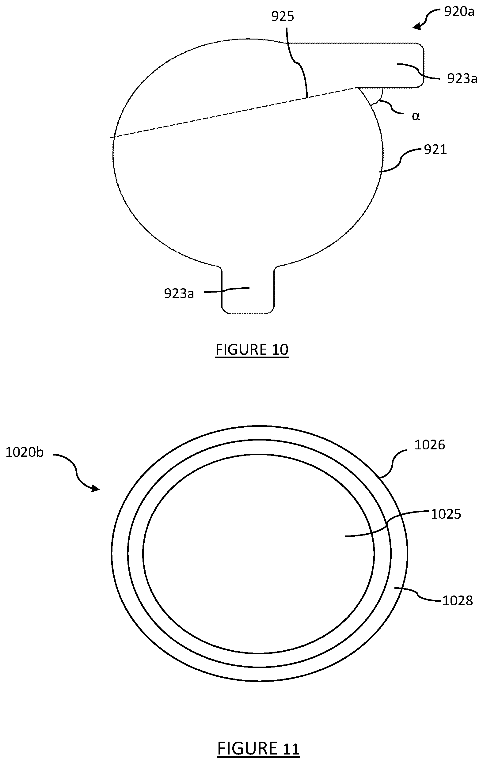
D00013
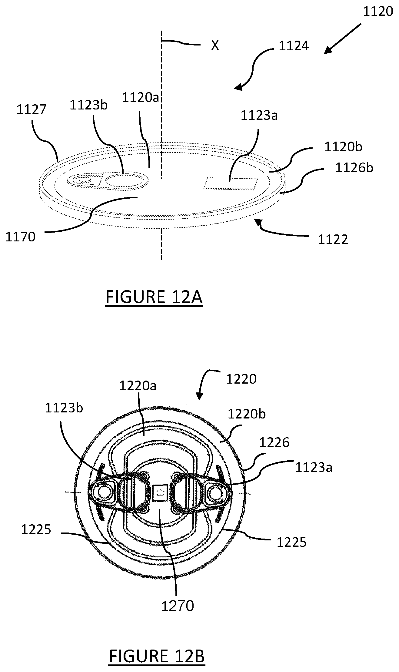
D00014

D00015
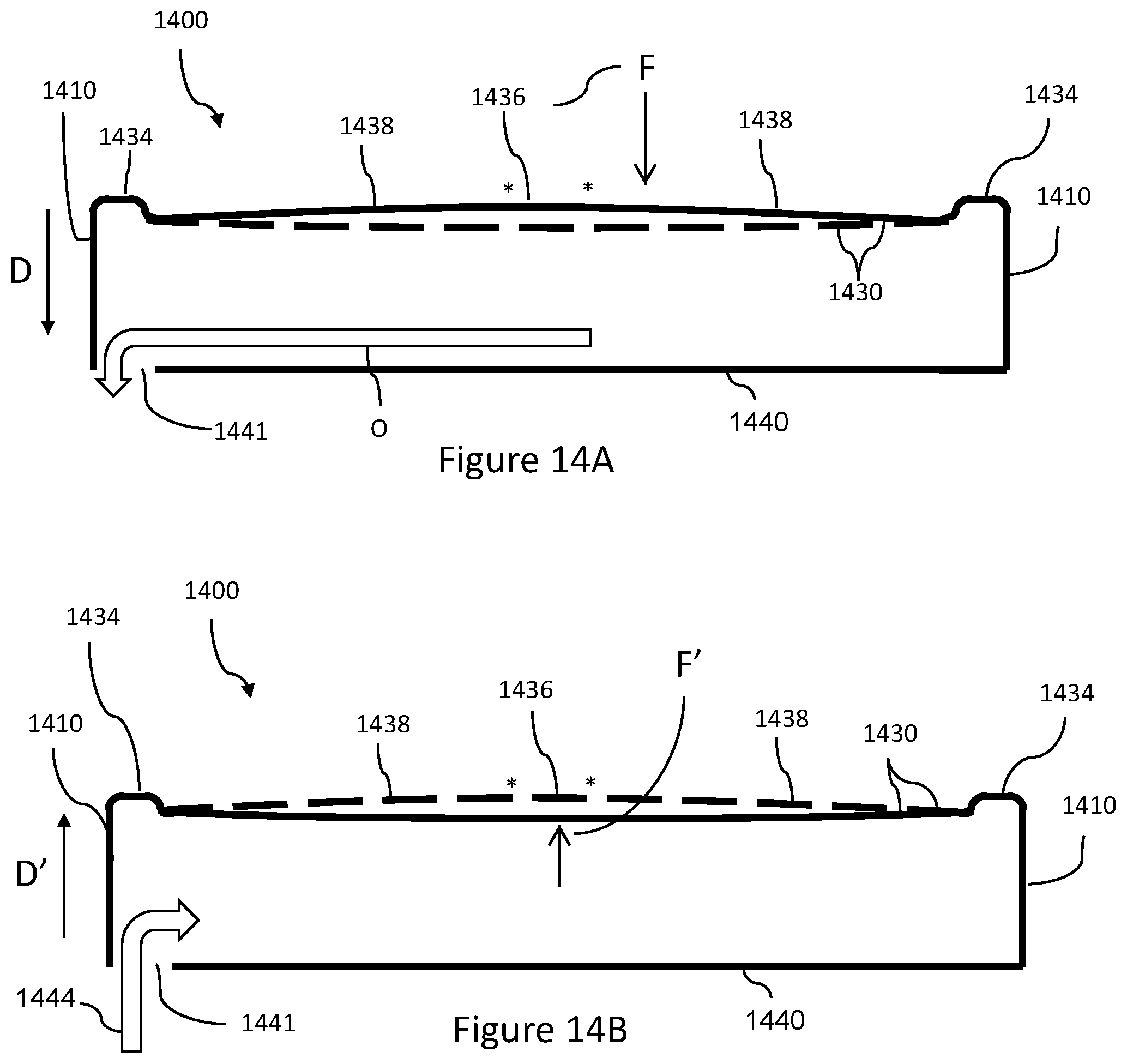
XML
uspto.report is an independent third-party trademark research tool that is not affiliated, endorsed, or sponsored by the United States Patent and Trademark Office (USPTO) or any other governmental organization. The information provided by uspto.report is based on publicly available data at the time of writing and is intended for informational purposes only.
While we strive to provide accurate and up-to-date information, we do not guarantee the accuracy, completeness, reliability, or suitability of the information displayed on this site. The use of this site is at your own risk. Any reliance you place on such information is therefore strictly at your own risk.
All official trademark data, including owner information, should be verified by visiting the official USPTO website at www.uspto.gov. This site is not intended to replace professional legal advice and should not be used as a substitute for consulting with a legal professional who is knowledgeable about trademark law.