Automatic Packaging Machine Including Circulation System
JEON; Byung Sun ; et al.
U.S. patent application number 16/262501 was filed with the patent office on 2020-07-02 for automatic packaging machine including circulation system. The applicant listed for this patent is Byung Sun JEON JEON. Invention is credited to Byung Jin JEON, Byung Sun JEON.
| Application Number | 20200207492 16/262501 |
| Document ID | / |
| Family ID | 66678351 |
| Filed Date | 2020-07-02 |


| United States Patent Application | 20200207492 |
| Kind Code | A1 |
| JEON; Byung Sun ; et al. | July 2, 2020 |
AUTOMATIC PACKAGING MACHINE INCLUDING CIRCULATION SYSTEM
Abstract
An automatic packaging system for continuously and automatically packaging products without interruption using triple circulation systems. The triple circulation systems include an unpackaged product feeding circulation system continuously feeding unpackaged products via circulation, a package feeding circulation system continuously feeding packages via circulation, and a packaged product circulation conveying system continuously transporting packaged products wrapped in the packages via circulation. The automatic packaging system continuously and automatically packages products without interruption, thereby efficiently improving productivity.
| Inventors: | JEON; Byung Sun; (Gimpo-si, KR) ; JEON; Byung Jin; (Uijeongbu-si, KR) | ||||||||||
| Applicant: |
|
||||||||||
|---|---|---|---|---|---|---|---|---|---|---|---|
| Family ID: | 66678351 | ||||||||||
| Appl. No.: | 16/262501 | ||||||||||
| Filed: | January 30, 2019 |
| Current U.S. Class: | 1/1 |
| Current CPC Class: | B65B 35/24 20130101; B65B 57/00 20130101; B65B 25/064 20130101; B65B 43/30 20130101; B65B 5/045 20130101 |
| International Class: | B65B 5/04 20060101 B65B005/04; B65B 25/06 20060101 B65B025/06; B65B 35/24 20060101 B65B035/24; B65B 43/30 20060101 B65B043/30; B65B 57/00 20060101 B65B057/00 |
Foreign Application Data
| Date | Code | Application Number |
|---|---|---|
| Jan 2, 2019 | KR | 10-2019-0000338 |
Claims
1. An automatic packaging machine comprising: an unpackaged product feeding circulation system comprising an unpackaged product transport conveyor disposed in a space defined by a base frame and unpackaged product transport containers disposed on the unpackaged product transport conveyor at equal distances from each other so as to circulate on the unpackaged product transport conveyor; a package feeding circulation system comprising a package feeding conveyor disposed on one side of the unpackaged product feeding circulation system and package loading plates disposed on the package feeding conveyor at equal distances from each other so as to circulate on the package feeding conveyor, such that packages are loaded on the package loading plates; a cylinder-type unpackaged product inserting unit disposed above the unpackaged product feeding circulation system to insert unpackaged products transported by the unpackaged product transport conveyor into the packages; a package opening unit disposed above the package feeding circulation system to be movable back and forth, and comprising an upper guide and a side guide, with a pair of blades being provided on the upper guide to open a mouth of each of the packages by a grippers-like opening action, thereby allowing the unpackaged product inserting unit to insert an unpackaged product into each of the packages; and a packaged product circulation conveying system comprising a packaged product transport conveyor disposed on one side of the package feeding circulation system, a packaged product support plate disposed on the packaged product transport conveyor at equal distances from each other as to circulate on the packaged product transport conveyor, an upper holder pivotably provided above the packaged product support plate to hold each of the packages in which the product is inserted, a coil spring downwardly pivoting the upper holder by elastic force, and an upper holder controller disposed on a product transfer line, in a position above the upper holder, to be movable up and down, thereby upwardly pivoting the upper holder.
2. The automatic packaging machine according to claim 1, wherein each of the unpackaged product transport containers has a V-shaped, rounded, or polygonal side-view geometry, with an upper portion being open.
3. The automatic packaging machine according to claim 1, wherein the unpackaged product inserting unit comprises a pair of servo cylinders, a pair of pneumatic cylinders, or a combination of a servo cylinder and a pneumatic cylinder.
4. The automatic packaging machine according to claim 1, further comprising a lift disposed on the side guide, such that an upper portion thereof is pivotable, to raise a lower portion of each of the packages.
5. The automatic packaging machine according to claim 1, further comprising a pneumatic unit configured to widen the mouth of each of the packages by blowing air toward the mouth using a valve connected to an air intake unit disposed in a lower space defined by the base frame and an air discharging unit connected to the valve.
6. The automatic packaging machine according to claim 5, further comprising a product tight fitting unit disposed on a package transfer line to tightly fit the packages to packaged products, wherein the product tight fitting unit comprises: a package entrance guide configured to guide entrance of the packages in which the packaged products are inserted; grippers pivoting to grip the mouth of each of the packages; and a reciprocation unit moving the grippers back and forth.
7. The automatic packaging machine according to claim 6, further comprising a loading unit comprising a loading chamber defined by the base frame, wherein, in a position in which the package is fitted to the packaged product by the product tight fitting unit, when the mouth of each of the packages is bound and then remainders are cut from the mouth of each of the packages, the loading unit accommodates the remainders via vacuum suction.
8. The automatic packaging machine according to claim 7, wherein the loading chamber comprises two or more loading chambers, such that, when the remainders are accumulated in one of the loading chambers to be detected by a sensor, a three-way valve connected to the loading chambers is controlled to automatically replace the one loading chamber with the other loading chamber.
Description
CROSS REFERENCE TO RELATED APPLICATION
[0001] The present application claims priority to Korean Patent Application Number 10-2019-0000338 filed on Jan. 2, 2019, the entire contents of which are incorporated herein for all purposes by this reference.
BACKGROUND
Field
[0002] The present disclosure relates to an automatic packaging system and, more particularly, to an automatic packaging system for continuously packaging products, such as poultry, individually or in blocks.
Description
[0003] For example, types of poultry commonly used for foods include chicken, duck, quail, and the like. Such edible poultry may have a variety of shapes depending on the packaging method thereof.
[0004] In general, large amounts of workers, space, and time are consumed in packaging such poultry, since individual poultry is manually packaged.
[0005] That is, in the related art, when individual poultry is packaged, a large amount of workers are used to manually package individual poultry, due to absence of an automatic packaging machine. For the packaging operation, not only workers, but also a working space and a large amount of packaging time, are required.
[0006] In addition, the related-art method of manually packaging individual poultry is exposed to a high risk of cross-contamination.
[0007] Accordingly, efforts have been undertaken intensively in a variety of aspects in fields to solve problems caused by such a labor-intensive structure. However, no clear solutions have been proposed to date.
[0008] The information disclosed in the Background section is only provided for a better understanding of the background and should not be taken as an acknowledgment or any form of suggestion that this information forms prior art that would already be known to a person skilled in the art.
RELATED ART DOCUMENT
[0009] Patent Document 1: Korean Patent Application Publication No. 10-2016-0006734
BRIEF SUMMARY
[0010] Various aspects of the present disclosure provide an automatic packaging system including triple circulation systems, the automatic packaging system being able to facilitate a continuous automatic packaging process using the circulation systems, so that products, such as individual poultry, can be continuously and automatically packaged without interruption.
[0011] According to an aspect, an automatic packaging machine may include: an unpackaged product feeding circulation system including an unpackaged product transport conveyor disposed in a space defined by a base frame and unpackaged product transport containers disposed on the unpackaged product transport conveyor at equal distances from each other so as to circulate on the unpackaged product transport conveyor; a package feeding circulation system including a package feeding conveyor disposed on one side of the unpackaged product feeding circulation system and package loading plates disposed on the package feeding conveyor at equal distances from each other so as to circulate on the package feeding conveyor, such that packages are loaded on the package loading plates; a cylinder-type unpackaged product inserting unit disposed above the unpackaged product feeding circulation system to insert unpackaged products transported by the unpackaged product transport conveyor into the packages; a package opening unit disposed above the package feeding circulation system to be movable back and forth, and including an upper guide and a side guide, with a pair of blades being provided on the upper guide to open a mouth of each of the packages by a grippers-like opening action, thereby allowing the unpackaged product inserting unit to insert an unpackaged product into each of the packages; and a packaged product circulation conveying system including a packaged product transport conveyor disposed on one side of the package feeding circulation system, a packaged product support plate disposed on the packaged product transport conveyor at equal distances from each other as to circulate on the packaged product transport conveyor, an upper holder pivotably provided above the packaged product support plate to hold each of the packages in which the product is inserted, a coil spring downwardly pivoting the upper holder by elastic force, and an upper holder controller disposed on a product transfer line, in a position above the upper holder, to be movable up and down, thereby upwardly pivoting the upper holder.
[0012] In the automatic packaging machine, the unpackaged products may be individual products poultry, including chicken, duck, and quail, and the like, or may be other individual products that are packaged and sold individually or in blocks.
[0013] In the automatic packaging machine, each of the unpackaged product transport containers may have a V-shaped, rounded, or polygonal side-view geometry, with an upper portion being open.
[0014] In the automatic packaging machine, the unpackaged product inserting unit may be a pair of servo cylinders, a pair of pneumatic cylinders, or a combination of a servo cylinder and a pneumatic cylinder.
[0015] The automatic packaging machine may further include a lift disposed on the side guide, such that an upper portion thereof is pivotable, to raise a lower portion of each of the packages.
[0016] The automatic packaging machine may further include a pneumatic unit configured to widen the mouth of each of the packages by blowing air toward the mouth using a valve connected to an air intake unit disposed in a lower space defined by the base frame and an air discharging unit connected to the valve.
[0017] The automatic packaging machine may further include a product tight fitting unit disposed on a package transfer line to tightly fit the packages to packaged products, wherein the product tight fitting unit includes: a package entrance guide configured to guide entrance of the packages in which the packaged products are inserted; grippers pivoting to grip the mouth of each of the packages; and a reciprocation unit moving the grippers back and forth.
[0018] The automatic packaging machine may further include a loading unit including a loading chamber defined by the base frame, wherein, in a position in which the package is fitted to the packaged product by the product tight fitting unit, when the mouth of each of the packages is bound and then remainders are cut from the mouth of each of the packages, the loading unit accommodates the remainders via vacuum suction.
[0019] In addition, in the automatic packaging machine, the loading chamber may be two or more loading chambers, such that, when the remainders are accumulated in one of the loading chambers to be detected by a sensor, a three-way valve connected to the loading chambers is controlled to automatically replace the one loading chamber with the other loading chamber.
[0020] The above-described features of the present disclosure will be more clearly understood from the following detailed description when taken in conjunction with the accompanying drawings.
[0021] In the meantime, terms and words used in the specification and the appended claims should not be interpreted as having ordinary or dictionary meanings, but as meanings and concepts conforming to the technical spirit of the present disclosure, based on the principle that an inventor may properly define the concept of the terms at his/her own discretion in order to describe the invention in the best manner possible.
[0022] According to an embodiment of the present disclosure, the use the triple circulation systems can provide automatic continuous production by continuously and automatically feeding unpackaged products (or raw materials), continuously and automatically feeding packages, and continuously and automatically conveying packaged products, thereby effectively improving productivity.
[0023] Accordingly, it is possible to not only easily reduce workers necessary for the packaging process but also improve productivity compared to the manual packaging process in which packaging operations are manually undertaken. Since cross-contamination involving workers can be fundamentally prevented, there is a hygienic safety improvement effect. In addition, it is possible to improve business competitiveness due to high productivity and improved hygienic safety.
[0024] The methods and apparatuses of the present disclosure have other features and advantages that will be apparent from, or which are set forth in greater detail in the accompanying drawings, which are incorporated herein, and in the following Detailed Description of the Invention, which together serve to explain certain principles of the present disclosure.
BRIEF DESCRIPTION OF THE DRAWINGS
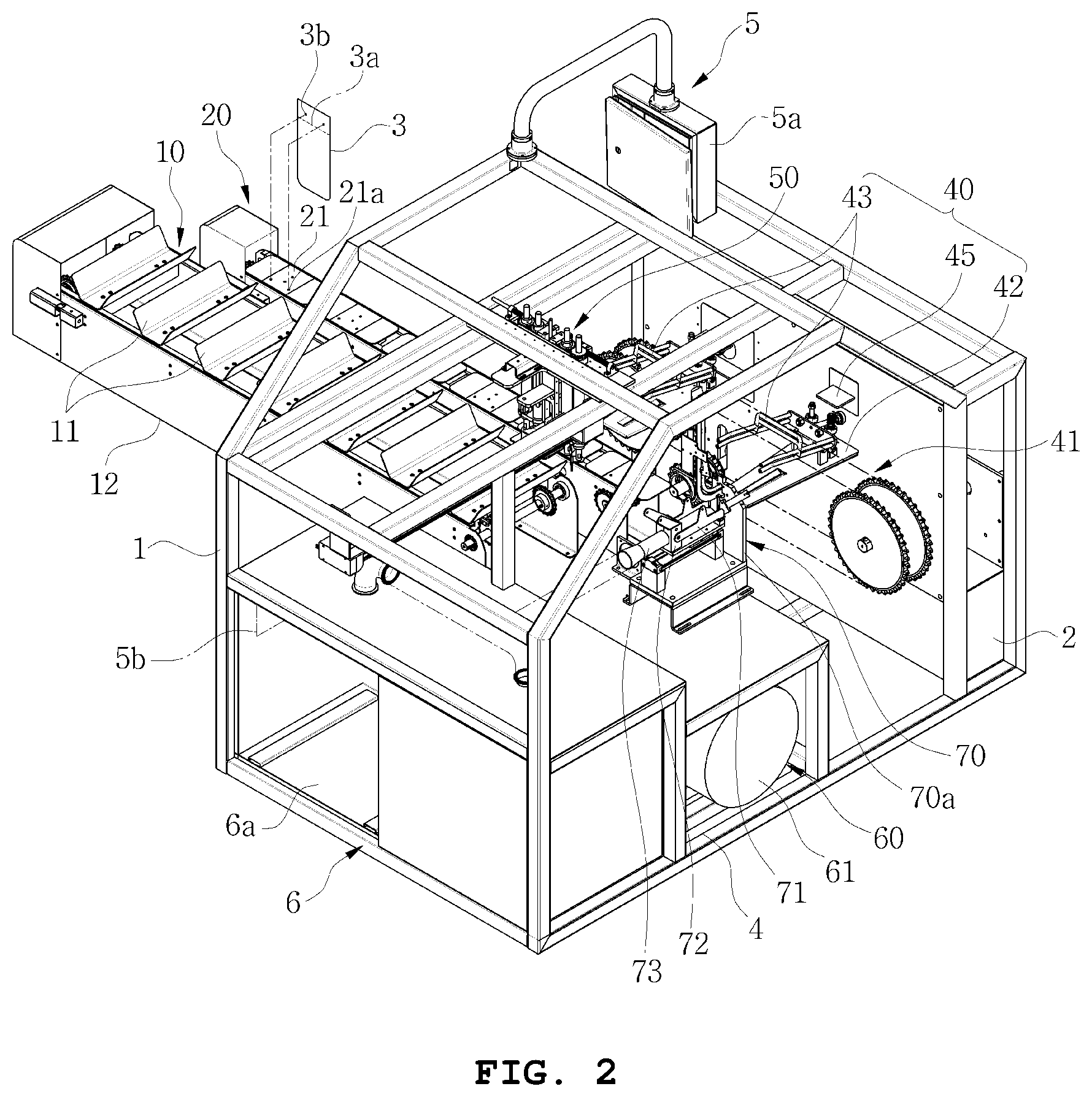
[0025] FIGS. 1 and 2 are perspective views illustrating an automatic packaging machine including circulation systems according to an exemplary embodiment;
[0026] FIGS. 3 and 4 are side views illustrating the automatic packaging machine including circulation systems according to an exemplary embodiment;
[0027] FIG. 5 is a bottom view illustrating the automatic packaging machine including circulation systems according to an exemplary embodiment; and
[0028] FIG. 6 is a front view illustrating the automatic packaging machine including circulation systems according to an exemplary embodiment.
DETAILED DESCRIPTION
[0029] The above and other objects, features and advantages of the present will be more clearly understood from the following detailed description when taken in conjunction with the accompanying drawings.
[0030] Reference should be made to the drawings, in which the same reference numerals and symbols may be used to designate the same or like components. In the following description of the present disclosure, detailed descriptions of known functions and components incorporated herein will be omitted in the case that the subject matter of the present disclosure may be rendered unclear thereby.
[0031] It will be understood that, while terms, such as "first," "second," "A," "B," "(a)," and "(b)," may be used herein to describe various elements, such terms are merely used to distinguish one element from another element. The substance, sequence, or order of such elements are not limited by these terms. It will be understood that when an element is referred to as being "connected to," "coupled to," or "joined to" another element, not only can it be "directly connected or coupled to" the other element, but it also can be "indirectly connected, coupled, or joined to" the other element via an "intervening" element.
[0032] First, an automatic packaging machine including circulation systems (hereinafter, referred to as an "automatic packaging machine") according to exemplary embodiments is an apparatus for automatically packaging individual products using triple circulation systems. The term "individual products" used herein may indicate poultry, such as chicken, duck, and quail, and may be other individual products that are packaged and sold individually or in blocks.
[0033] It is disclosed at the beginning that the following detailed description will be given with respect to poultry, the term "unpackaged products" used herein will mean poultry, and the term "packaged products" used herein will mean products finally packaged with packages.
[0034] A That is, the automatic packaging machine realizes continuous and automatic packaging using triple circulation systems comprised of an unpackaged product feeding circulation system, a package (or bag) feeding circulation system, and a packaged product circulation conveying system. In particular, the automatic packaging machine realizes continuous feeding of unpackaged products using the unpackaged product feeding circulation system, continuous feeding of packages using the package feeding circulation system, and conveyance of packaged products using the packaged product circulation conveying system.
[0035] In addition, two or more spaces for loading residuals when processing the scrap of unpackaged products are provided, so that continuous processing is possible without interruption. Furthermore, it is possible to increase the performance and speed of packaging by the development of a servo system, thereby significantly improving productivity.
[0036] In addition, it is possible to monitor situations of packaging in any places, such as a production site or an office, due to the development of Internet access and wired/wireless communications functions for a programmable logic controller (PLC). It is possible to update and repair PLC programs from any place in the world as long as the PLC is connected to the Internet. Furthermore, it is possible to easily perform after service (AS), field management, or the like, due to cameras disposed on the ceiling of the packaging machine or on the ceiling of the space in which the packaging machine is disposed.
[0037] Therefore, according to exemplary embodiments, it is possible to improve company competitiveness due to reliable manufacturing of products and improve target achievement rates due to reliable manufacturing efficiency.
[0038] Hereinafter, an exemplary embodiment of the present disclosure will be described in detail with reference to the accompanying drawings.
[0039] As illustrated in FIGS. 1 to 6, the automatic packaging machine according to an exemplary embodiment includes: an unpackaged product feeding circulation system 10 for conveying unpackaged products; a package (or bag) feeding circulation system for conveying packages 3 with which unpackaged products are packaged; a cylinder-shaped unpackaged product inserting unit 30 for inserting unpackaged products into the packages 3; a package opening unit 50 for opening a mouth 3a of each of the packages 3; and a packaged product circulation conveying system 40 for conveying packaged products. In addition, the automatic packaging machine may further include: a pneumatic unit 60 blowing air into each of the packages 3 to expand the mouth 3a of the package 3; and a product tight fitting unit 70 for causing the packages 3 to be tightly fitted to packaged products.
[0040] Each of the components of the automatic packaging machine may be provided and operated as a single unit or assembly in a space defined by a base frame 1 forming a basic framework, and such components are illustrated in the accompanying drawings. In addition, a power supply 2 may be disposed in the lower portion of the base frame 1 as an electric control panel to supply power to the components, and an operation unit may be disposed in the upper portion as a touch screen to control the components.
[0041] In addition, the automatic packaging machine includes a drive unit and a power transmission unit as a power source to move the triple circulation systems. The drive unit may be provided as a servomotor electrically connected to the power supply 2, while the power transmission unit may be provided as a chain, a gear module, and the like. Accordingly, in the automatic packaging machine, it is possible to control an intended speed and a moving distance, realize double or multiple actions, and adjust a start sped, an operating speed, and a stopping speed as intended. Various types of performance can be realized depending on the characteristics of products.
[0042] The unpackaged product feeding circulation system 10 is a mechanical apparatus to automatically transport individual unpackaged products, i.e. individuals of chicken, duck, quail, or the like. In the unpackaged product feeding circulation system 10, unpackaged product transport containers 11 made of, for example, stainless steel are attached to an unpackaged product transport conveyor 12 so as to circulate on the unpackaged product transport conveyor 12. Each of the unpackaged product transport containers 11 may have a V-shaped, rounded, or polygonal side-view geometry, with the upper portion being open. The unpackaged product transport conveyor 12 includes a chain, a gear module for driving the chain, and the like.
[0043] The unpackaged product transport containers 11 have the V-shaped, rounded, or polygonal side-view geometry, with the upper portion being open, such that a geometry suitable to the shape unpackaged products may be selected for use. The unpackaged product transport containers 11 are attached to the unpackaged product transport conveyor 12 at equal distances.
[0044] For example, unpackaged products may be fed by workers manually placing unpackaged products onto the unpackaged product transport containers 11 or using an automatic unpackaged product feeding system associated with an automatic unpackaged product feeding unit that may be implemented as a servo cylinder. In addition, the automatic unpackaged product feeding system may work in concert with the circulation system to facilitate continuous manufacturing.
[0045] In addition, water-absorbing cloth may be fed together with unpackaged products to be placed on top of the unpackaged product transport containers 11. The water-absorbing cloth may absorb blood plasma leaking from unpackaged products to improve sanitation in the product packaging process.
[0046] The package feeding circulation system 20 is disposed on one side of the unpackaged product feeding circulation system 10, and includes package loading plates 21 disposed on a package feeding conveyor 22 at equal distances from each other so as to circulate on the package feeding conveyor 22. The package feeding conveyor 22 is comprised of double chains made of, for example, stainless steel and a gear module or the like for driving the chains. Each of the package loading plates 21 has a pair of hooks 21a protruding upward to temporarily catch the mouth 3a of one package, of the packages 3, loaded thereon.
[0047] Each of the packages 3 is provided as a packaging plastic bag with the mouth 3a formed in one longitudinal end such that an unpackaged product is inserted thereinto in the longitudinal direction. The mouth 3a has a pair of holes 3b, such that a single package 3 or a bundle of about one-hundred packages 3 may be loaded on each of the package loading plates 21, caught by the pair of hooks 21a. The following description will be given with respect to a bundle of packages loaded on each of the package loading plates.
[0048] In the package feeding circulation system 20 transporting such bundles of packages, when a bundle of packages 3 loaded on one of the package loading plates 21 are exhausted, a photosensor or the like detects the exhaustion using. Then, the package feeding circulation system 20 automatically transports a next one of the package loading plates 21, on which a next bundle of packages 3 are loaded, to the designated position, so that the packaging operation can be performed continuously. That is, a continuous manufacturing process can be performed using the circulation system.
[0049] Here, each of the packages 3 must not be dislodged from the corresponding package loading plate 21 when the package 3 is being opened or when an unpackaged product is being inserted into the package 3, and must be removed from the package loading plate 21 when the packaging operation is completed and the packaged product is to be transported to a next section of the process. In this regard, a package holder may be provided on a side portion of the package feeding conveyor 22 to press and release a bundle of packages.
[0050] The unpackaged product inserting unit 30 is disposed above the unpackaged product feeding circulation system 10. The unpackaged product inserting unit 30 may include a pair of cylinders, which may be servo cylinders, pneumatic cylinders, or a combination thereof. In addition, a servo motor is used to adjust functions, such as a pushing distance, a pushing speed, and strength, as required, depending on the shape and weight of unpackaged products.
[0051] That is, the unpackaged product inserting unit 30 may be implemented as a double cylinder system to freely adjust the speed at which unpackaged products are inserted. For example, the unpackaged product inserting unit 30 may be implemented as a pair of servo cylinders, a combination of a single servo cylinder and a single pneumatic cylinder, or a pair of pneumatic cylinders. Accordingly, it is possible to provide various types of performance, such as adjustment of the speed at which unpackaged products are inserted, adjustment of the distance at which unpackaged products are pushed, and double or multiple actions.
[0052] The package opening unit 50 is disposed above the package feeding circulation system 20. The package opening unit 50 provides tunneling to an entrance to prevent a protrusion of an unpackaged product from being sandwiched between a upper guide 50a and a side guide 52. In addition, a pair of blades 51 are provided on the upper guide 50a to open the mouth 3a of each of the packages 3 by a grippers-like opening action.
[0053] The pair of blades 51 are driven in opposite directions by a servo motor to open the mouth 3a of each of the packages 3 by the grippers-like opening action. The blades 51 may be machined to have a singular curve to facilitate discharge of compressed air from the package 3.
[0054] In addition, the package opening unit 50 is configured to allow the blades 51 to easily enter each of the packages 3 through the mouth 3a while being movable back and forth to adjust the length of the blades 51 depending on the specification of the packages 3.
[0055] This is because the packages 3 cannot be prevented from being torn or dislodged during insertion of unpackaged products unless the blades 51 do not sufficiently enter the packages 3. In addition, to prevent the packages 3 from being dislodged during insertion of unpackaged products, a lift 53 for raising the lower portion of each of the packages 3 may be disposed on the side guide t2. The upper portion of the lift 53 may be disposed to be pivotable.
[0056] The pneumatic unit 60 includes an air intake unit 61 disposed in a lower space 4 defined by the base frame 1. The air intake unit 61 is implemented as a single blower, to which a valve is connected. A hose and a nozzle, acting as an air discharging unit, are connected to the valve. Air is blown toward the mouth 3a of each of the packages 3, opened by the blades 51, through the air discharging unit to widen the mouth 3a. In addition, air is evacuated from the inside of the package to cause the packages 3 to be tightly fitted to packaged products.
[0057] In addition, a three-way valve may be used to improve the vacuuming performance, which may be degraded by a difference in the diameter between an inlet and an outlet of the central portion of the blower. In this configuration, the three-way valve disposed on the outlet side of the blower allows air to be easily discharged at a point in time at which high vacuum is required. At the same time, suction force based on high vacuum necessary for vacuum suction in the mouth 3a of each of the packages 3, can be obtained.
[0058] That is, a vent system implemented using a three-way valve having the same size as a suction pipe is provided on a discharge line of the blower. This configuration can easily discharge air, thereby increasing vacuum-based suction force in the mouth 3a of each of the packages 3. Accordingly, it is possible to reduce the amount of power used and maximize vacuum-based suction force, so that air can be easily evacuated from the packages 3.
[0059] Here, it should be understood that an air compressor may be used as the air intake unit 61 in place of the blower to blow air to widen the mouth 3a of each of the packages 3.
[0060] The packaged product circulation conveying system 40 is disposed on one side of the package feeding circulation system 20. The packaged product circulation conveying system 40 includes a packaged product transport conveyor 41, packaged product support plates 42, and upper holders 43. The packaged product transport conveyor 41 includes double chains to support the weight and size of packaged products, a main gear driving the double chains, and the like. The packaged product support plates 42 are disposed on the packaged product transport conveyor 41 at equal distances from each other so as to circulate on the packaged product transport conveyor 41. The upper holders 43 are pivotably disposed above the packaged product support plates 42 to hold packaged products.
[0061] In addition, the packaged product circulation conveying system 40 further includes: coil springs 44 having elastic force to downwardly pivot the upper holders 43; and upper holder controllers disposed on a product transfer line, in positions above the upper holders 43, to be movable up and down, thereby upwardly pivoting the upper holders 43, respectively. Each of the upper holder controllers 45 is implemented as a combination of a cylinder and a linear cam.
[0062] That is, in order to transport packaged products through process steps, the packaged product support plates 42 are provided as bases designed to be suitable to packaged products, the springs are disposed on convex columns provided above the packaged product support plates 42, and the upper holders 43 are pivotably provided above the packaged product support plates 42 to hold packaged products. In addition, the operation of the upper holders 43 is controlled using the coil springs 44 and the upper holder controllers 45.
[0063] The packaged product circulation conveying system 40 presses and upwardly pivots the upper holders 43 using the upper holder controllers 45, for example, before entrance to a first section. After completion of insertion of products into the packages 3, the upper holder controllers 45 are moved upwardly by cylinders, so that the upper holders 43 are caused to pivot downwardly by the elastic force of the coil springs 44, thereby holding the packaged products.
[0064] Afterwards, when the packaged products are moved to the next section, i.e. the product tight fitting unit 70, the packages 3 are automatically tightly fitted to the packaged products.
[0065] Subsequently, when the packaged products are moved to the next section, i.e. a discharge operation, the upper holders 43 that have been holding the packages 3 are caused to pivot upwardly by the upper holder controllers 45, which are moved downwardly by the cylinders, so that the packaged products are discharged.
[0066] According to an exemplary embodiment as set forth above, it is possible to realize continuous and automatic manufacturing via continuous and automatic feeding of unpackaged products, continuous and automatic feeding of packages, and continuous and automatic feeding of packaged products using the triple circulation systems, thereby effectively improving productivity.
[0067] In addition, the product tight fitting unit 70 according to an exemplary embodiment is disposed on the line of the package feeding circulation system 20 to be operated in process steps undertaken after unpackaged products are inserted into the packages 3. The product tight fitting unit 70 may include a package entrance guide 70a, a vacuum suction unit 73, grippers 71, and a reciprocation unit 72. In addition, a package pushing unit, a binding unit, and a cutting unit may be added.
[0068] For example, packages 3 for wrapping in unpackaged products may have various types of specifications. Unpackaged products must be pushed into and tightly wrapped with the packages 3 to package products in suitable specifications, and unnecessary leftovers of the packages 3 must be cut off.
[0069] Accordingly, guides 70b may be disposed in upper and lower portions in a predetermined section through the packages 3 enter in order to prevent the mouth 3a of each of the packages 3 from being scattered. After the predetermined section, an air injection unit for injecting air supplied from, for example, the pneumatic unit 60 may be provided to facilitate the entrance of the mouth 3a of each of the packages 3 into the vacuum suction unit 73.
[0070] In addition, to easily grip the mouth 3a of each of the packages 3, the vacuum suction unit 73 may have the shape of an ellipse, such that side portions are expanded. The mouth 3a may be cut at an inclined angle, such that entering package 3 can be easily drawn by suction.
[0071] Thus, the mouth 3a of the package 3 that has entered the vacuum suction unit 73 is drawn into the vacuum suction unit 73. Afterwards, the grippers 71 grip the mouth 3a by pivoting, and at the same time, the reciprocation unit 72 backwardly draws the package 3. Accordingly, the packaged product in the package 3 is pushed inwardly while the package 3 is drawn.
[0072] In order to prevent portions of the package 3 from being scattered, a pusher is operated to push the entrance of the binding unit into the binding unit. When all of these operates are finished, the mouth 3a of the package 3 is bound with a clip or the like, and unnecessary leftovers of the package 3 are cut off.
[0073] Here, a function of cutting off the leftovers of the package 3 or a function of leaving the leftovers of the package 3 may be selected using a touchscreen 5a, i.e. a control unit.
[0074] According to exemplary embodiments, it is possible to automate the process of inserting a product into the package 3 using the product tight fitting unit 70 and tightly fitting the package 3 to the packaged product. Furthermore, after the mouth 3a is bound with a clip or the like, the process of cutting the leftovers can be automated. Accordingly, automated continuous manufacturing is possible, thereby significantly improving productivity.
[0075] In addition, the automatic packaging machine according to an exemplary embodiment may further include a product insertion guide unit, a loading unit 6, and a controller 5.
[0076] The product insertion guide unit includes a guide unit base, a package top end guide, and a package side guide. The height of the top end guide, as well as the lateral width of the side guide, is adjustable depending on the size of unpackaged products.
[0077] The loading unit 6 may include two or more loading chambers 6a each provided as a vacuum chamber by the base frame 1. The loading chambers 6a of the loading unit 6 can accommodate remainders, including leftovers of the packages 3, therein via vacuum suction. Accordingly, continuous manufacturing is possible.
[0078] For example, when a predetermined amount of remainders are accumulated in one of the loading chambers 6a, a sensor 6a, such as a photosensor, detects the accumulation of remainders. Then, the controller 5 automatically replaces the loading chamber filled with the remainders with the empty loading chamber by controlling three-way valves (not shown) connected to the loading chambers 6a.
[0079] As the loading chambers 6a are used alternately, the continuous process of treating remainders including leftovers can be undertaken without interruption.
[0080] Here, the loading unit 6 may be disposed, for example, within the automatic packaging machine, or may be disposed outside of the automatic packaging machine as required.
[0081] In addition, perforated boxes made of stainless steel may be provided within the loading chambers 6a, respectively, and specially-fabricated nets for treating remainders may be disposed within the perforated boxes to reduce times for treating remainders.
[0082] When a large amount of remainders including the leftovers of the packages 3, occurring during the packaging process of products, are accumulated in the perforated box, a large amount of time is necessary for the operation of removing the remainders from the perforated box.
[0083] Accordingly, when the nets for treating remainders are disposed within the perforated boxes, it is possible to easily detach the nets from the perforated boxes by raising the nets using fixing hooks provided on the corners of the nets. When a binding string provided on an inlet of the net for treating remainders is drawn, the net is quickly transformed into a sack of remainders. When the sack is removed from the perforated box, the treatment operation can be completely finished in a simple manner.
[0084] The controller 5 may include, for example, the touchscreen 5a, a programmable logic controller (PLC), four servo systems, the sensor 5b, and the like. The PLC may be provided with an Internet access function and a wireless communications function, in addition to a basic program control function, to be connected to an office and other intended places, as well as mobile devices, via a wired/wireless medium, so that an operator can check situations in real time.
[0085] As set forth above, the automatic packaging system according to exemplary embodiments can not only improve company competitiveness due to reliable manufacturing of products and improved productivity and improve target achievement rates due to reliable manufacturing efficiency, but also can be useful in terms of industrial safety and economic considerations.
[0086] Although the foregoing descriptions and the accompanying drawings have been presented in order to explain certain principles of the present disclosure in detail, the automatic packaging machine including circulation systems according to the present disclosure is not limited thereto. It will be understood that the terms "comprise", "include", and "have", used herein specify the presence of stated elements but do not preclude the presence or addition of any other elements unless explicitly noted. Unless otherwise defined, all terms including technical and scientific terms used herein have the same meaning as commonly understood by a person skilled in the art to which the present disclosure pertains. It will be further understood that terms, such as those defined in commonly used dictionaries, should be interpreted as having a meaning that is consistent with their meaning in the context of the relevant art, and will not be interpreted in an idealized or overly formal sense, unless defined expressly so herein.
[0087] The foregoing descriptions and the accompanying drawings have been presented in order to explain certain principles of the present disclosure. A person skilled in the art to which the present disclosure pertains could make many modifications and variations by combining, dividing, substituting for or changing elements without departing from the principle of the present disclosure. The foregoing embodiments disclosed herein shall be interpreted as being illustrative only, while not being limitative, of the principle and scope of the present disclosure. It should be understood that the scope of the present disclosure shall be defined by the appended claims and all of their equivalents fall within the scope of the present disclosure.
* * * * *
D00000
D00001
D00002
D00003
D00004
D00005
D00006
XML
uspto.report is an independent third-party trademark research tool that is not affiliated, endorsed, or sponsored by the United States Patent and Trademark Office (USPTO) or any other governmental organization. The information provided by uspto.report is based on publicly available data at the time of writing and is intended for informational purposes only.
While we strive to provide accurate and up-to-date information, we do not guarantee the accuracy, completeness, reliability, or suitability of the information displayed on this site. The use of this site is at your own risk. Any reliance you place on such information is therefore strictly at your own risk.
All official trademark data, including owner information, should be verified by visiting the official USPTO website at www.uspto.gov. This site is not intended to replace professional legal advice and should not be used as a substitute for consulting with a legal professional who is knowledgeable about trademark law.