Lifeboat Launch Control System
Milligan; John
U.S. patent application number 16/815124 was filed with the patent office on 2020-07-02 for lifeboat launch control system. The applicant listed for this patent is John Milligan. Invention is credited to John Milligan.
| Application Number | 20200207448 16/815124 |
| Document ID | / |
| Family ID | 66431790 |
| Filed Date | 2020-07-02 |


| United States Patent Application | 20200207448 |
| Kind Code | A1 |
| Milligan; John | July 2, 2020 |
LIFEBOAT LAUNCH CONTROL SYSTEM
Abstract
A lifeboat launch control system. The lifeboat launch control system has a wheel trunk that runs along the side of a ship. An axle box is vertically movable in the wheel trunk. The axle box has a pair of wheels on opposing sides of a bar. A shaft is removably inserted into the bar. The shaft is removable from the bar by a handle. When the shaft is removed from the bar, the lifeboat is released from the ship.
| Inventors: | Milligan; John; (Houston, TX) | ||||||||||
| Applicant: |
|
||||||||||
|---|---|---|---|---|---|---|---|---|---|---|---|
| Family ID: | 66431790 | ||||||||||
| Appl. No.: | 16/815124 | ||||||||||
| Filed: | March 11, 2020 |
Related U.S. Patent Documents
| Application Number | Filing Date | Patent Number | ||
|---|---|---|---|---|
| 16191957 | Nov 15, 2018 | 10618607 | ||
| 16815124 | ||||
| 62586750 | Nov 15, 2017 | |||
| Current U.S. Class: | 1/1 |
| Current CPC Class: | B63B 23/32 20130101; B63B 23/34 20130101; B63B 23/48 20130101; B63B 23/02 20130101; B63B 23/06 20130101 |
| International Class: | B63B 23/32 20060101 B63B023/32; B63B 23/06 20060101 B63B023/06; B63B 23/02 20060101 B63B023/02; B63B 23/34 20060101 B63B023/34; B63B 23/48 20060101 B63B023/48 |
Claims
1) A lifeboat launch control system comprising: an axle box disposed on a hull of a ship; the axle box having a bar with a pair of wheels disposed on a pair of opposite sides of the bar; an aperture in the bar, wherein a shaft extends therethrough and outward through the wheel trunk; a lifeboat interface disposed between a first end of the shaft and a second end of the shaft; a handle disposed on the second end of the shaft.
2) The lifeboat launch control system of claim 1, further comprising a spring disposed between the lifeboat interface and the handle, the spring tensioned and configured to expand outwardly to pull the shaft through the aperture.
3) The lifeboat launch control system of claim 1, wherein the wheel trunk comprises a pair of flexible flaps on a pair of opposing sides of the wheel trunk.
4) The lifeboat launch control system of claim 1, wherein a cover is movably disposed over a top end of the axel box.
5) The lifeboat launch control system of claim 1, wherein a drain is disposed at a bottom end of the axel box.
6) The lifeboat launch control system of claim 1, wherein a plurality of interior surfaces of the axel box are coated in anti-fouling paint.
7) The lifeboat launch control system of claim 1, further comprising at least one davit, wherein the at least one davit includes a cable in operable connection with the lifeboat.
8) The lifeboat launch control system of claim 7, wherein the at least one davit includes a bottom support arm extending therefrom.
9) The lifeboat launch control system of claim 1, wherein the lifeboat interface comprises a bumper disposed on an external surface thereof.
10) The lifeboat launch control system of claim 1, wherein the lifeboat interface comprises a hole through a sidewall of a lifeboat, wherein the hole is dimensioned to receive the shaft and pin.
Description
CROSS REFERENCE TO RELATED APPLICATIONS
[0001] This application claims the benefit of U.S. patent application Ser. No. 16/191,957 filed on Nov. 15, 2018 which claims the benefit of U.S. Provisional Application No. 62/586,750 filed on Nov. 15, 2017. The above identified patent applications are herein incorporated by reference in their entirety to provide continuity of disclosure.
BACKGROUND OF THE INVENTION
[0002] The present invention relates to a lifeboat launch control system configured to lower a lifeboat from a larger vessel into a body of water. More specifically, the present invention provides an interface for a ship and lifeboat that provides for safe and efficient lowering of a lifeboat. A wheel trunk is disposed in a hull of a ship and is configured to allow an axle box to pass therethrough. The axle box is operably connected to a shaft which can be actuated by an individual in a lifeboat to release the lifeboat from the axle box.
[0003] Typically, ships include at least one lifeboat for use in case of emergencies. Some ships may house additional smaller watercraft for various purposes. If an emergency occurs or if a smaller watercraft is to be released into the body of water, a cable system is typically used to lower the craft into the water. However, cable systems can provide problems due to a pendulum effect induced by the tide of the water. This danger is particularly notable where seas are rough due to their geographic location or due to severe weather. The aforementioned pendulum effect can create problems for a ship crew in that the smaller craft or lifeboat can be damaged or lost due to the swinging. Additionally, damage can be done to the ship itself if sufficient contact is made with the smaller craft. In addition to the costs associated with repairing such damage, swinging lifeboats and small watercraft can cause injuries to passengers or crew aboard both the larger and smaller watercrafts.
[0004] Due to the need to increase safety in the process of lowering lifeboats or small watercraft into a body of water, and the inefficiency of currently available lifeboat lowering systems, there is a defined need in the known art for a lifeboat lowering system that provides increased control o the user thereof.
SUMMARY OF THE INVENTION
[0005] In view of the foregoing disadvantages inherent in the known types of lifeboat lowering systems now present in the prior art, the present invention provides a lifeboat launch control system wherein the same can be utilized for providing convenience for the user when controlling the descent of a lifeboat into a body of water.
[0006] The present system comprises a wheel trunk. The wheel trunk is disposed in the hull of a ship. An axle box is disposed in the wheel trunk. The axle box has a bar with a pair of wheels disposed on a pair of opposite sides of the bar. A shaft extends through an aperture disposed in the bar and outward from the wheel trunk. The shaft has a first end and a second end, wherein a lifeboat interface is disposed therebetween. A pin is disposed in the end of the shaft. The aperture in the bar is shaped such that when the shaft is oriented to place the pin into a targeted position, the shaft can be freely moved through the bar. A handle is disposed on the second end of the shaft.
BRIEF DESCRIPTION OF THE DRAWINGS
[0007] Although the characteristic features of this invention will be particularly pointed out in the claims, the invention itself and manner in which it may be made and used may be better understood after a review of the following description, taken in connection with the accompanying drawings wherein like numeral annotations are provided throughout.
[0008] FIG. 1 shows a perspective view of an embodiment of the lifeboat launch control system.
[0009] FIG. 2 shows a perspective view of a wheel trunk of an embodiment of the lifeboat launch control system.
[0010] FIG. 3 shows a close-up view of the axle box and the shaft of an embodiment of the lifeboat launch control system.
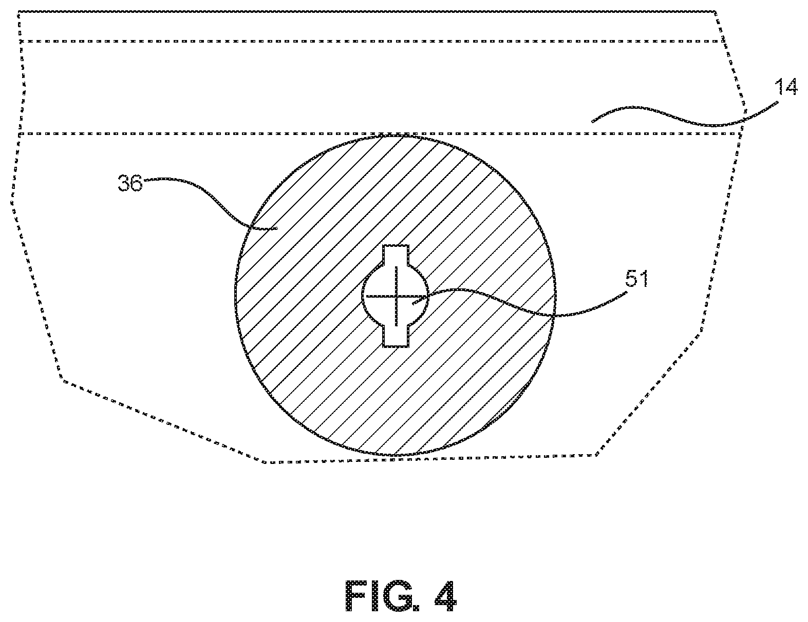
[0011] FIG. 4 shows a close-up view of the interface of an embodiment of the lifeboat launch control system.
DETAILED DESCRIPTION OF THE INVENTION
[0012] Reference is made herein to the attached drawings. Like reference numerals are used throughout the drawings to depict like or similar elements of the lifeboat launch control system. The figures are intended for representative purposes only and should not be considered to be limiting in any respect.
[0013] Referring now to FIG. 1, there is shown a perspective view of an embodiment of the lifeboat launch control system. The lifeboat launch control system 10 comprises a wheel trunk 11 disposed in a hull of a ship 12. In the illustrated embodiment, the wheel trunk 11 comprises three sidewalls and an open slot. The three sidewalls are planar and flat, such that a wheel can pass smoothly in an upward vertical direction and a downward vertical direction. An axle box 13 is disposed in the wheel trunk 11. The axle box 13 is configured to attach to a lifeboat 14. The axle box 13 attaches to the lifeboat 14 using a lifeboat interface. With the axle box 13 locked onto the lifeboat 14, the lifeboat 14 can be raised and lowered under control of the user.
[0014] In one embodiment, the lifeboat launch control system 10 further comprises at least one davit 15. As shown, the davit 15 comprises a base disposed on the deck of a boat and an arm extending towards the hull of the ship 12. In the illustrated embodiment, the davit 15 is hinged such that the arm can adjustably extend over the hull of the ship 12. The davit 15 includes an operably connected cable 16. The cable 16 is configured to attach to the lifeboat 14, such that the vertical position of the lifeboat relative to the ship 12 can be manipulated. In one embodiment, the cable 16 is operably connected to a winch, such that the cable 16 can be raised or lowered via actuation of the winch. The winch can be any automatic winch or manual winch. In a further embodiment, the davit 15 comprises a bottom support arm 17 extending therefrom. The bottom support arm 17 is configured to provide additional support to the lifeboat 14 when the lifeboat 14 is stored upon the deck of the ship 12. The stored position is defined in any configuration where the lifeboat 14 cannot be raised or lowered off the hull of the ship 12.
[0015] Referring now to FIG. 2, there is shown a perspective view of a wheel trunk of an embodiment of the lifeboat launch control system. The wheel trunk 11 has a top end 21 disposed at the top of the hull of the ship 12, and a bottom end 22 disposed at the base of the hull of the ship 12. In the illustrated configuration, the wheel trunk 11 extends linearly down the entire length of the hull of the ship 12. In other embodiments, the wheel trunk 11 is dimensioned to extend to the waterline, where the water meets the hull of the ship 12, such that the lifeboat is released precisely at water level.
[0016] In one embodiment, the wheel trunk 11 comprises a pair of flexible flaps 23 disposed on a pair of opposing sides of the wheel trunk 11. The pair of flexible flaps 23 are configured to prevent water from entering the wheel trunk 11 and potentially interfering with the operation of the axle box in the wheel trunk 11. In a further embodiment, the pair of flexible flaps 23 is made of neoprene rubber. In another embodiment, the pair of flexible flaps 23 are each hollow, such as to
D00000
D00001
D00002
D00003
D00004
XML
uspto.report is an independent third-party trademark research tool that is not affiliated, endorsed, or sponsored by the United States Patent and Trademark Office (USPTO) or any other governmental organization. The information provided by uspto.report is based on publicly available data at the time of writing and is intended for informational purposes only.
While we strive to provide accurate and up-to-date information, we do not guarantee the accuracy, completeness, reliability, or suitability of the information displayed on this site. The use of this site is at your own risk. Any reliance you place on such information is therefore strictly at your own risk.
All official trademark data, including owner information, should be verified by visiting the official USPTO website at www.uspto.gov. This site is not intended to replace professional legal advice and should not be used as a substitute for consulting with a legal professional who is knowledgeable about trademark law.