Flow Control For Agricultural Implement Pneumatic System
Millie; Stewart J. ; et al.
U.S. patent application number 16/234691 was filed with the patent office on 2020-07-02 for flow control for agricultural implement pneumatic system. This patent application is currently assigned to CNH Industrial Canada, Ltd.. The applicant listed for this patent is CNH Industrial Canada, Ltd.. Invention is credited to Stewart J. Millie, Andrew J. Williams.
| Application Number | 20200205337 16/234691 |
| Document ID | / |
| Family ID | 71121523 |
| Filed Date | 2020-07-02 |


| United States Patent Application | 20200205337 |
| Kind Code | A1 |
| Millie; Stewart J. ; et al. | July 2, 2020 |
FLOW CONTROL FOR AGRICULTURAL IMPLEMENT PNEUMATIC SYSTEM
Abstract
An agricultural air seeder planting unit incorporates control valves that split flow and change direction from supply to distribution hoses. The flow area of the control valves is automatically adjusted pneumatically by movement of a piston in response to total pressure to provide a uniform velocity flow from each of the control valves.
| Inventors: | Millie; Stewart J.; (Saskatoon, CA) ; Williams; Andrew J.; (Warman, CA) | ||||||||||
| Applicant: |
|
||||||||||
|---|---|---|---|---|---|---|---|---|---|---|---|
| Assignee: | CNH Industrial Canada, Ltd. Saskatoon CA |
||||||||||
| Family ID: | 71121523 | ||||||||||
| Appl. No.: | 16/234691 | ||||||||||
| Filed: | December 28, 2018 |
| Current U.S. Class: | 1/1 |
| Current CPC Class: | G05D 7/0153 20130101; A01C 7/20 20130101; A01C 7/042 20130101 |
| International Class: | A01C 7/20 20060101 A01C007/20; A01C 7/04 20060101 A01C007/04; G05D 7/01 20060101 G05D007/01 |
Claims
1. A pneumatic flow system for an agricultural implement, said pneumatic flow system comprising: a source of pressurized air; a system of hoses connected to said pressurized air source for distributing air to a plurality of delivery outlets, said system of hoses having at least one junction for splitting and changing air flow direction into at least a pair of flow paths to said delivery outlets; a control valve at said at least one junction fluidly connected to said system of hoses and displaceable to vary a flow area to said at least a pair of flow paths to said delivery outlets; a sensor for detecting pressure in said system of hoses immediately upstream of said control valve and generating a signal; and, a device receiving the signal from said sensor for displacing said control valve to a preselected flow area.
2. The pneumatic flow system as claimed in claim 1, wherein said sensor detects total air pressure of air immediately upstream of said control valve.
3. The pneumatic flow system as claimed in claim 1, wherein said directional change is approximately perpendicular to the flow of air entering said control valve.
4. The pneumatic flow system as claimed in claim 1, wherein said control valve comprises a housing having an inlet thereto and a valve element displaceable within said housing toward said inlet to vary the flow area from a minimum level when said valve element is fully inserted in said inlet and displaceable away from said inlet to increase the flow area.
5. The pneumatic flow system as claimed in claim 4, wherein said control valve housing defines an annular passage at the inlet thereof and said valve element has an annular cross-section projecting into said annular inlet passage.
6. The pneumatic flow system as claimed in claim 5, wherein said valve element has a generally conical cross-section with the tip of the cross-section positioned towards the upstream.
7. The pneumatic flow system as claimed in claim 6, wherein said sensor is positioned at least at the upstream tip of said valve element in said system of hoses.
8. The pneumatic flow system as claimed in claim 7, wherein said device receiving a signal from said sensor comprises a cylindrical chamber having a central opening for said displaceable valve element and a piston affixed to said valve element and displaceable within said chamber between a position in which the valve element defines the maximum flow through said valve passage and a position in which the valve is urged upstream to define a minimum flow position and wherein said sensor comprises a passage formed from the tip of said valve element to the end of the chamber opposite the tip of said valve element whereby the pressure at the tip of said valve element acts on and displaces said piston to decrease flow in response to an increase in pressure.
9. The pneumatic flow system as claimed in claim 8, wherein said control valve housing has a curved passage from said inlet to direct flow to said outlets and said valve element has a curved configuration.
10. A pneumatic flow control system comprising: a source of pressurized air; a supply hose receiving pressurized air from said pressurized air source; a control valve fluidly interposed in said hose and having a valve element displaceable toward said pressurized air source to reduce a flow area between the upstream and downstream side of said control valve; a sensor positioned on said displaceable valve element to measure total pressure of the air from said source of pressurized air and generate a signal; and a device receiving the signal from said sensor for displacing said valve element to a pre-selected flow area as a function of the total pressure of the air from said supply hose.
11. The pneumatic flow control system as claimed in claim 10, wherein said control valve comprises a housing having an annular passage forming the inlet to said control valve and said valve element is generally conical in shape and displaceable towards the annular inlet passage to reduce flow area.
12. The pneumatic flow control system as claimed in claim 11, wherein said sensor is positioned at least at the upstream tip of said displaceable valve element in said supply hose.
13. The pneumatic flow control system as claimed in claim 12, wherein said sensor generates an electrical output signal in response to said total pressure and said device comprises an actuator for displacing the valve element in response to said electrical signal.
14. The pneumatic flow control system as claimed in claim 13, further comprising a controller receiving the electrical signal from said sensor and controlling the actuator to displace the valve element to set the flow area to a predetermined flow quantity as a function of total pressure.
15. An agricultural implement for planting seeds in a moveable in a given direction for planting seeds in a field, said row crop planter comprising: a frame; a seed hopper mounted on said frame; a tool bar assembly supported by said frame and extending laterally relative to the direction of movement of said row crop planter; a plurality of planting units mounted on and spaced from one another along said tool bar assembly; a unit connected to and receiving material from said seed unit for metering material and conveying it in a pressurized air stream via sectional control; at least one hose connected to said metering and conveying unit for receiving material; a junction connected to said at least one hose for changing direction of flow and having a plurality of delivery outlets; hoses connecting each said plurality of delivery outlets to a corresponding planting unit; a control valve at said junction displaceable to vary a flow area to said plurality of delivery outlets; a sensor for detecting total air pressure in said at least one hose immediately upstream of said control valve and generating a signal; and, a device receiving the signal from said sensor for displacing said control valve to a pre-selected flow area.
16. The agricultural implement as claimed in claim 15, wherein said change of direction is approximately at a right angle.
17. The agricultural implement as claimed in claim 16, wherein said control valve comprises a housing having an annular inlet connected to said at least one hose and said valve element has an annular cross-section and is generally conical and displaceable into and through said annular inlet valve passage for reducing the flow area into said control valve housing.
18. The agricultural implement as claimed in claim 17, wherein said device receiving the signal comprises a cylindrical chamber formed in said control valve housing and having a central opening for said displaceable valve element and a piston affixed to the end of said valve element within said chamber, said piston being displaceable between a position in which the valve element projects through said passage and has a minimum flow area and a position away from the passage for providing a maximum flow area.
19. The agricultural implement as claimed in claim 18, wherein said valve element has a passage extending from the tip of said valve element into said cylindrical chamber for applying total pressure to said piston so that increase in total pressure urges said piston towards a position reducing air flow through said annular passage.
20. The agricultural implement as claimed in claim 18, wherein said control valve housing has a curved annular inlet passage to direct flow to said right angle directions and said valve element is curved at the point entering said curved annular inlet passage.
Description
FIELD OF THE INVENTION
[0001] The present invention relates to a pneumatic control system and, more specifically, to such a system used in agricultural implements.
BACKGROUND OF THE INVENTION
[0002] Modern seeding agricultural implements provide the function of distributing bulk seeds from an onboard hopper past a metering system to a series of hoses or conduits to individual planting units that are spaced laterally on a toolbar trailing behind a tractor. Seeding units provide a furrow of appropriate depth and distribute the seeds into the furrow from the respective hoses and then cover the hole up by an additional component. In order to appropriately distribute the individual seeds through the network of hoses, a pneumatic system provides a flow of pressurized air through the hoses to the individual seeding units.
[0003] In such an implement, it is important to have uniform flow throughout the pneumatic system. In many cases the conduits are split into branches and the flow therethrough becomes even more complicated because of an effective increase in cross-sectional airflow which thus causes the decrease in velocity. The air flow performance issues are further complicated by variations in configurations and in temporary conditions such as when sectional control is engaged wherein hoses may be partially blocked by debris. All of these factors act to present the possibility of variations in velocity between the individual planting units which can have an impact on overall accuracy of the seed spacing. When planters are manufactured with ever increasing lateral widths, the problems become even more pronounced.
[0004] Accordingly, what is needed in the art is a system for providing uniform flow through the pneumatic passages in an agricultural implement and other pneumatic systems.
SUMMARY OF THE INVENTION
[0005] The invention provides control valves within a system having a plurality of pneumatic flow passages to provide uniform and preselected flow.
[0006] In one form, the disclosure is a pneumatic flow system for an agricultural implement with a source of pressurized air and a system of hoses connected to the pressurized air source for distributing air and seeds to a plurality of delivery outlets. The system of hoses has at least one junction for splitting and changing airflow direction into at least a pair of flow paths. A control valve at the junction is displaceable to vary the flow area to the pair of flow paths and a sensor detects an air pressure immediately upstream of the control valve and generates a signal to a device which displaces the control valve to a preselected flow area.
[0007] In another form, the disclosure is a pneumatic flow control system with a source of pressurized air and a tube receiving pressurized air from the pressurized air source. A control valve is interposed in the tube and has a valve element displaceable towards the pressurized air source to reduce flow area between the upstream and downstream side of the control valve. A sensor positioned on the displaceable valve element measures total pressure of the pressurized air and generates a signal which is used by a device receiving the signal for displacing the valve element to a preselected flow area.
[0008] In still another form, the disclosure an agricultural implement for planting seeds and movable in a given direction for planting seeds in a field. The row crop planter includes a frame, a seed hopper mounted on the frame, a toolbar supported by the frame and extending laterally relative to the direction of movement of the row crop planter. A plurality of planting units are mounted on and spaced from one another along the toolbar. A unit is connected to and receives material from the seed unit for metering material and conveying it in a pressurized air stream. At least one hose is connected to the metering and conveying unit for receiving material. A junction is connected to at least one hose for changing the direction of flow and having a plurality of outlets. Hoses connect a plurality of delivery outlets to a corresponding planting unit. A control valve at the junction is displaceable to vary the flow area to the plurality of delivery outlets and a sensor detects the air pressure immediately upstream of the control valve and generates a signal. A device receives the signal from the sensor for displacing the control valve to a preselected flow area.
[0009] One advantage of the disclosure is to provide a simplified yet effective control of air through the plurality of hoses in a pneumatic conveying system.
[0010] Another advantage is to ensure uniform distribution of seeds and improved accuracy in an air seeder planting unit.
BRIEF DESCRIPTION OF THE DRAWINGS
[0011] For the purpose of illustration, there are shown in the drawings certain embodiments of the present invention. It should be understood, however, that the invention is not limited to the precise arrangements, dimensions, and instruments shown Like numerals indicate like elements throughout the drawings. In the drawings:
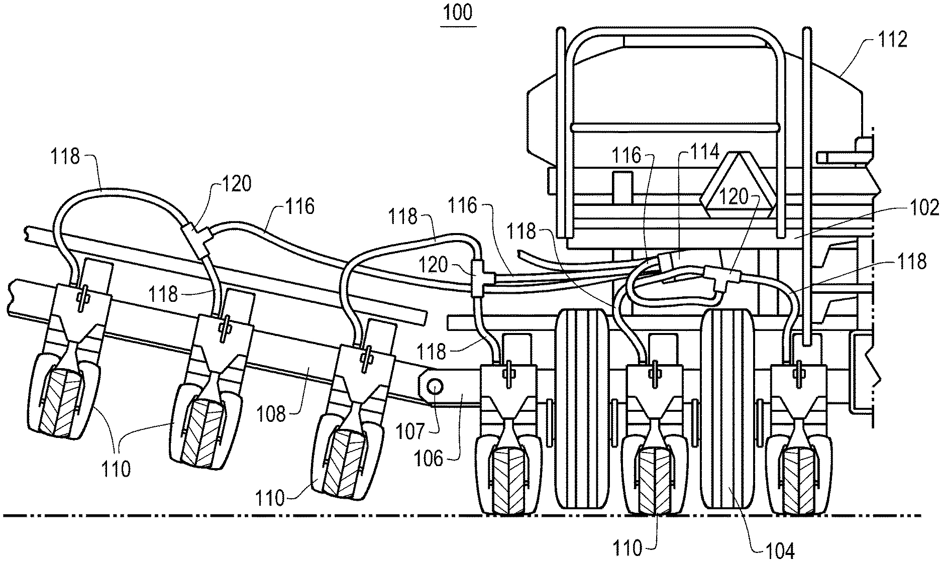
[0012] FIG. 1 shows an agricultural implement with which the present disclosure may be used;
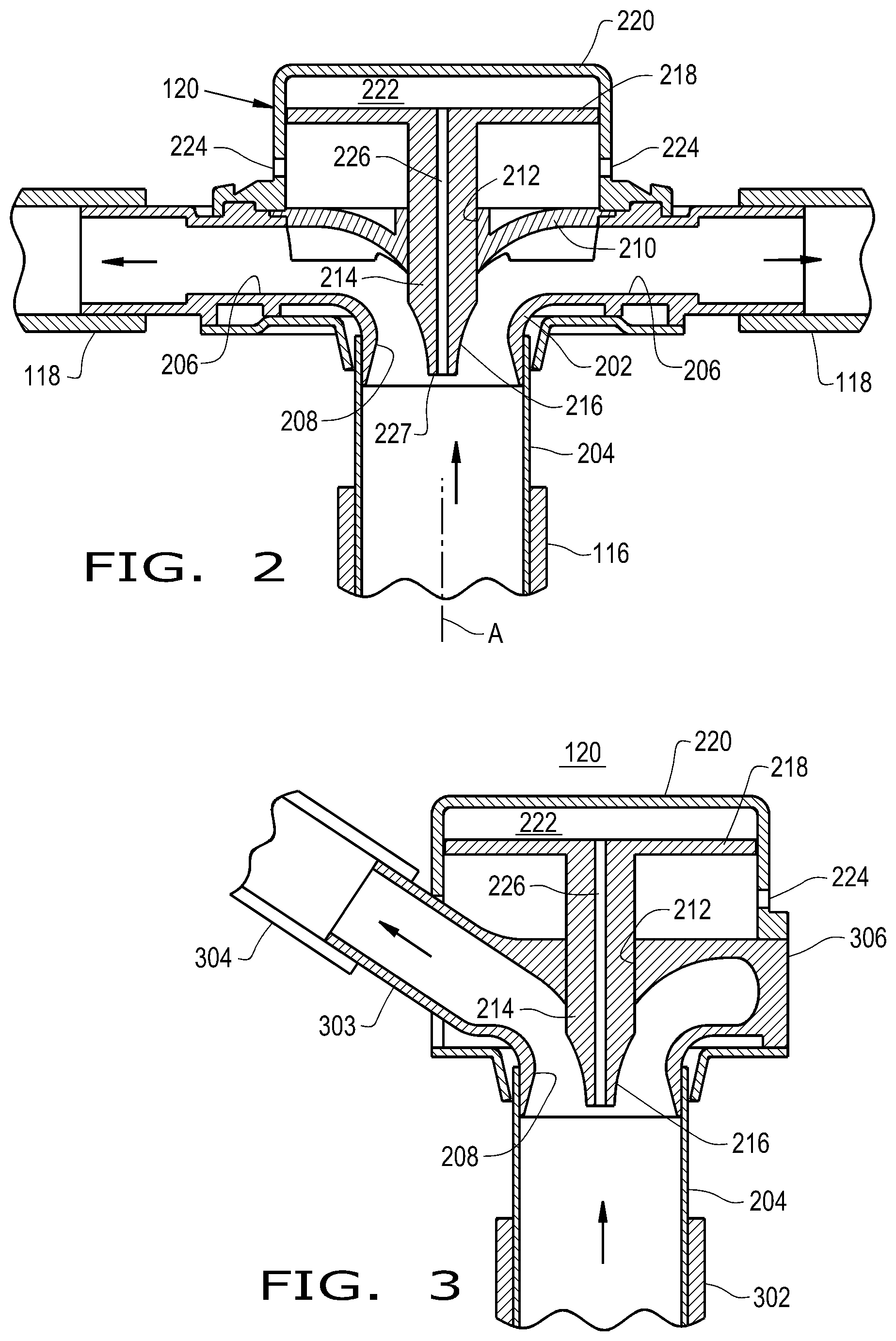
[0013] FIG. 2 is a control valve incorporated in the agricultural implement of FIG. 1;
[0014] FIG. 3 is an alternative embodiment of the control valve incorporated in FIG. 1; and
[0015] FIG. 4 is still another alternative of a control valve for use with the agricultural planter of FIG. 1.
DETAILED DESCRIPTION OF THE INVENTION
[0016] Referring first to FIG. 1, there is shown rear view of an agricultural implement 100. The agricultural implement 100 includes a frame 102 having ground support wheels 104 for permitting mobile movement of the implement 100 over the ground in a field operation for seeding and also in a transport mode. The ground support wheels 104 are adjustable to establish an appropriate height for the implement during the planting operation and at a higher elevation during the transport between planting fields. A center tool bar 106 is mounted to frame 102 and extends transversely relative to the direction of movement, which is into the drawing in FIG. 1. Pivoting outer tool bars 108 are connected to the center tool bar by an appropriate pivotal connection 107 so that when they are extended the pivoting tool bars 108 act as a lateral extension of center tool bar 106. A plurality of planting units 110 are mounted on and spaced from one another along the center tool bar 106 and the pivoting tool bars 108. As known in the art, the planting units 110 form a trough in a field at an appropriate depth for the seeds which are then introduced in a metered fashion to the bottom of the trough. The planting units 110 also have components that cover the trough for proper seed placement. Details of the mechanism unit for the planting units 110 are not shown to enable a clear focus on the present disclosure.
[0017] A bulk seed hopper 112 is mounted on frame 102 and provides seeds in a bulk fashion. A seed metering assembly 114 receives seeds from bulk seed hopper 112 and meters them and displaces them by a utilizing a pressurized air source as is well known in the art. The details of this mechanism are not discussed to enable a clearer focus on the present disclosure. The seed metering assembly 114 distributes the seeds in an air stream and introduces them into a plurality of supply houses 116 for distribution to the planting units 110. The supply hoses 116 extend each to a control valve 120 which changes the direction of the flow and diverts it into a pair of distribution hoses 118 which in turn connect to the planting units 110 for discharge of seeds into a trough formed by the planting units 110.
[0018] In prior art air seeding units, the rate of flow through the various supply and distribution hoses is essential for accurate metering of the seeds at the planting units to replicate as close as possible the metering performed by the seed metering assembly 114. In practice, this becomes difficult because of the many variations in connections of the conduits, their distance from the seed metering unit, sectional controls and in local disturbances. Any such variation can cause a lack of uniformity which can impact on the metering effectiveness at the planting units 110. In accordance with the present disclosure, the control valve 120 illustrated in FIG. 2 provides a uniform distribution of flow. The control valve 120 includes a housing 202 that has an inlet 204 connected to a supply hose 116 and outlets 206 connected to distribution hoses 118. A curved annular inlet passage 208 is formed in housing 202 to provide a directional transition from the flow emanating from supply hose 116 to the distribution hoses 118. As illustrated, the transition is through 90.degree., however it should be apparent to those skilled in the art that the change in direction may take other forms. Housing 202 has an insert 210 which provides a smooth transition to the outlets 206 and which is generally annular in shape as viewed in the direction of axis A of the inlet 204. A through opening 212 is provided in insert 210 and receives a valve element 214 displaceable in a direction towards and away from inlet 204. Valve element 214 has a nose 216 which is curved and which aligns with the curvature of the insert 210 to provide a smooth transition of flow to the distribution hoses 118.
[0019] Valve element 214 is connected to a piston 218 displaceable in a housing 220 to provide a pressure chamber 222 on the side of the piston that is downstream from the flow entering inlet passage 208. Bleed holes 224 are provided on the housing 220 opposite to the side of piston 218 exposed to pressure chamber 222 so that ambient air may freely enter or leave that side of the housing 220. A pressure passage 226 is longitudinally provided in valve element 214 and extends from the nose 227 of valve element 214 to pressure chamber 222. As illustrated, housing 220, piston 218 and valve element 214 are shown as cylindrical in shape. The area of the piston 218 exposed to air in pressure chamber 222 is substantially larger than the area of the valve element exposed to air pressure adjacent inlet 208. Many different ratios may be provided to select the proper air flow.
[0020] In practice, air under pressure along with seeds flowing from supply hose 116 enters inlet passage 208 and the total pressure at the nose 227 of valve element 214 is applied to pressure chamber 222. The pressure sensed at the nose 227 includes the static pressure and more importantly the total pressure which reflects the energy and the velocity of air entering through inlet passage 208. If the pressure increases to a level above what is desired, the increased pressure in pressure chamber 222 causes the piston 218 to displace towards an upstream direction thus reducing the flow area past the curved inlet passage 208. As illustrated in FIG. 2, the valve element 214 is approximately at a mid position between a condition where the valve element 214 is retracted providing a maximum flow area and a condition where it is fully extended providing a minimum flow area. The valve element 214 then is displaced to a point that restricts flow thus decreasing the total pressure and allowing the piston 218 to displace further into the pressure chamber 222 and thus increase flow area and flow to an appropriate level. The valve assembly 120 utilizes straight forward fluid dynamic principals to provide an automatic and preselected flow rate throughout the supply and distribution hoses of the agricultural implement 100. Whenever conditions change, the control valves 120 automatically vary the inlet area so that a uniform air flow velocity may be employed throughout the system.
[0021] The control valve 120 shown in FIG. 2 has a pair of outlet passages. It should be apparent to those skilled in the art that there may be more or less passages having a flow area and flow rate controlled. Therefor, more than two passages may be employed and in the case of FIG. 3, a single passage may be controlled. In this case, the control valve 120 is the same as in FIG. 3 except that a single outlet 303 is provided from a control valve 120 housing 306 for connection to an outlet hose 304. A supply hose 302 provides a flow of air into the control valve 120. The operation of the valve is substantially identical to that of the illustration in FIG. 2 in that pressure chamber 222 receives total pressure from supply hose 302 to displace the valve element 214 as needed to control flow area and thus the rate of flow through the outlet hose 304. The angle between the axis of supply hose 302 and outlet hose 304 is approximately 120.degree. but can be any angle that allows clearance around the housing 220 while allowing the pressure passage 226 to sense the total pressure of air at the control valve 120 inlet.
[0022] The illustrations in FIGS. 2 and 3 show the manipulation of a control valve in purely pneumatic, mechanical fashion. The embodiment shown in FIG. 4 shows the implementation of the control valve in an electro-mechanical configuration. In this case, a valve element 401 is displaceable within opening 212 and is displaceable into the curved inlet passage 208. An appropriate pressure sensor 402 is positioned at a nose 403 of a valve element 401 or upstream in supply hose 116 to sense total pressure within the inlet passage 208. The sensor 402 generates a signal proportional to total pressure and feeds it through line 404 to a controller 406. Controller 406 utilizes the signal from sensor 402 via line 404 so that appropriate correcting signals are fed via a line 407 to an appropriate actuator 408 which displaces valve element 401 in an upstream and downstream direction through mechanical connection 410. The actual implementation of the control circuitry and mechanism is not shown to simplify the focus on the present disclosure. The valve element 401 is displaced to control flow area and thus velocity and flow rate as in the case of the control valves of FIGS. 2 and 3 in that an increase in pressure causes the valve element 401 to be displaced to reduce the flow and a decrease in pressure causes the valve element 401 to be displaced in a downstream direction to increase flow area and thus the flow rate.
[0023] These and other advantages of the present invention will be apparent to those skilled in the art from the foregoing specification. Accordingly, it is to be recognized by those skilled in the art that changes or modifications may be made to the above-described embodiments without departing from the broad inventive concepts of the invention. It is to be understood that this invention is not limited to the particular embodiments described herein, but is intended to include all changes and modifications that are within the scope and spirit of the invention.
* * * * *
D00000
D00001
D00002
D00003
XML
uspto.report is an independent third-party trademark research tool that is not affiliated, endorsed, or sponsored by the United States Patent and Trademark Office (USPTO) or any other governmental organization. The information provided by uspto.report is based on publicly available data at the time of writing and is intended for informational purposes only.
While we strive to provide accurate and up-to-date information, we do not guarantee the accuracy, completeness, reliability, or suitability of the information displayed on this site. The use of this site is at your own risk. Any reliance you place on such information is therefore strictly at your own risk.
All official trademark data, including owner information, should be verified by visiting the official USPTO website at www.uspto.gov. This site is not intended to replace professional legal advice and should not be used as a substitute for consulting with a legal professional who is knowledgeable about trademark law.