Connecting Element For Connecting A Heating Energy Generating Element To A Carrier Element Of A Cooking Hob
VERDOLIVA; Valerio ; et al.
U.S. patent application number 16/619742 was filed with the patent office on 2020-06-25 for connecting element for connecting a heating energy generating element to a carrier element of a cooking hob. This patent application is currently assigned to Electrolux Appliances Aktiebolag. The applicant listed for this patent is ELECTROLUX APPLIANCES AKTIEBOLAG. Invention is credited to Massimo BANZATO, Laurent JEANNETEAU, Filippo MILANESI, Alwin NEUKAMM, Claudio PAOLINI, Agostino ROSSATO, Valerio VERDOLIVA.
| Application Number | 20200205241 16/619742 |
| Document ID | / |
| Family ID | 59034585 |
| Filed Date | 2020-06-25 |


| United States Patent Application | 20200205241 |
| Kind Code | A1 |
| VERDOLIVA; Valerio ; et al. | June 25, 2020 |
CONNECTING ELEMENT FOR CONNECTING A HEATING ENERGY GENERATING ELEMENT TO A CARRIER ELEMENT OF A COOKING HOB
Abstract
The present invention relates to a connecting element (10) for connecting a heating energy generating element (24) to a carrier element (26) of a cooking hob. The connecting element (10) includes an engagement portion (12) connectable to a receiving portion of the heating energy generating element (24) and/or the carrier element (26). Further, the present invention relates a cooking hob with a heating energy generating element (24) and a carrier element (26).
| Inventors: | VERDOLIVA; Valerio; (Forli, IT) ; NEUKAMM; Alwin; (Rothenburg ob der Tauber, DE) ; PAOLINI; Claudio; (Forli, IT) ; MILANESI; Filippo; (Forli, IT) ; JEANNETEAU; Laurent; (Forli, IT) ; BANZATO; Massimo; (Forli, IT) ; ROSSATO; Agostino; (Forli, IT) | ||||||||||
| Applicant: |
|
||||||||||
|---|---|---|---|---|---|---|---|---|---|---|---|
| Assignee: | Electrolux Appliances
Aktiebolag Stockholm SE |
||||||||||
| Family ID: | 59034585 | ||||||||||
| Appl. No.: | 16/619742 | ||||||||||
| Filed: | May 25, 2018 | ||||||||||
| PCT Filed: | May 25, 2018 | ||||||||||
| PCT NO: | PCT/EP2018/063755 | ||||||||||
| 371 Date: | December 5, 2019 |
| Current U.S. Class: | 1/1 |
| Current CPC Class: | H05B 2206/022 20130101; H05B 6/1209 20130101; H05B 6/1245 20130101; F24C 7/067 20130101 |
| International Class: | H05B 6/12 20060101 H05B006/12; F24C 7/06 20060101 F24C007/06 |
Foreign Application Data
| Date | Code | Application Number |
|---|---|---|
| Jun 9, 2017 | EP | 17175262.9 |
| Jul 17, 2017 | EP | 17181577.2 |
Claims
1. A connecting element for connecting a heating energy generating element to a carrier element of a cooking hob, comprising a first engagement portion connectable to a receiving portion of the heating energy generating element and/or the carrier element.
2. The connecting element according to claim 1, wherein the first engagement portion is a snap-fit portion and the receiving portion is a cut-out, wherein the snap-fit portion and the cut-out form a snap-in mechanism.
3. The connecting element according to claim 1, further comprising a spring portion arrangeable between the heating energy generating element and the carrier element, so that the spring portion provides a distance between the heating energy generating element and the carrier element.
4. The connecting element according to claim 1, further comprising a groove enclosing at least partially the connecting element, said groove being arranged between the first engagement portion and the spring portion.
5. The connecting element according to claim 4, wherein the groove is engageable with the cut-out of the heating energy generating element.
6. The connecting element according to claim 3, further comprising a groove enclosing at least partially the connecting element, wherein the spring portion is funnel-shaped and has a diameter that increases with distance from the first engagement portion and the groove.
7. The connecting element according to claim 1, wherein the first engagement portion is formed as a truncated pyramid.
8. The connecting element according to claim 1, further comprising a groove enclosing at least partially the connecting element, and a through hole having an axis that extends perpendicular to the groove, the through hole being adapted for receiving an elongated element of the carrier element extending perpendicular to a plane of said carrier element.
9. The connecting element according to claim 1, further comprising a further engagement portion extending opposite to the first engagement portion, wherein said further engagement portion is connectable to a receiving portion of the carrier element.
10. The connecting element according to claim 9, wherein the further engagement portion is a further snap-fit portion, while the receiving portion of the carrier element is a cut-out, so that the further snap-fit portion and the cut-out form a snap-in mechanism.
11. The connecting element according to claim 9, wherein the spring portion includes at least two wings arranged at opposite sides, wherein said wings extend outwards and away from the first engagement portion.
12. The connecting element according to claim 11, wherein the connecting element is formed as a profile section and includes two parallel grooves, wherein a profile axis extends parallel to said grooves, the first engagement portion comprising a clearance hole extending parallel to the profile axis.
13. A cooking hob comprising a heating energy generating element, a carrier element, and the connecting element according to claim 1.
14. The cooking hob according to claim 13, wherein the heating energy generating element includes a plurality of receiving portions adapted for receiving the engagement portion, wherein said receiving portion is engaged or engageable with a groove enclosing at least partially the connecting element.
15. The cooking hob according to claim 13, wherein the carrier element includes a plurality of receiving portions adapted for receiving a further engagement portion of the connecting element.
16. The cooking hob according to claim 13, wherein the carrier element includes a plurality of bent sheet metal fingers, wherein said bent sheet metal fingers are penetrable into or penetrate a through hole of the connecting element.
17. The cooking hob according to claim 13, comprising at least three said connecting elements per heating energy generating element and/or per carrier element.
18. The cooking hob according to claim 13, comprising one said heating energy generating element per carrier element, wherein each said carrier element includes three said connecting elements.
19. The cooking hob according to claim 13, comprising two said heating energy generating elements per carrier element, wherein each said carrier element includes four said connecting elements.
20. An induction cooking hob comprising an induction coil supported on a coil carrier by a connecting element, a cooking panel arranged at a top side of said cooking hob, and alignment means to fix a lateral position of said connecting element on said coil carrier to fix a lateral position of said connecting element thereon; said connecting element being a single-piece part comprising a snap-fit portion extending upward above a coil plate of said induction coil through a cut-out therein, a spring portion extending downward below said coil plate, and a groove extending perpendicular to a longitudinal axis of the connecting element, said coil plate being received and engaged in said groove, said snap-fit portion having a lateral dimension that at least partially decreases with increased distance from said groove, said spring portion resting on said coil carrier to thereby support the induction coil thereon, said spring portion being resilient thereby pushing the induction coil upward toward and against said cooking panel; said snap-fit portion and said alignment means being adapted to facilitate interconnection of said induction coil to said coil carrier via said connecting element via compression of said elements along a common single axis to facilitate efficient assembly thereof, said connecting element acting as a spacer that prohibits direct physical contact between said coil carrier and said induction coil, said induction cooking hob being devoid of steel springs for supporting said induction coil above said coil carrier.
Description
[0001] The present invention relates to a connecting element for connecting a heating energy generating element to a carrier element of a cooking hob. In particular, the present invention relates to a connecting element for connecting an induction coil to a coil carrier of an induction cooking hob. Further, the present invention relates to a cooking hob with at least one heating energy generating element and at least one carrier element. In particular, the present invention relates to an induction cooking hob with at least one induction coil and at least one coil carrier.
[0002] The fastening of an induction coil on a coil carrier of an induction cooking hob requires usually several elements. For example, a metal spring element is arranged between the induction coil and the coil carrier in order to push said induction coil towards a cooking panel arranged on the top side of the induction cooking hob. Further, at least one fastening element is provided for connecting the induction coil, the coil carrier and/or the spring element.
[0003] It is an object of the present invention to provide a connecting element for connecting a heating energy generating element to a carrier element of a cooking hob, which allows a reliable connection between the heating energy generating element and the carrier element by low complexity.
[0004] This and other objects are achieved by the connecting element according to claim 1.
[0005] According to the present invention, a connecting element for connecting a heating energy generating element to a carrier element of a cooking hob is provided, wherein the connecting element includes an engagement portion connectable to a receiving portion of the heating energy generating element and/or the carrier element.
[0006] According to the present invention it is particularly advantageous that the connecting element including the engagement portion. Said engagement portion may be easily connected to the receiving portion of the heating energy generating element and/or the carrier element.
[0007] In a preferred embodiment, the connecting element is provided for an induction cooking hob. Accordingly, it is preferred that the heating energy generating element is an induction coil. Additionally or alternatively, the carrier element is a heating energy generating element carrier, particularly an induction coil carrier.
[0008] Preferably, the connecting element is provided for an induction cooking hob, wherein the heating energy generating element is an induction coil, while the carrier element is a coil carrier.
[0009] Preferably, the engagement portion is a snap-fit portion.
[0010] Further, the receiving portion may be a cut-out, wherein preferably the snap-fit portion and the cut-out form a snap-in mechanism.
[0011] Moreover, the connecting element may be made of an elastic and/or insulating material.
[0012] In particular, the connecting element is formed as a single-piece part.
[0013] Preferably, the connecting element includes a spring portion arrangeable between the heating energy-generating element and the carrier element, so that the spring portion provides a distance between the heating energy-generating element and the carrier element.
[0014] Further, the connecting element may include at least one groove enclosing at least partially the connecting element, wherein preferably the at least one groove is arranged between the engagement portion and the spring portion.
[0015] Additionally, the groove is engageable with the receiving portion of the heating energy generating element, in particular with the cut-out of the induction coil.
[0016] Preferably, the elastic and/or insulating material is selected from the group of plastic, silicone and rubber.
[0017] According to one embodiment the spring portion is funnel-shaped, wherein the diameter of the funnel-shaped spring portion increases with the distances from the engagement portion, e.g. the snap-fit portion, and the groove.
[0018] For example, the engagement portion, e.g. the snap-fit portion, is formed as a truncated pyramid.
[0019] Further, the connecting element may include at least one through hole, wherein the axis of said through hole extends perpendicular to the groove.
[0020] Preferably, the through hole is adapted for receiving an element of the carrier element, in particular an elongated element of the carrier element extending perpendicular to a plane of said carrier element.
[0021] According to another embodiment the connecting element includes a further engagement portion extending opposite to the engagement portion, wherein preferably said further engagement portion is connectable to a receiving portion of the carrier element.
[0022] For example, the further engagement portion is a further snap-fit portion, while the receiving portion of the carrier element is a cut-out, so that the further snap-fit portion and the cut-out form a snap-in mechanism.
[0023] Alternatively, the spring portion includes at least two wings arranged at opposite sides, wherein said wings extend outwards and away from the engagement portion.
[0024] Further, the connecting element may be formed as a profile section and includes two parallel grooves, wherein the profile axis extends parallel to said grooves.
[0025] Moreover, the engagement portion may include a clearance hole extending parallel to the profile axis.
[0026] Further, the present invention relates to a cooking hob with at least one heating energy generating element and at least one carrier element, in particular an induction cooking hob with at least one induction coil and at least one coil carrier, wherein the cooking hob comprises at least one connecting element mentioned above.
[0027] In particular, the heating energy generating element includes a plurality of receiving portions, e.g. cut-outs, adapted for receiving the engagement portion, e.g. the snap-fit portion, wherein said receiving portion is engaged or engageable with the groove.
[0028] Additionally, the carrier element may include a plurality of receiving portions, e.g. cut-outs, adapted for receiving the further engagement portion, e.g. the further snap-fit portion.
[0029] Alternatively, the carrier element includes a plurality of bent sheet metal fingers, wherein said bent sheet metal fingers are penetrable into or penetrate the through hole of the connecting element.
[0030] Furthermore, the cooking hob comprises at least one, preferably at least three connecting elements per cooking hob. Particularly it is preferred that the cooking hob comprises at least one heating energy generating element with at least one, preferably at least three connecting elements per the heating energy generating element. Additionally or alternatively, it is also preferred that the cooking hob comprises a carrier element with at least one, preferably at least three connecting elements per the carrier element.
[0031] For example, the cooking hob comprises a carrier element for one heating energy generating element, wherein preferably the carrier element includes three connecting elements.
[0032] According to another example, the cooking hob comprises a carrier element with two heating energy generating elements, wherein preferably the carrier element includes four connecting elements.
[0033] According to still another example, the cooking hob comprises a carrier element with four heating energy generating elements per the carrier element, wherein preferably the carrier element includes three, preferably four, connecting elements.
[0034] Novel and inventive features of the present invention are set forth in the appended claims.
[0035] The present invention will be described in further detail with reference to the drawing, in which
[0036] FIG. 1 illustrates a schematic perspective view of a connecting element according to a first embodiment of the present invention,
[0037] FIG. 2 illustrates a further schematic perspective view of the connecting element according to the first embodiment of the present invention,
[0038] FIG. 3 illustrates a schematic bottom view of the connecting element according to the first embodiment of the present invention,
[0039] FIG. 4 illustrates a schematic sectional side view of the connecting element according to the first embodiment of the present invention,
[0040] FIG. 5 illustrates a schematic sectional front view of the connecting element according to the first embodiment of the present invention,
[0041] FIG. 6 illustrates a schematic perspective view of the connecting element according to a second embodiment of the present invention,
[0042] FIG. 7 illustrates a schematic bottom view of the connecting element according to the second embodiment of the present invention,
[0043] FIG. 8 illustrates a schematic sectional side view of the connecting element according to the second embodiment of the present invention,
[0044] FIG. 9 illustrates a schematic sectional front view of the connecting element according to the second embodiment of the present invention,
[0045] FIG. 10 illustrates a schematic perspective view of the connecting element according to a third embodiment of the present invention,
[0046] FIG. 11 illustrates a schematic front view of the connecting element according to the third embodiment of the present invention,
[0047] FIG. 12 illustrates a schematic front view of the connecting element according to a fourth embodiment of the present invention,
[0048] FIG. 13 illustrates a schematic front view of the connecting element according to a fifth embodiment of the present invention,
[0049] FIG. 14 illustrates a schematic perspective view of the connecting element interconnected between an induction coil and a coil carrier according to the first embodiment of the present invention,
[0050] FIG. 15 illustrates a schematic perspective sectional view of the connecting element interconnected between the induction coil and the coil carrier according to the first embodiment of the present invention,
[0051] FIG. 16 illustrates a schematic perspective view of the connecting element interconnected between the induction coil and the coil carrier according to the third embodiment of the present invention, and
[0052] FIG. 17 illustrates a schematic perspective sectional view of the connecting element interconnected between the induction coil and the coil carrier according to the third embodiment of the present invention.
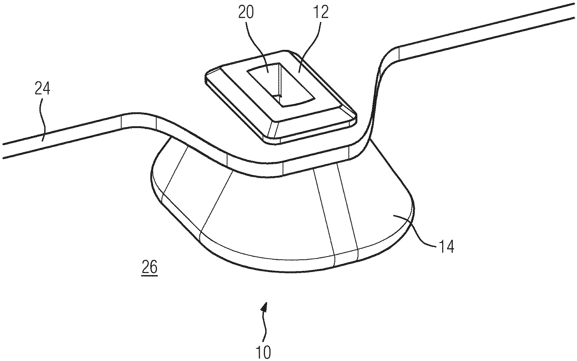
[0053] FIG. 1 illustrates a schematic perspective view of a connecting element 10 according to a first embodiment of the present invention. The connecting element 10 is made of an elastic material and/or insulating material. Preferably, the connecting element 10 is made of plastic, silicone or rubber.
[0054] The connecting element 10 includes a snap-fit portion 12 and a spring portion 14. The snap-fit portion 12 is substantially formed as a truncated pyramid, while the spring portion 14 is substantially funnel-shaped. A groove 16 is formed between the snap-fit portion 12 and the spring portion 14. In this example, the groove 16 encloses completely the connecting element 10. The cross-section of the snap-fit portion 12 decreases with the distance from the groove 16. The diameter of the funnel-shaped spring portion 14 increases with the distance from the groove 16. Further, the connecting element 10 includes a through hole 20. The axis of said through hole 20 extends perpendicular to the groove 16.
[0055] In this example, the connecting element 10 is provided for connecting an induction coil 24 to a coil carrier 26 of an induction cooking hob, wherein the opening of the funnel-shaped spring portion 14 is aligned on the coil carrier 26. In general, the connecting element is provided for connecting a heating energy generating element 24 to a carrier element 26 of a cooking hob. Usually, the coil carrier 26 is a horizontal sheet of the induction cooking hob. The snap-fit portion 12 is penetrable into a cut-out of the induction coil 24. Preferably, said cut-out is rectangular. For example, the cut-out is formed in an aluminium sheet of the induction coil 24. The groove 16 of the connecting element 10 is engaged or engageable with the cut-out of the induction coil 24.
[0056] FIG. 2 illustrates a further schematic perspective view of the connecting element 10 according to the first embodiment of the present invention. FIG. 2 clarifies the funnel-shaped structure of the spring portion 14. The elastic material of the connecting element 10 on the one hand and the funnel-shaped spring portion 14 on the other hand allow resilient properties of said spring portion 14.
[0057] FIG. 3 illustrates a schematic bottom view of the connecting element 10 according to the first embodiment of the present invention. FIG. 2 clarifies the cross-section of the through hole 20 and the structure of the spring portion 14.
[0058] FIG. 4 and FIG. 5 illustrate schematic sectional views of the connecting element 10 according to the first embodiment of the present invention. FIG. 4 and FIG. 5 clarify the shapes of the snap-fit portion 12, the spring portion 14 and the groove 16. The snap-fit portion 12 forms the truncated pyramid and the spring portion 14 is substantially funnel-shaped. The groove 16 extends between said snap-fit portion 12 and spring portion 14 and encloses completely the connecting element 10. The groove 16 extends perpendicular to the axis of the through hole 20.
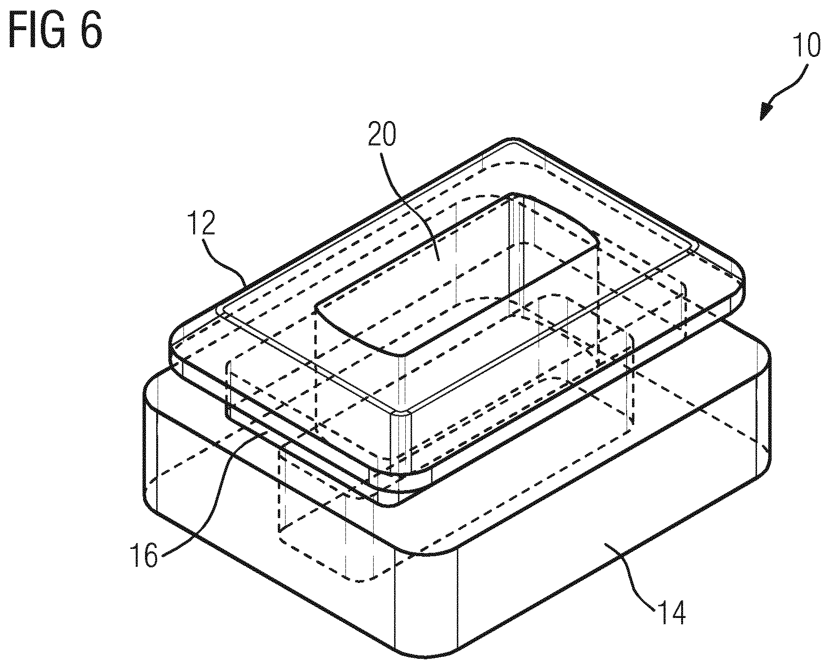
[0059] FIG. 6 illustrates a schematic perspective view of the connecting element 10 according to a second embodiment of the present invention. The connecting element 10 is made of an elastic material, preferably of silicone or rubber.
[0060] The connecting element 10 includes the snap-fit portion 12 and the spring portion 14. The snap-fit portion 12 is substantially formed as the truncated pyramid. The spring portion 14 is formed as a hollow cuboid with open top and bottom sides. The groove 16 is formed between the snap-fit portion 12 and the spring portion 14 and encloses completely the connecting element 10. The cross-section of the snap-fit portion 12 decreases with the distance of said snap-fit portion 12 from the groove 16. The connecting element 10 includes the through hole 20, wherein the axis of said through hole 20 extends perpendicular to the groove 16.
[0061] The connecting element 10 of the second embodiment is provided for connecting the induction coil 24 to the coil carrier 26 of the induction cooking hob. The opening of the cuboid-shaped spring portion 14 is aligned on the coil carrier 26. The snap-fit portion 12 is penetrable into the cut-out of the induction coil 24. Preferably, said cut-out is rectangular. The groove 16 is engaged or engageable with the cut-out of the induction coil 24.
[0062] FIG. 7 illustrates a schematic bottom view of the connecting element 10 according to the second embodiment of the present invention. FIG. 7 clarifies the cross-section of the through hole 20 and the structure of the spring portion 14.
[0063] FIG. 8 and FIG. 9 illustrate schematic sectionals views of the connecting element 10 according to the second embodiment of the present invention. FIG. 8 and FIG. 9 clarify the shapes of the snap-fit portion 12, the spring portion 14 and the groove 16. The snap-fit portion 12 forms the truncated pyramid. The groove 16 extends between said snap-fit portion 12 and spring portion 14 and encloses completely the connecting element 10. The groove 16 extends perpendicular to the axis of the through hole 20.
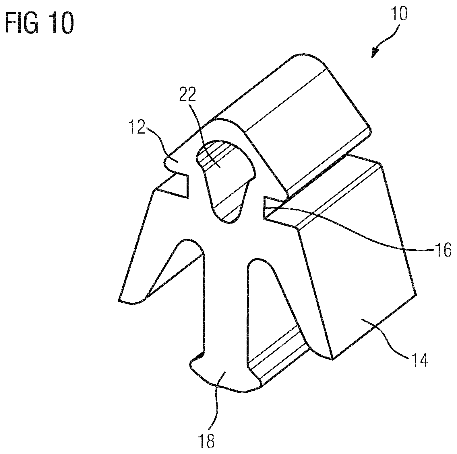
[0064] FIG. 10 illustrates a schematic perspective view of the connecting element 10 according to a third embodiment of the present invention. The connecting element 10 is also made of an elastic material, preferably silicone or rubber.
[0065] The connecting element 10 of the third embodiment has the shape of a profile section. The cross-section of said connecting element 10 along a profile axis is constant. The connecting element 10 includes the snap-fit portion 12 and the spring portion 14. The snap-fit portion 12 is substantially formed as a prism extending along the profile axis. The width of the snap-fit portion 12 decreases with the distance from the spring portion 14. The spring portion 14 includes two wings arranged at opposite sides. Said wings extend outwards and away from the snap-fit portion 12. Two grooves 16 are formed between the snap-fit portion 12 and the spring portion 14. Said grooves 16 extend parallel to each other and are arranged at opposite sides. The grooves 16 extend parallel to the profile axis. Each groove 16 is arranged between the snap-fit portion 12 and one wing of the spring portion 14.
[0066] Additionally, the connecting element 10 includes a further snap-fit portion 18 arranged opposite to the snap-fit portion 12. Moreover, the snap-fit portion 12 includes a clearance hole 22 extending along the profile axis. Thus, the snap-fit portion 12 is a flexible hose with a triangular cross-section.
[0067] The connecting element 10 is provided for connecting the induction coil 24 to the coil carrier 26 of the induction cooking hob, wherein the distal ends of the wings of the spring portion 14 are aligned on the coil carrier 26. The snap-fit portion 12 is penetrable into the cut-out of the induction coil 24. Preferably, said cut-out is rectangular. For example, the cut-out may be formed in the aluminium sheet of the induction coil 24. The grooves 16 of the connecting element 10 are engaged or engageable with the cut-out of the induction coil 24. The further snap-fit portion 18 is penetrable into a cut-out of the coil carrier 24. Preferably, said cut-out is rectangular.
[0068] FIG. 11 illustrates a schematic front view of the connecting element 10 according to the third embodiment of the present invention. FIG. 11 clarifies the cross-section of the connecting element 10 of the third embodiment. The snap-fit portion 12 is hollow and hence easily deformable. Thus, the snap-fit portion 12 can be inserted into the cut-out of the induction coil 24 by little effort.
[0069] FIG. 12 illustrates a schematic front view of the connecting element 10 according to a fourth embodiment of the present invention. Also the connecting element 10 of the fourth embodiment has the shape of a profile section.
[0070] The connecting element 10 includes the snap-fit portion 12 and the spring portion 14. The snap-fit portion 12 is substantially formed as a cuboid extending along the profile axis. The spring portion 14 includes two wings arranged at opposite sides. Said wings extend outwards and away from the snap-fit portion 12. Two grooves 16 are formed between the snap-fit portion 12 and the spring portion 14. The grooves 16 extend parallel to each other and are arranged at opposite sides. The grooves 16 extend along the profile axis. Each groove 16 is arranged between the snap-fit portion 12 and one wing of the spring portion 14. The connecting element 10 includes the further snap-fit portion 18 arranged opposite to the snap-fit portion 12. The further snap-fit portion 18 is penetrable into the cut-out of the coil carrier 24.
[0071] FIG. 13 illustrates a schematic front view of the connecting element 10 according to a fifth embodiment of the present invention. The connecting element 10 of the fifth embodiment also has the shape of a profile section.
[0072] The connecting element 10 includes the snap-fit portion 12, the spring portion 14, the grooves 16 and the further snap-fit portion 12. The snap-fit portion 12 is substantially formed as a cuboid extending along the profile axis. The spring portion 14 includes two wings arranged at opposite sides. Said wings extend outwards and away from the snap-fit portion 12. Two grooves 16 are formed between the snap-fit portion 12 and the spring portion 14. The grooves 16 extend parallel to each other and are arranged at opposite sides. The grooves 16 extend along the profile axis. Each groove 16 is arranged between the snap-fit portion 12 and one wing of the spring portion 14. The connecting element 10 includes the further snap-fit portion 18 arranged opposite to the snap-fit portion 12, wherein said further snap-fit portion 18 is penetrable into the cut-out of the coil carrier 24.
[0073] FIG. 14 illustrates a schematic perspective view of the connecting element 10 interconnected between an induction coil 24 and a coil carrier 26 according to the first embodiment of the present invention.
[0074] The induction coil 24 is arranged above the coil carrier 26. The connecting element 10 is arranged between the induction coil 24 and the coil carrier 26. The connecting element 10 penetrates the induction coil 24, wherein the snap-fit portion 12 of said connecting element 10 is arranged above the induction coil 24. The spring portion 14 of the connecting element 10 is arranged between the induction coil 24 and the coil carrier 26. The groove 16 of the connecting element 10 engages with the cut-out in the induction coil 24. For example, the cut-out of the induction coil 24 is formed in an aluminium disk of said induction coil 24. The spring portion 14 of the connecting element 10 is supported by the coil carrier 26.
[0075] FIG. 15 illustrates a schematic perspective sectional view of the connecting element 10 interconnected between the induction coil 24 and the coil carrier 26 according to the first embodiment of the present invention. At least one connecting element 10 is provided for connecting the induction coil 24 to the coil carrier 26. For example, three connecting elements 10 are provided for connecting the induction coil 24 to the coil carrier 26.
[0076] The snap-fit portion 12 of the connecting element 10 is arranged above the induction coil 24, while the spring portion 14 of the connecting element 10 is arranged beneath said induction coil 24 and above the coil carrier 26. The groove 16 of the connecting element 10 engages with the cut-out in the induction coil 24. The spring element 14 of the connecting element 10 is supported by the coil carrier 26.
[0077] A bent sheet metal finger 28 of the coil carrier 26 penetrates the through hole 20 of the connecting element 10. A resulting cutting 30 from preparing the bent sheet metal finger 28 remains in the coil carrier 26. Said cutting 30 is arranged beneath the spring element 14 of the induction coil 24. The bent sheet metal finger 28 of the coil carrier 26 extends vertically upwards. The connection between the bent sheet metal finger 28 and the through hole 20 effects that the connecting element 10 cannot be displaced parallel to the coil carrier 26.
[0078] The snap-fit portion 12 of the connecting element 10 and the cut-out in the induction coil 24 form a snap-in mechanism, so that the connecting element 10 and the induction coil 24 are fixed to each other. The connection of the bent sheet metal finger 28 and the through hole 20 guarantee the correct placement of the induction coil 24 and the connecting element 10 on the coil carrier 26. Further, the connecting element 10 acts as a spacer and avoids that the metallic induction coil 24 and the metallic coil carrier 26 enter in contact. Moreover, the spring portion 14 of the connecting element 10 pushes the induction coil 24 towards against a cooking panel arranged on the top side of the induction cooking hob.
[0079] The connecting elements 10 of the first and second embodiments do not require any steel spring elements because of the spring portion 14. The connecting elements 10 of the first and second embodiments do not require any space beneath the coil carrier 26. The connecting elements 10 of the first and second embodiments may be for already existing induction coils 24 and coil carriers 26.
[0080] FIG. 16 illustrates a schematic perspective view of the connecting element 10 interconnected between the induction coil 24 and the coil carrier 26 according to the third embodiment of the present invention.
[0081] The induction coil 24 is arranged above the coil carrier 26. The connecting element 10 is fastened at the induction coil 24 and at the coil carrier 26. The connecting element 10 is penetrated in the induction coil 24, wherein the snap-fit portion 12 of said connecting element 10 is arranged above the induction coil 24. The spring portion 14 of the connecting element 10 is arranged between the induction coil 24 and the coil carrier 26. The grooves 16 of the connecting element 10 engage with the cut-out in the induction coil 24. For example, the cut-out of the induction coil 24 is formed in an aluminium disk of said induction coil 24. The distal ends of the wings of the spring portion 14 are supported by the coil carrier 26. The further snap-fit portion 18 of the connecting element 10 penetrates the cut-out 32 in the coil carrier 26.
[0082] FIG. 17 illustrates a schematic perspective sectional view of the connecting element 10 interconnected between the induction coil 24 and the coil carrier 26 according to the third embodiment of the present invention. At least one connecting element 10 is provided for connecting the induction coil 24 to the coil carrier 26. For example, three connecting elements 10 are provided for connecting the induction coil 24 to the coil carrier 26.
[0083] The connecting element 10 is fastened at the induction coil 24 and at the coil carrier 26. The snap-fit portion 12 of said connecting element 10 is fastened above the induction coil 24, while the spring portion 14 of the connecting element 10 is arranged between the induction coil 24 and the coil carrier 26. The grooves 16 of the connecting element 10 engage with the cut-out in the induction coil 24. The distal ends of the wings of the spring portion 14 are supported by the coil carrier 26. The further snap-fit portion 18 of the connecting element 10 penetrates the cut-out 32 in the coil carrier 26.
[0084] The connecting elements 10 of the third to fifth embodiments allow the fastening of said connecting elements 10 on the coil carrier 26 without the bent sheet metal fingers 28. The cut-out 32 in the coil carrier 26 is sufficient for fixing the connecting element 10 by the further snap-fit portion 18. The concept of the cut-outs 32 in the coil carrier 26 allows a modular coil carrier 26. A plurality of arrangements of cut-out 32 in the coil carrier 26 allows that one coil carrier 26 is provided for different induction cooking hobs.
[0085] The snap-fit portion 12 and the further snap-fit portion 18 of the connecting element 10 allow an automatic assembling of the induction coil 24 on the coil carrier 26 by an assembling line. The connecting element 10 with the snap-fit portion 12 and the further snap-fit portion 18 allows the assembling of the induction coil 24 on the coil carrier 26 by a robot. The snap-fit portion 12 and the cut-out in the induction coil 24 form the snap-in mechanism between the induction coil 24 and the connecting element 10, while the further snap-fit portion 18 and the cut-out 32 in the coil carrier 26 form a snap-in mechanism between the coil carrier 26 and the connecting element 10.
[0086] Although illustrative embodiments of the present invention have been described herein with reference to the accompanying drawings, it is to be understood that the present invention is not limited to those precise embodiment, and that various other changes and modifications may be affected therein by one skilled in the art without departing from the scope or spirit of the invention. All such changes and modifications are intended to be included within the scope of the invention as defined by the appended claims.
LIST OF REFERENCE NUMERALS
[0087] 10 connecting element [0088] 12 snap-fit portion [0089] 14 spring portion [0090] 16 groove [0091] 18 further snap-fit portion [0092] 20 through hole [0093] 22 clearance hole [0094] 24 induction coil [0095] 26 coil carrier [0096] 28 bent sheet metal finger [0097] 30 cutting [0098] 32 cut-out
* * * * *
D00000
D00001
D00002
D00003
D00004
D00005
D00006
D00007
D00008
D00009
D00010
XML
uspto.report is an independent third-party trademark research tool that is not affiliated, endorsed, or sponsored by the United States Patent and Trademark Office (USPTO) or any other governmental organization. The information provided by uspto.report is based on publicly available data at the time of writing and is intended for informational purposes only.
While we strive to provide accurate and up-to-date information, we do not guarantee the accuracy, completeness, reliability, or suitability of the information displayed on this site. The use of this site is at your own risk. Any reliance you place on such information is therefore strictly at your own risk.
All official trademark data, including owner information, should be verified by visiting the official USPTO website at www.uspto.gov. This site is not intended to replace professional legal advice and should not be used as a substitute for consulting with a legal professional who is knowledgeable about trademark law.