Harq Feedback Configuration Techniques For Broadband Wireless Communication Networks
HE; HONG ; et al.
U.S. patent application number 15/751451 was filed with the patent office on 2020-06-25 for harq feedback configuration techniques for broadband wireless communication networks. This patent application is currently assigned to INTEL IP CORPORATION. The applicant listed for this patent is INTEL IP CORPORATION. Invention is credited to ALEXEI DAVYDOV, SEUNGHEE HAN, HONG HE, HWAN-JOON KWON, GANG XIONG.
| Application Number | 20200204328 15/751451 |
| Document ID | / |
| Family ID | 55182537 |
| Filed Date | 2020-06-25 |


View All Diagrams
| United States Patent Application | 20200204328 |
| Kind Code | A1 |
| HE; HONG ; et al. | June 25, 2020 |
HARQ FEEDBACK CONFIGURATION TECHNIQUES FOR BROADBAND WIRELESS COMMUNICATION NETWORKS
Abstract
HARQ feedback configuration techniques for broadband wireless communication networks are described. In one embodiment, for example, an apparatus may comprise a memory and logic for user equipment (UE), at least a portion of the logic implemented in circuitry coupled to the memory, the logic to identify a hybrid automatic repeat request (HARQ) bundling window associated with a received downlink (DL) scheduling command, identify one or more HARQ feedback configuration parameters based on HARQ feedback configuration information comprised in the DL scheduling command, the one or more identified HARQ feedback configuration parameters to include a physical uplink control channel (PUCCH) format for use in transmission of HARQ feedback for the HARQ feedback bundling window, the logic to generate the HARQ feedback for transmission to an evolved node B (eNB) according to the PUCCH format. Other embodiments are described and claimed.
| Inventors: | HE; HONG; (BEIJING, CN) ; DAVYDOV; ALEXEI; (NIZHNY NOVGOROD, RU) ; HAN; SEUNGHEE; (SAN JOSE, CA) ; XIONG; GANG; (BEAVERTON, OR) ; KWON; HWAN-JOON; (SANTA CLARA, CA) | ||||||||||
| Applicant: |
|
||||||||||
|---|---|---|---|---|---|---|---|---|---|---|---|
| Assignee: | INTEL IP CORPORATION SANTA CLARA CA |
||||||||||
| Family ID: | 55182537 | ||||||||||
| Appl. No.: | 15/751451 | ||||||||||
| Filed: | December 24, 2015 | ||||||||||
| PCT Filed: | December 24, 2015 | ||||||||||
| PCT NO: | PCT/US2015/000441 | ||||||||||
| 371 Date: | February 8, 2018 |
Related U.S. Patent Documents
| Application Number | Filing Date | Patent Number | ||
|---|---|---|---|---|
| 62203673 | Aug 11, 2015 | |||
| Current U.S. Class: | 1/1 |
| Current CPC Class: | H04W 84/042 20130101; H04L 5/0055 20130101; H04L 1/1812 20130101; H04L 1/1864 20130101 |
| International Class: | H04L 5/00 20060101 H04L005/00; H04L 1/18 20060101 H04L001/18 |
Claims
1. An apparatus, comprising: a memory; and logic for user equipment (UE), at least a portion of the logic implemented in baseband circuitry coupled to the memory, the logic to: determine a number of bits of hybrid automatic repeat request (HARQ) feedback to be included in control information to be provided to an evolved node B (eNB); determine whether a physical uplink control channel (PUCCH) format 3 can accommodate the determined number of bits of HARQ feedback; and in response to a determination that the PUCCH format 3 cannot accommodate the determined number of bits of HARQ feedback: generate the control information according to a second PUCCH format; and send the control information to radio frequency (RF) circuitry for transmission to the eNB via a PUCCH resource identified based on a value contained in downlink control information (DCI) received from the eNB.
2. The apparatus of claim 1, the value to be comprised in a transmit power control (TPC) field of the DCI.
3. The apparatus of claim 1, the value to comprise a two-bit value.
4. The apparatus of claim 1, the logic to: identify a PUCCH resource value that corresponds to the value contained in the DCI; and identify the PUCCH resource based on the PUCCH resource value.
5. The apparatus of claim 1, the HARQ feedback to comprise feedback for downlink (DL) data transmissions to the UE via a plurality of aggregated component carriers.
6. The apparatus of claim 1, the logic to determine that the PUCCH format 3 cannot accommodate the determined number of bits of HARQ feedback when the determined number of bits of HARQ feedback exceeds 21 bits.
7. The apparatus of claim 1, the logic to: in response to a determination that the PUCCH format 3 can accommodate the determined number of bits of HARQ feedback, generate the control information according to the PUCCH format 3, for transmission to the eNB via a PUCCH resource identified based on a value contained in downlink control information (DCI) received from the eNB.
8. The apparatus of claim 1, the logic to generate the control information for transmission to the eNB via a PUCCH of a primary cell of the UE.
9. The apparatus of claim 1, comprising radio frequency (RF) circuitry coupled to the baseband circuitry, the RF circuitry to generate RF signals for transmission to the eNB, the RF signals to comprise the control information.
10. At least one computer-readable storage medium comprising a set of instructions that, in response to being executed at user equipment (UE), cause the UE to: identify hybrid automatic repeat request (HARQ) feedback to be provided to an evolved node B (eNB) via a physical uplink control channel (PUCCH) of a primary cell of the UE according to a PUCCH format that can accommodate a greater number of HARQ feedback bits than can be accommodated by a PUCCH format 3; determine, based on downlink control information (DCI) received from the eNB, a PUCCH resource to be used to provide the HARQ feedback; and generate control information according to the PUCCH format for transmission to the eNB via the PUCCH resource, the control information to comprise the HARQ feedback.
11. The at least one computer-readable storage medium of claim 10, the DCI to be received from the eNB via a physical downlink control channel (PDCCH) or an enhanced physical downlink control channel (EPDCCH).
12. The at least one computer-readable storage medium of claim 10, a format of the DCI to comprise one of a DCI format 1, a DCI format 1A, a DCI format 1B, a DCI format 1D, a DCI format 2, a DCI format 2A, a DCI format 2B, a DCI format 2C, and a DCI format 2D.
13. The at least one computer-readable storage medium of claim 10, comprising instructions that, in response to being executed at the UE, cause the UE to determine that the HARQ feedback is to be provided according to the PUCCH format based on a number of bits to be comprised in the HARQ feedback.
14. The at least one computer-readable storage medium of claim 13, comprising instructions that, in response to being executed at the UE, cause the UE to determine that the HARQ feedback is to be provided according to the PUCCH format based on a determination that the HARQ feedback is to comprise a number of bits that cannot be accommodated by the PUCCH format 3.
15. The at least one computer-readable storage medium of claim 10, comprising instructions that, in response to being executed at the UE, cause the UE to determine the PUCCH resource based on a two-bit value comprised in the DCI.
16. The at least one computer-readable storage medium of claim 15, the two-bit value to be comprised in a transmit power control (TPC) field of the DCI.
17. The at least one computer-readable storage medium of any of claims 10 to 16, the HARQ feedback to comprise feedback for data transmissions over multiple aggregated carriers.
18. User equipment (UE), comprising: baseband circuitry to generate baseband signals comprising control information to be provided to an evolved node B (eNB), the baseband circuitry to: identify a set of downlink data transmissions for which to include hybrid automatic repeat request (HARQ) feedback in the control information, the set of downlink data transmissions to comprise transmissions via two or more aggregated carriers; and based on a determination that a number of bits to be comprised in the HARQ feedback exceeds a number of HARQ feedback bits that can be accommodated by a physical uplink control channel (PUCCH) format 3: construct the control information according to a second PUCCH format that can accommodate a greater number of HARQ feedback bits than can be accommodated by the PUCCH format 3; and identify, based on a value comprised in received downlink control information (DCI), a PUCCH resource via which to provide the control information; radio frequency (RF) circuitry to generate RF signals based on the baseband signals; and circuitry to amplify the RF signals for transmission by at least one RF antenna.
19. The UE of claim 18, the second PUCCH format to comprise a PUCCH format 4 or a PUCCH format 5.
20. The UE of claim 18, the value to comprise a two-bit value.
21. The UE of claim 18, the value to be comprised in a transmit power control (TPC) field of the DCI.
22. The UE of claim 18, the PUCCH resource to comprise a resource of a PUCCH of a primary cell of the UE.
23. The UE of claim 18, the DCI to be received from the eNB via a physical downlink control channel (PDCCH) or an enhanced physical downlink control channel (EPDCCH).
24. The UE of claim 18, the baseband circuitry to determine that the PUCCH format 3 cannot accommodate the number of bits to be comprised in the HARQ feedback when the number of bits to be comprised in the HARQ feedback exceeds 21 bits.
25. The UE of claim 18, a format of the DCI to comprise one of a DCI format 1, a DCI format 1A, a DCI format 1B, a DCI format 1D, a DCI format 2, a DCI format 2A, a DCI format 2B, a DCI format 2C, and a DCI format 2D.
Description
RELATED CASE
[0001] This application claims priority to U.S. Provisional Patent Application No. 62/203,673, filed Aug. 11, 2015, the entirety of which is hereby incorporated by reference.
TECHNICAL FIELD
[0002] Embodiments herein generally relate to communications between devices in broadband wireless communications networks.
BACKGROUND
[0003] In 3rd Generation Partnership Project (3GPP) Long Term Evolution (LTE) Release 10, support was introduced for carrier aggregation (CA) involving aggregation of up to five component carriers of the same frame structure. In view of the ongoing proliferation of LTE-capable devices and the ever-increasing volumes of data that must be accommodated by modern networks, 3GPP is contemplating various potential approaches to increasing data rates. One approach under consideration is an extended CA scheme, according to which up to 32 component carriers may be aggregated in order to support wider spectrum bands at the user equipment (UE) side and boost peak data rate performance.
BRIEF DESCRIPTION OF THE DRAWINGS
[0004] FIG. 1 illustrates an embodiment of a first operating environment.
[0005] FIG. 2 illustrates an embodiment of a second operating environment.
[0006] FIG. 3 illustrates an embodiment of a first feedback generation process.
[0007] FIG. 4 illustrates an embodiment of a third operating environment.
[0008] FIG. 5 illustrates an embodiment of a second feedback generation process.
[0009] FIG. 6 illustrates an embodiment of a first logic flow.
[0010] FIG. 7 illustrates an embodiment of a second logic flow.
[0011] FIG. 8 illustrates an embodiment of a storage medium.
[0012] FIG. 9 illustrates an embodiment of a first device.
[0013] FIG. 10 illustrates an embodiment of a second device.
[0014] FIG. 11 illustrates an embodiment of a wireless network.
DETAILED DESCRIPTION
[0015] Various embodiments may be generally directed to HARQ feedback configuration techniques for broadband wireless communication networks. In one embodiment, for example, an apparatus may comprise a memory and logic for user equipment (UE), at least a portion of the logic implemented in circuitry coupled to the memory, the logic to identify a hybrid automatic repeat request (HARQ) bundling window associated with a received downlink (DL) scheduling command, identify one or more HARQ feedback configuration parameters based on HARQ feedback configuration information comprised in the DL scheduling command, the one or more identified HARQ feedback configuration parameters to include a physical uplink control channel (PUCCH) format for use in transmission of HARQ feedback for the HARQ feedback bundling window, the logic to generate the HARQ feedback for transmission to an evolved node B (eNB) according to the PUCCH format. Other embodiments are described and claimed.
[0016] Various embodiments may comprise one or more elements. An element may comprise any structure arranged to perform certain operations. Each element may be implemented as hardware, software, or any combination thereof, as desired for a given set of design parameters or performance constraints. Although an embodiment may be described with a limited number of elements in a certain topology by way of example, the embodiment may include more or less elements in alternate topologies as desired for a given implementation. It is worthy to note that any reference to "one embodiment" or "an embodiment" means that a particular feature, structure, or characteristic described in connection with the embodiment is included in at least one embodiment. The appearances of the phrases "in one embodiment," "in some embodiments," and "in various embodiments" in various places in the specification are not necessarily all referring to the same embodiment.
[0017] The techniques disclosed herein may involve transmission of data over one or more wireless connections using one or more wireless mobile broadband technologies. For example, various embodiments may involve transmissions over one or more wireless connections according to one or more 3rd Generation Partnership Project (3GPP), 3GPP Long Term Evolution (LTE), and/or 3GPP LTE-Advanced (LTE-A) technologies and/or standards, including their revisions, progeny and variants. Various embodiments may additionally or alternatively involve transmissions according to one or more Global System for Mobile Communications (GSM)/Enhanced Data Rates for GSM Evolution (EDGE), Universal Mobile Telecommunications System (UMTS)/High Speed Packet Access (HSPA), and/or GSM with General Packet Radio Service (GPRS) system (GSM/GPRS) technologies and/or standards, including their revisions, progeny and variants.
[0018] Examples of wireless mobile broadband technologies and/or standards may also include, without limitation, any of the Institute of Electrical and Electronics Engineers (IEEE) 802.16 wireless broadband standards such as IEEE 802.16m and/or 802.16p, International Mobile Telecommunications Advanced (IMT-ADV), Worldwide Interoperability for Microwave Access (WiMAX) and/or WiMAX II, Code Division Multiple Access (CDMA) 2000 (e.g., CDMA2000 1.times.RTT, CDMA2000 EV-DO, CDMA EV-DV, and so forth), High Performance Radio Metropolitan Area Network (HIPERMAN), Wireless Broadband (WiBro), High Speed Downlink Packet Access (HSDPA), High Speed Orthogonal Frequency-Division Multiplexing (OFDM) Packet Access (HSOPA), High-Speed Uplink Packet Access (HSUPA) technologies and/or standards, including their revisions, progeny and variants.
[0019] Some embodiments may additionally or alternatively involve wireless communications according to other wireless communications technologies and/or standards. Examples of other wireless communications technologies and/or standards that may be used in various embodiments may include, without limitation, other IEEE wireless communication standards such as the IEEE 802.11, IEEE 802.11a, IEEE 802.11b, IEEE 802.11g, IEEE 802.11n, IEEE 802.11u, IEEE 802.11ac, IEEE 802.11 ad, IEEE 802.11af, and/or IEEE 802.11ah standards, High-Efficiency Wi-Fi standards developed by the IEEE 802.11 High Efficiency WLAN (HEW) Study Group, Wi-Fi Alliance (WFA) wireless communication standards such as Wi-Fi, Wi-Fi Direct, Wi-Fi Direct Services, Wireless Gigabit (WiGig), WiGig Display Extension (WDE), WiGig Bus Extension (WBE), WiGig Serial Extension (WSE) standards and/or standards developed by the WFA Neighbor Awareness Networking (NAN) Task Group, machine-type communications (MTC) standards such as those embodied in 3GPP Technical Report (TR) 23.887, 3GPP Technical Specification (TS) 22.368, and/or 3GPP TS 23.682, and/or near-field communication (NFC) standards such as standards developed by the NFC Forum, including any revisions, progeny, and/or variants of any of the above. The embodiments are not limited to these examples.
[0020] In addition to transmission over one or more wireless connections, the techniques disclosed herein may involve transmission of content over one or more wired connections through one or more wired communications media. Examples of wired communications media may include a wire, cable, metal leads, printed circuit board (PCB), backplane, switch fabric, semiconductor material, twisted-pair wire, co-axial cable, fiber optics, and so forth. The embodiments are not limited in this context.
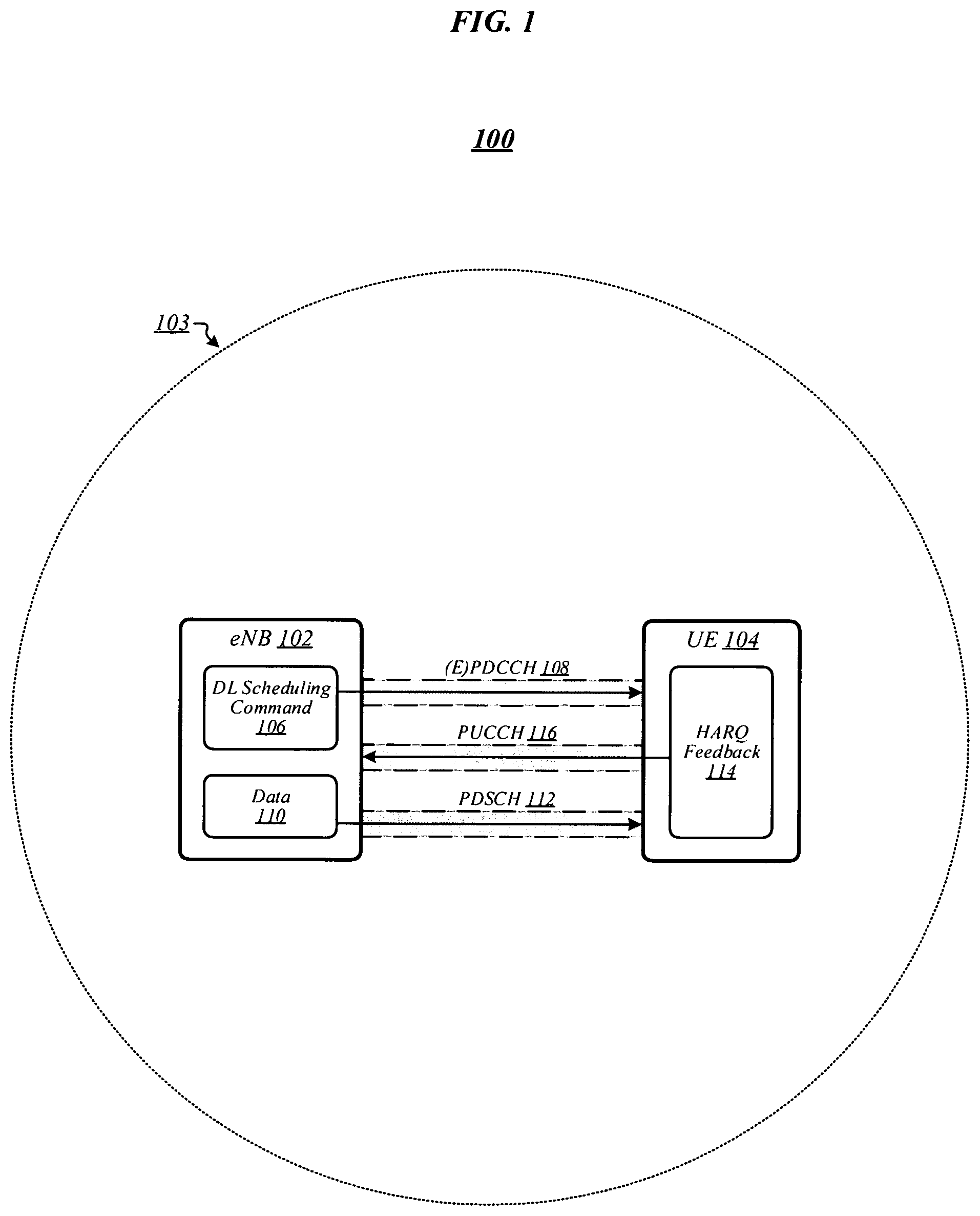
[0021] FIG. 1 illustrates an example of an operating environment 100 that may be representative of various embodiments. In operating environment 100, an evolved node B (eNB) 102 generally serves a cell 103, and may provide user equipment (UE) 104 with wireless connectivity via a wireless carrier of cell 103. During ongoing operation, eNB 102 may identify data 110 to be transmitted to UE 104. In some embodiments, eNB 102 may schedule transmission of data 110 for an upcoming subframe, which may be referred to as the "transmit subframe" for data 110. In various embodiments, in order to notify UE 104 of the upcoming transmission, eNB 102 may send a downlink (DL) scheduling command 106 to UE 104 over a physical downlink control channel (PDCCH) or enhanced physical downlink control channel (EPDCCH), collectively depicted in FIG. 1 as (E)PDCCH 108. In some embodiments, eNB 102 may then transmit data 110 to UE 104 over a physical downlink shared channel (PDSCH) 112 during the transmit subframe for data 110. In various embodiments, in response to receipt of DL scheduling command 106, UE 104 may identify the transmit subframe of data 110 and access one or more resources of PDSCH 112 during that transmit subframe to receive data 110.
[0022] In some embodiments, in order to confirm successful receipt of data 110--or to report non-receipt of some or all of data 110--UE 104 may generate HARQ feedback 114. In various embodiments, UE 104 may transmit HARQ feedback 114 to eNB 102 over a physical uplink control channel (PUCCH) 116. More particularly, in some embodiments, UE 104 may transmit HARQ feedback 114 to eNB 102 using a particular PUCCH resource of PUCCH 116 and according to a particular PUCCH format.
[0023] In various embodiments, UE 104 may be configured to use HARQ feedback 114 to provide feedback for one or more other DL data transmissions in addition to that of data 110. In some embodiments, UE 104 may be configured to use HARQ feedback 114 to provide feedback for one or more DL data transmissions occurring during a different subframe (or set of different subframes) than that during which the DL transmission of data 110 occurs. In various embodiments, UE 104 may be configured to use HARQ feedback 114 to provide feedback for one or more DL data transmissions performed using a different carrier (or set of different carriers) than that used for the DL transmission of data 110. In some embodiments, UE 104 may be configured to use HARQ feedback 114 to provide feedback for DL data transmissions of multiple subframes and multiple carriers. For example, in various embodiments, carrier aggregation may be used to enable DL data transmission to UE 104 via each of a set of aggregated component carriers, and UE 104 may be configured to use HARQ feedback 114 to provide feedback for DL transmissions collectively performed during multiple subframes using multiple such component carriers. In some such embodiments, cell 103 may comprise a primary cell (PCell) with respect to wireless communications with/by UE 104. The embodiments are not limited in this context.
[0024] In various embodiments, UE 104 may select the PUCCH format that it uses for transmission of HARQ feedback 114 based on the size of HARQ feedback 114, which in turn may depend on the amount of transmitted DL data for which feedback is being provided. For example, in some embodiments, UE 104 may use one of relatively compact PUCCH formats 1a or 1b if HARQ feedback 114 merely includes feedback for DL data transmission of a single subframe and single carrier, and may use the larger PUCCH format 3 if HARQ feedback 114 includes feedback for DL data transmissions of multiple subframes and/or multiple component carriers.
[0025] In various embodiments, an enhanced carrier aggregation scheme may be implemented to enable DL data transmission to UE 104 via any or all of a larger number of component carriers than are aggregated according to conventional techniques. For example, in some embodiments, an enhanced carrier aggregation scheme may be implemented to enable DL data transmission to UE 104 via up to 32 component carriers, rather than limiting such transmissions to a maximum of five component carriers in accordance with conventional LTE carrier aggregation protocols. In various such embodiments, conventional PUCCH formats may not be large enough to accommodate the potential amounts of HARQ feedback that may need to be transmitted at one time. For example, while PUCCH format 3 may be used to accommodate up to 21 bits of HARQ feedback, the provision of HARQ feedback for respective DL data transmissions over each of 32 component carriers may require 64 bits if cell 103 is a frequency division duplexing (FDD) cell, and potentially 128 bits or more if cell 103 is a time division duplexing (TDD) cell.
[0026] In some embodiments, in order to accommodate the larger amounts of HARQ feedback that may need to be conveyed in conjunction with such an enhanced carrier aggregation scheme, an enhanced PUCCH format may be implemented. For example, in various embodiments, an enhanced PUCCH format may be implemented that may be used to transmit up to 128 bits of HARQ feedback. However, if the enhanced PUCCH format is used for all transmissions of aggregated HARQ feedback, significant amounts of PUCCH resources may be wasted. For example, if an enhanced PUCCH format designed to accommodate a 128-bit HARQ feedback payload is used to transmit 10 bits of HARQ feedback, the majority of the resources consumed by the PUCCH transmission may be wasted. The embodiments are not limited to this example.
[0027] Disclosed herein are HARQ feedback configuration techniques for broadband wireless networks. According to some such techniques, an eNB such as eNB 102 may include HARQ feedback configuration information in a DL scheduling command in order to specify one or more HARQ feedback configuration parameters. In various embodiments, the one or more HARQ feedback configuration parameters may include a PUCCH format to be used for HARQ feedback transmission. In some embodiments, the one or more HARQ feedback configuration parameters may include a PUCCH resource to be used for HARQ feedback transmission. In various embodiments, the one or more HARQ feedback configuration parameters may include a HARQ feedback payload size. The embodiments are not limited in this context.
[0028] FIG. 2 illustrates an example of an operating environment 200 that may be representative of the implementation of one or more of the disclosed HARQ feedback configuration techniques according to some embodiments. In operating environment 200, eNB 102 may send a DL scheduling command 206 to UE 104 over (E)PDCCH 108 in order to notify UE 104 of an upcoming transmission of data 210 to UE 104 over PDSCH 112. In response to receipt of DL scheduling command 206, UE 104 may monitor the appropriate resource(s) of PDSCH 112 during the transmit subframe for data 210. UE 104 may then include HARQ feedback for data 210 in HARQ feedback 214 that it transmits over PUCCH 116 to eNB 102.
[0029] In various embodiments, in addition to feedback for data 210, HARQ feedback 214 may include feedback for one or more other DL data transmissions to UE 104. In some embodiments, HARQ feedback 214 may include respective feedback for DL data transmissions to UE 104 over each of multiple component carriers. In various embodiments, PDSCH 112 may comprise a PDSCH of one of a plurality of aggregated component carriers, and HARQ feedback 214 may include feedback for DL data transmissions to UE 104 over respective PDSCHs of one or more other component carriers comprised among the plurality of aggregated component carriers. In some embodiments, HARQ feedback 214 may include respective feedback for DL data transmissions to UE 104 during each of multiple subframes. In various embodiments, for example, during a given UL subframe, UE 104 may need to provide HARQ feedback for each of a set of multiple DL subframes, and HARQ feedback 214 may comprise the respective HARQ feedback for each such DL subframe. Hereinafter, the term "HARQ feedback bundling window" shall be employed to denote such a set of multiple DL subframes.
[0030] In some embodiments, DL scheduling command 206 may comprise HARQ feedback configuration information (HFCI) field 218. In various embodiments, HFCI field 218 may comprise a one-bit field. In some embodiments, HFCI field 218 may only be permitted to be present in DL scheduling commands that map onto UE-specific (E)PDCCH search spaces corresponding to the cell radio network temporary identifiers (C-RNTIs) to which they are addressed. In various embodiments, eNB 102 may construct DL scheduling command 206 according to a particular defined DL control information (DCI) format. In some embodiments, that DCI format may comprise an enhanced version of a conventional DCI format. In various embodiments, for example, enhanced versions of one or more of DCI formats 1, 1A, 1B, 1D, 2, 2A, 2B, 2C, and 2D may be defined that include HFCI field 218, and eNB 102 may construct DL scheduling command 206 in accordance with one such enhanced DCI format. The embodiments are not limited in this context.
[0031] In some embodiments, eNB 102 may use HFCI field 218 to indicate a PUCCH format that UE 104 should use in transmitting HARQ feedback 214 over PUCCH 116 to eNB 102. In various such embodiments, eNB 102 may select the value of HFCI field 218 based on the value-to-parameter correspondences illustrated in Table 1 below. In such embodiments, eNB 102 may set HFCI field 218 to `0` in order to indicate that UE 104 should use a first PUCCH format in transmitting HARQ feedback 214, or may set HFCI field 218 to `1` in order to indicate that UE 104 should use a second PUCCH format in transmitting HARQ feedback 214. In some embodiments, the first and second PUCCH formats may include a conventional PUCCH format and an enhanced PUCCH format designed to accommodate larger HARQ feedback payloads. For example, in various embodiments, eNB 102 may set the value of HFCI field 218 to `1` in order to indicate that such an enhanced PUCCH format is to be used, or may set the value of HFCI field 218 to `0` in order to indicate that PUCCH format 3 is to be used. In some other embodiments, both of the two PUCCH formats may comprised enhanced PUCCH formats. The embodiments are not limited in this context.
TABLE-US-00001 TABLE 1 Bit in Corresponding HARQ Feedback HFCI Field 218 Configuration Parameter `0` The 1.sup.st PUCCH format configured by the higher layers or fixed in specification `1` The 2.sup.nd PUCCH format configured by the higher layers or fixed in specification
[0032] In various embodiments, based on HFCI field 218, UE 104 may identify a PUCCH format according to which to transmit HARQ feedback 214 over PUCCH 116 to eNB 102. In some embodiments, based on the identified PUCCH format, UE 104 may identify a PUCCH resource to be used in transmitting HARQ feedback 214 over PUCCH 116 to eNB 102. In various embodiments, UE 104 may identify the PUCCH resource as one of four PUCCH resources associated with the PUCCH format according to higher-layer configuration. In some such embodiments, UE 104 may identify the PUCCH resource based on the value of a transmit power control (TPC) field comprised in a DL scheduling command--which may or may not be DL scheduling command 206--that is associated with a DL data transmission for which HARQ feedback 214 includes feedback and that contains a DL assignment index (DAI) value that is greater than 1. The embodiments are not limited in this context.
[0033] In various embodiments, after identifying the PUCCH format according to which HARQ feedback 214 is to be transmitted over PUCCH 116 to eNB 102, UE 104 may determine a HARQ payload size O.sup.ACK for HARQ feedback 214 based on the identified PUCCH format. In some embodiments, particular respective HARQ payload sizes for use in conjunction with the first and second PUCCH formats may be predefined, or may be configured by higher layer signaling. In various embodiments, for example, O.sup.ACK may be predefined or configured by higher layers to be equal to 21 when PUCCH format 3 is being used, and may be predefined or configured by higher layers to be equal to 64 or 128 when an enhanced PUCCH format designed to accommodate larger HARQ feedback payloads is being used. The embodiments are not limited to this example.
[0034] In some embodiments, once it determines O.sup.ACK, UE 104 may construct HARQ feedback 214 as a sequence of O.sup.ACK bits O.sub.0.sup.ACK, O.sub.1.sup.ACK, . . . , O.sub.O.sub.ACK-1.sup.ACK. In various embodiments, in generating HARQ feedback 214 for a plurality of DL data transmissions of a HARQ feedback bundling window, UE 104 may order the bits O.sub.0.sup.ACK, O.sub.1.sup.ACK, . . . , O.sub.O.sub.ACK-1.sup.ACK according to the values of DAI fields comprised in the DL scheduling commands corresponding to those DL data transmissions. In some embodiments, the HARQ feedback for a PDSCH transmission with a corresponding PDCCH/EPDCCH transmission or for a PDCCH/EPDCCH indicating downlink semi-persistent scheduling (SPS) release in a subframe n-k may be associated with O.sub.DAI(k)-1.sup.ACK if a configured transmission mode supports one transport block or spatial HARQ feedback bundling is applied, and otherwise may be associated with O.sub.2DAI(k)-2.sup.ACK and O.sub.2DAI(k)-1.sup.ACK, where DAI(k) represents the value of the DAI field in a detected DL scheduling command of DCI format 1, 1A, 1B, 1D, 2, 2A, 2B, 2C, or 2D detected in the HARQ feedback bundling window, and O.sub.2DAI(k)-2.sup.ACK and O.sub.2DAI(k)-1.sup.ACK represent HARQ feedback for codewords 0 and 1, respectively. In various embodiments in which N.sub.SPS>0, HARQ feedback for a PDSCH transmission for which there is no corresponding PDCCH/EPDCCH transmission may be mapped to O.sub.O.sub.ACK-1.sup.ACK. In some embodiments, HARQ feedback bits that correspond to PDCCH/EPDCCH transmissions without any detected corresponding PDSCH transmissions or correspond to non-detected PDCCH/EPDCCH downlink SPS release indications may be set to NACK. The embodiments are not limited in this context.
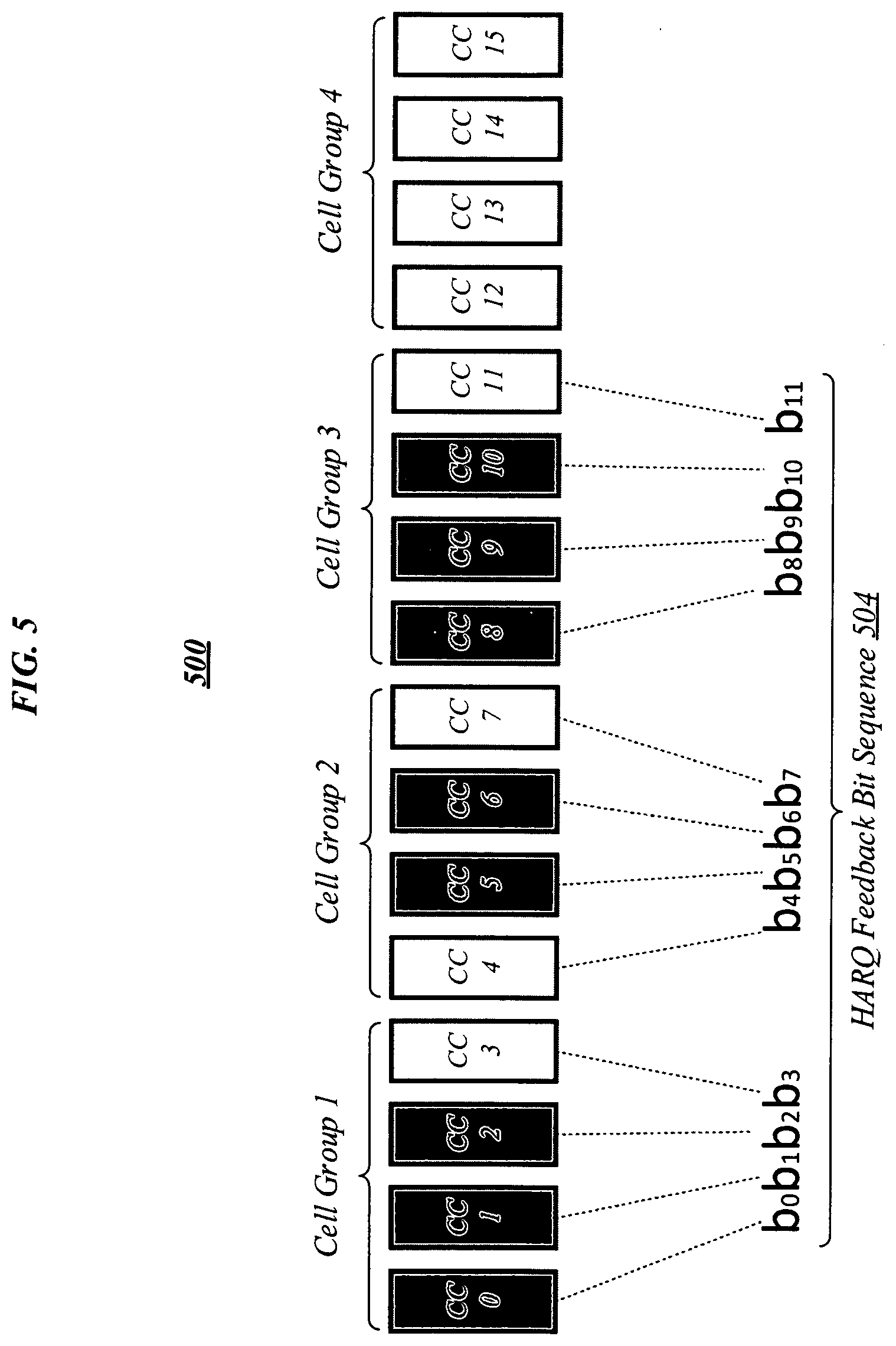
[0035] FIG. 3 illustrates an example of a HARQ feedback generation process 300 that may be representative of the implementation of one or more of the disclosed HARQ feedback configuration techniques according to various embodiments. For example, HARQ feedback generation process 300 may be representative of a HARQ feedback generation process that UE 104 may use to generate HARQ feedback 214 following a determination that HARQ feedback 214 is to be transmitted using PUCCH format 3 and a determination that HARQ feedback 214 is to comprise 21 bits. According to HARQ feedback generation process 300, for a UE configured with an aggregated set of ten component carriers--each corresponding to a respective one of cells 0 to 9--a HARQ feedback bit sequence 304 may be generated for a HARQ feedback bundling window 302. In this example, HARQ feedback bundling window 302 comprises a series of four subframes: subframe n, subframe n+1, subframe n+2, and subframe n+3. The embodiments are not limited to this example.
[0036] According to HARQ feedback generation process 300, construction of HARQ feedback bit sequence 304 proceeds on a subframe-by-subframe basis, and within each subframe, on a cell-by-cell basis. For each subframe, any cells for which previously received DL scheduling commands had indicated scheduled DL data transmissions may be identified, and for each such cell, a respective HARQ feedback bit may be generated to indicate whether the scheduled DL data transmission was successfully received. For example, cells 0, 2, 5, and 8 may be identified as cells from which DL data transmissions were expected during subframe n, and HARQ feedback bits b.sub.0, b.sub.1, b.sub.2, and b.sub.3 may be generated to indicate whether the scheduled DL data transmissions were successfully received from respective cells 0, 2, 5, and 8 during subframe n.
[0037] In order to account for the possibility of some DL scheduling commands pertaining to HARQ feedback bundling window 302 having been missed, DAI values comprised in received DL scheduling commands pertaining to HARQ feedback bundling window 302 may be analyzed. According to HARQ feedback generation process 300, when discontinuities are detected in such DAI values, HARQ feedback bits may be generated for DL data transmissions of which the UE had been unaware. In the example depicted in FIG. 3, DL scheduling commands corresponding to DL data transmissions of cells 2 and 3 during subframe n+1 may have been missed. However, based on respective DAI values of 5 and 8 comprised in DL scheduling commands corresponding to DL data transmissions of cells 0 and 8 during subframe n+1, it may be concluded that DL scheduling commands were missed for DL data transmissions of two of cells 1 to 7 during subframe n+1. Thus, HARQ feedback bits b.sub.4, b.sub.5, b.sub.6, and b.sub.7 may be generated for subframe n+1. Bits b.sub.4 and b.sub.7 may be set to indicate whether DL data transmissions were successfully received from respective cells 0 and 8 during subframe n+1, and bits b.sub.5 and b.sub.6 may be set to NACKs.
[0038] Similarly, for subframe n+2, HARQ feedback bits b.sub.8, b.sub.9, and b.sub.10 may be generated. Bits b.sub.8 and b.sub.10 may be set to indicate whether DL data transmissions were successfully received from respective cells 2 and 6 during subframe n+2, and bit b.sub.9 may be set to a NACK based on detection of a missed DL scheduling command, which in this example was a DL scheduling command for a DL data transmission of cell 4. For subframe n+3, a HARQ feedback bit b.sub.11 may be generated and set to indicate whether a DL data transmission was successfully received from cell 7 during subframe n+3. Following the generation of HARQ feedback bits b.sub.0 to b.sub.11, in accordance with a determination that HARQ feedback bit sequence 304 is to comprise 21 bits, nine additional bits b.sub.12 to b.sub.20 may be generated and set to NACKs. Finally, HARQ feedback bit sequence 304 may be generated by concatenating HARQ feedback bits b.sub.0 to b.sub.20 to obtain a bit sequence of 21 bits. The embodiments are not limited to this example.
[0039] FIG. 4 illustrates an example of an operating environment 400 that may be representative of some embodiments. In operating environment 400, as in operating environment 200 of FIG. 2, UE 104 may receive DL scheduling command 206 and generate HARQ feedback 214. However, in operating environment 400, DL scheduling command 206 may comprise a multi-bit HFCI field 418. In various embodiments, eNB 102 may use multi-bit HFCI field 418 to specify multiple HARQ feedback configuration parameters In some embodiments, HFCI field 418 may only be permitted to be present in DL scheduling commands that map onto UE-specific (E)PDCCH search spaces corresponding to the cell radio network temporary identifiers (C-RNTIs) to which they are addressed. In various embodiments, enhanced versions of one or more of DCI formats 1, 1A, 1B, 1D, 2, 2A, 2B, 2C, and 2D may be defined that include multi-bit HFCI field 418, and eNB 102 may construct DL scheduling command 206 in accordance with one such enhanced DCI format. The embodiments are not limited in this context.
[0040] Table 2 illustrates a first example of a value-to-parameter mapping that may be defined in some embodiments for a two-bit HFCI field 418. According to the value-to-parameter mapping illustrated in Table 2, eNB 102 may use HFCI field 418 to indicate both a PUCCH format and a PUCCH resource that UE 104 should use in transmitting HARQ feedback 214 over PUCCH 116 to eNB 102. Namely, eNB 102 may set HFCI field 418 to `00` to indicate a first PUCCH format and a first PUCCH resource, may set HFCI field 418 to `01` to indicate the first PUCCH format and a second PUCCH resource, may set HFCI field 418 to `10` to indicate a second PUCCH format and the first PUCCH resource, or may set HFCI field 418 to `11` to indicate the second PUCCH format and the second PUCCH resource.
TABLE-US-00002 TABLE 2 Bits in Corresponding HARQ Feedback HFCI Field 418 Configuration Parameters `00` The 1.sup.st PUCCH format with the 1st PUCCH resource value configured by the higher layers `01` The 1.sup.st PUCCH format with 2.sup.nd PUCCH resource value configured by the higher layers `10` The 2.sup.nd PUCCH format with the 1.sup.st PUCCH resource value configured by the higher layers `11` The 2.sup.nd PUCCH format with the 2.sup.nd PUCCH resource value configured by the higher layers
[0041] Table 3 illustrates a second example of a value-to-parameter mapping that may be defined in various embodiments for a two-bit HFCI field 418. Like the mapping illustrated in Table 2, the mapping illustrated in Table 3 may enable eNB 102 to use HFCI field 418 to indicate both a PUCCH format and a PUCCH resource that UE 104 should use in transmitting HARQ feedback 214 over PUCCH 116 to eNB 102. However, the value-to-parameter mapping illustrated in Table 3 may enable eNB 102 to select a PUCCH resource for use with PUCCH format 2 from among three candidate values rather than two. According to the value-to-parameter mapping illustrated in Table 3, eNB 102 may set HFCI field 418 to `00` to indicate a first PUCCH format and a first PUCCH resource, may set HFCI field 418 to `01` to indicate a second PUCCH format and the first PUCCH resource, may set HFCI field 418 to `10` to indicate the second PUCCH format and a second PUCCH resource, or may set HFCI field 418 to `11` to indicate the second PUCCH format and a third PUCCH resource.
TABLE-US-00003 TABLE 3 Bits in Corresponding HARQ Feedback HFCI Field 418 Configuration Parameters `00` The 1.sup.st PUCCH format with the 1st PUCCH resource value configured by the higher layers `01` The 2.sup.nd PUCCH format with the 1.sup.st PUCCH resource value configured by the higher layers `10` The 2.sup.nd PUCCH format with the 2.sup.nd PUCCH resource value configured by the higher layers `11` The 2.sup.nd PUCCH format with the 3.sup.rd PUCCH resource value configured by the higher layers
[0042] In some embodiments, respective corresponding HARQ feedback payload sizes may be predefined or configured by higher-layer signaling for the first and second PUCCH formats in conjunction with the use of a two-bit HFCI field 418 according to the value-to-parameter mapping of Table 2 or Table 3. In various embodiments, for example, a 21-bit HARQ feedback payload size may be predefined for the first PUCCH format and a 128-bit HARQ feedback payload size may be predefined for the second PUCCH format. In some embodiments, the first PUCCH format may comprise PUCCH format 3 and the second PUCCH format may comprise an enhanced PUCCH format designed to accommodate larger HARQ feedback payloads. In various embodiments, the second PUCCH format may comprise a physical uplink shared channel (PUSCH)-based PUCCH format. The embodiments are not limited in this context.
[0043] Table 4 illustrates a third example of a value-to-parameter mapping that may be defined in some embodiments for a two-bit HFCI field 418. According to the value-to-parameter mapping illustrated in Table 4, eNB 102 may use HFCI field 418 to indicate a PUCCH format and either a PUCCH resource or a HARQ feedback payload size. Namely, eNB 102 may set HFCI field 418 to `00` to indicate a first PUCCH format and a first PUCCH resource, may set HFCI field 418 to `01` to indicate the first PUCCH format and a second PUCCH resource, may set HFCI field 418 to `10` to indicate a second PUCCH format and a first HARQ feedback payload size, and may set HFCI field 418 to `11` to indicate the second PUCCH format and a second HARQ feedback payload size.
TABLE-US-00004 TABLE 4 Bits in Corresponding HARQ Feedback HFCI Field 418 Configuration Parameters `00` The 1.sup.st PUCCH format with the 1st PUCCH resource value configured by the higher layers `01` The 1.sup.st PUCCH format with 2.sup.nd PUCCH resource value configured by the higher layers `10` The 2.sup.nd PUCCH format with the 1.sup.st HARQ-ACK codebook size `11` The 2.sup.nd PUCCH format with the 2.sup.nd HARQ-ACK codebook size
[0044] In various embodiments, the first PUCCH format corresponding to respective HFCI field 418 values of `00` and `01` according to the value-to-parameter mapping of Table 4 may comprise PUCCH format 3. In some embodiments, the second PUCCH format corresponding to respective HFCI field 418 values of `10` and `11` according to the value-to-parameter mapping of Table 4 may comprise an enhanced PUCCH format designed to accommodate larger HARQ feedback payloads. In various such embodiments, the first and second HARQ feedback payload sizes corresponding to respective HFCI field 418 values of `10` and `11` according to the value-Jo to-parameter mapping of Table 4 may both be comprised among a set of HARQ feedback payload sizes designated for use in conjunction with the enhanced PUCCH format. In some embodiments, for example, the first and second HARQ feedback payload size may comprise two different numbers of bits comprised among the set {32 bits, 64 bits, 128 bits}. In various embodiments, HARQ feedback payload sizes to which HFCI field 418 values of `10` and `11` may be used to refer may be defined to differ between TDD environments and FDD environments. In an example embodiment, in the context of a TDD PUCCH, HFCI field 418 values of `10` and `11` may indicate 64-bit and 128-bit HARQ feedback payload sizes, respectively. In the same example embodiment, in the context of an FDD PUCCH, HFCI field 418 values of `10` and `11` may indicate 32-bit and 64-bit HARQ feedback payload sizes, respectively. The embodiments are not limited to this example.
[0045] Table 5 illustrates a fourth example of a value-to-parameter mapping that may be defined in some embodiments for a two-bit HFCI field 418. Like the mapping illustrated in Table 4, the mapping illustrated in Table 5 may enable eNB 102 to use HFCI field 418 to indicate a PUCCH format and either a PUCCH resource or a HARQ feedback payload size. However, the value-to-parameter mapping illustrated in Table 5 may enable eNB 102 to select a HARQ feedback payload size for use with PUCCH format 2 from among three candidate sizes rather than two. According to the mapping illustrated in Table 5, eNB 102 may set HFCI field 418 to `00` to indicate a first PUCCH format and a first PUCCH resource, may set HFCI field 418 to `01` to indicate a second PUCCH format and a first HARQ feedback payload size, may set HFCI field 418 to `10` to indicate the second PUCCH format and a second HARQ feedback payload size, and may set HFCI field 418 to `11` to indicate the second PUCCH format and a third HARQ feedback payload size.
TABLE-US-00005 TABLE 5 Bits in Corresponding HARQ Feedback HFCI Field 418 Configuration Parameters `00` The 1.sup.st PUCCH format with the 1st PUCCH resource value configured by the higher layers `01` The 2.sup.nd PUCCH format with the 1.sup.st HARQ-ACK codebook size `10` The 2.sup.nd PUCCH format with the 2.sup.nd HARQ-ACK codebook size `11` The 2.sup.nd PUCCH format with the 3.sup.rd HARQ-ACK codebook size
[0046] In various embodiments, in conjunction with the use of a two-bit HFCI field 418 according to the value-to-parameter mapping of Table 4 or Table 5, a particular HARQ feedback payload size to be used in combination with the first PUCCH format may be predefined or configured by higher-layer signaling. For example, in some embodiments, a HARQ feedback payload size of 21 bits may be predefined or configured by higher-layer signaling for use with the first PUCCH format, which may comprise PUCCH format 3. In various embodiments, in conjunction with the use of a two-bit HFCI field 418 according to the value-to-parameter mapping of Table 4 or Table 5, a particular PUCCH resource to be used in combination with the second PUCCH format may be predefined or configured by higher-layer signaling. The embodiments are not limited in this context.
[0047] Table 6 illustrates a fifth example of a value-to-parameter mapping that may be defined in some embodiments for a two-bit HFCI field 418. According to the value-to-parameter mapping illustrated in Table 6, eNB 102 may use HFCI field 418 to indicate a PUCCH format and one or both of a PUCCH resource and a HARQ feedback payload size. Namely, eNB 102 may set HFCI field 418 to `00` to indicate a first PUCCH format and a first PUCCH resource, may set HFCI field 418 to `01` to indicate a second PUCCH format, the first PUCCH resource, and a first HARQ feedback payload size, may set HFCI field 418 to `10` to indicate the second PUCCH format, a second PUCCH resource, and the first HARQ feedback payload size, or may set HFCI field 418 to `11` to indicate the second PUCCH format and a second HARQ feedback payload size.
TABLE-US-00006 TABLE 6 Bits in Corresponding HARQ Feedback HFCI Field 418 Configuration Parameters `00` The 1.sup.st PUCCH format with the 1st PUCCH resource value configured by the higher layers `01` The 2.sup.nd PUCCH format with the 1.sup.st HARQ-ACK codebook size, 1.sup.st PUCCH resource value configured by the higher layers `10` The 2.sup.nd PUCCH format with the 1.sup.st HARQ-ACK codebook size, 2.sup.nd PUCCH resource value configured by the higher layers `11` The 2.sup.nd PUCCH format with the 2.sup.nd HARQ-ACK codebook size
[0048] In various embodiments, in conjunction with the use of a two-bit HFCI field 418 according to the value-to-parameter mapping of Table 6, a particular HARQ feedback payload size to be used in combination with the first PUCCH format and the first PUCCH resource may be predefined or configured by higher-layer signaling. In some embodiments, in conjunction with the use of a two-bit HFCI field 418 according to the value-to-parameter mapping of Table 6, a particular PUCCH resource to be used in combination with the second PUCCH format and the second HARQ feedback payload size may be predefined or configured by higher-layer signaling. The embodiments are not limited in this context.
[0049] Table 7 illustrates a sixth example of a value-to-parameter mapping that may be defined in various embodiments for a two-bit HFCI field 418. According to the value-to-parameter mapping illustrated in Table 7, eNB 102 may use HFCI field 418 to indicate a PUCCH format and a PUCCH resource, and possibly a HARQ feedback payload size as well. Namely, eNB 102 may set HFCI field 418 to `00` to indicate a first PUCCH format and a first PUCCH resource, may set HFCI field 418 to `01` to indicate a second PUCCH format, the first PUCCH resource, and a first HARQ feedback payload size, may set HFCI field 418 to `10` to indicate the second PUCCH format, a second PUCCH resource, and a second HARQ feedback payload size, or may set HFCI field 418 to `11` to indicate the second PUCCH format, a third PUCCH resource, and a third HARQ feedback payload size. In some embodiments, in conjunction with the use of a two-bit HFCI field 418 according to the value-to-parameter mapping of Table 7, a particular HARQ feedback payload size to be used in combination with the first PUCCH format and the first PUCCH resource may be predefined or configured by higher-layer signaling. The embodiments are not limited in this context.
TABLE-US-00007 TABLE 7 Bits in Corresponding HARQ Feedback HFCI Field 418 Configuration Parameters `00` The 1.sup.st PUCCH format with the 1st PUCCH resource value configured by the higher layers `01` The 2.sup.nd PUCCH format with the 1.sup.st HARQ-ACK codebook size, 1.sup.st PUCCH resource value configured by the higher layers `10` The 2.sup.nd PUCCH format with the 2.sup.nd HARQ-ACK codebook size, 2.sup.nd PUCCH resource value configured by the higher layers `11` The 2.sup.nd PUCCH format with the 3.sup.rd HARQ-ACK codebook size, 3.sup.rd PUCCH resource value configured by higher layers.
[0050] It is to be appreciated that although Tables 2 to 7 illustrate various examples of value-to-parameter mappings that may be defined for an HFCI field 418 comprising two bits, an HFCI field 418 comprising more than two bits may be implemented in various embodiments. Table 8 illustrates an example of a value-to-parameter mapping that may be defined in some embodiments for an X-bit HFCI field 418, where X>2.
TABLE-US-00008 TABLE 8 Decimal Value of Bit String in X-Bit HFCI Field 418 W 0 1 1 2 2 3 . . . . . . 2.sup.x - 1 .sup. 2.sup.x
[0051] According to the value-to-parameter mapping illustrated in Table 8, eNB 102 may use an X-bit HFCI field 418 to indicate a value of a parameter W. More particularly, in this example, eNB 102 may use the X-bit HFCI field 418 to identify an integer in the inclusive range [1, 2.sup.X] as the value of W. In various embodiments, following receipt of DL scheduling command 206, UE 104 may identify the value of W based on the contents of HFCI field 418 and may then identify--based on the value of W--a HARQ feedback payload size to be used in transmitting HARQ feedback 214 over PUCCH 116 to eNB 102. In some such embodiments, UE 104 may use W to identify such a HARQ feedback payload size O.sup.ACK according to Equation (1) as follows:
O.sup.ACK=W+2.sup.X.left brkt-top.(U-W)/2.sup.X.right brkt-bot. (1)
where U denotes a total number of PDSCH transmissions and PDCCH downlink SPS release indications received during a HARQ feedback bundling window. In various embodiments, based on an O.sup.ACK value determined in such fashion, UE 104 may determine one or both of a PUCCH format and a PUCCH resource for use in transmitting HARQ feedback 214 over PUCCH 116 to eNB 102. In some embodiments, for example, UE 104 may transmit HARQ feedback 214 using a first PUCCH format and a corresponding first PUCCH resource if O.sup.ACK.ltoreq.21, and may transmit HARQ feedback 214 using a second PUCCH format and a corresponding second PUCCH resource if O.sup.ACK>21. In various such embodiments, the first PUCCH format may comprise PUCCH format 3, and the second PUCCH format may comprise an enhanced PUCCH format designed to accommodate larger HARQ feedback payloads. The embodiments are not limited in this context.
[0052] Table 9 illustrates a more generalized form of a value-to-parameter mapping that may be defined in some embodiments for X-bit HFCI field 418. According to the value-to-parameter mapping illustrated in Table 9, each of 2.sup.X-1 possible values of d--where d represents a decimal value of a bit string of X bits contained in HFCI field 418--is defined to indicate a particular respective set of HARQ feedback configuration parameters {F.sub.d, O.sup.ACK.sup.d, R.sub.d}. For any given value of d, F.sub.d may comprise a PUCCH format indicated by that value of d, O.sup.ACK.sup.d may comprise a HARQ feedback payload size indicated by that value of d, and R.sub.d may comprise a PUCCH resource indicated by that value of d.
TABLE-US-00009 TABLE 9 Decimal Value d of Bit String in X-Bit PUCCH HARQ Feedback PUCCH HFCI Field 418 Format Payload Size Resource 0 F.sub.0 O.sup.ACK.sup.0 R.sub.0 1 F.sub.1 O.sup.ACK.sup.1 R.sub.1 . . . . . . . . . . . . 2.sup.x - 1 F.sub.2.sub.x.sub.-1 O.sup.ACK.sub.2.sub.x.sub.-1 R.sub.2.sub.x.sub.-1
[0053] It is to be appreciated that in various embodiments, some or all of these three parameters may be the same for multiple given values of d. Table 10 illustrates an example of such an embodiment. In the example illustrated in Table 10, HFCI field 418 comprises 3 bits, and thus X is equal to three. F.sub.0 and F.sub.1 both correspond to PUCCH format 3, while F.sub.2 to F.sub.7 all correspond to an enhanced PUCCH format designed to accommodate larger HARQ feedback payloads. O.sup.ACK.sup.0 and O.sup.ACK.sup.1 both correspond to a 21-bit HARQ feedback payload size, O.sup.ACK.sup.2, O.sup.ACK.sup.3 and O.sup.ACK.sup.4 each correspond to a 64-bit HARQ feedback payload size, and O.sup.ACK.sup.5, O.sup.ACK.sup.6, and O.sup.ACK.sup.7 each correspond to a 128-bit HARQ feedback payload size. R.sub.0, R.sub.2, and R.sub.5 each correspond to a first PUCCH resource, R.sub.1, R.sub.3, and R.sub.6 each correspond to a second PUCCH resource, and R.sub.4 and R.sub.7 both correspond to a third PUCCH resource. The embodiments are not limited to this example.
TABLE-US-00010 TABLE 10 Bits in HFCI Field 418 d PUCCH Format H.F.P. Size PUCCH Resource `000` 0 F.sub.0 (PUCCH format 3) O.sup.ACK.sup.0 (21 bits) R.sub.0 (1.sup.st PUCCH resource) `001` 1 F.sub.1 (PUCCH format 3) O.sup.ACK.sup.1 (21 bits) R.sub.1 (2.sup.nd PUCCH resource) `010` 2 F.sub.2 (Enh. PUCCH format) O.sup.ACK.sup.2 (64 bits) R.sub.2 (1.sup.st PUCCH resource) `011` 3 F.sub.3 (Enh. PUCCH format) O.sup.ACK.sup.3 (64 bits) R.sub.3 (2.sup.nd PUCCH resource) `100` 4 F.sub.4 (Enh. PUCCH format) O.sup.ACK.sup.4 (64 bits) R.sub.4 (3.sup.rd PUCCH resource) `101` 5 F.sub.5 (Enh. PUCCH format) O.sup.ACK.sup.5 (128 bits) R.sub.5 (1.sup.st PUCCH resource) `110` 6 F.sub.6 (Enh. PUCCH format) O.sup.ACK.sup.6 (128 bits) R.sub.6 (2.sup.nd PUCCH resource) `111` 7 F.sub.7 (Enh. PUCCH format) O.sup.ACK.sup.7 (128 bits) R.sub.7 (3.sup.rd PUCCH resource)
[0054] In some embodiments, a conventional field within DL scheduling command 206 may be repurposed for use as HFCI field 418. In various embodiments, for example a 2-bit TPC field in DL scheduling command 206 may be used as a 2-bit HFCI field 418. In some such embodiments, such repurposing of TPC fields as 2-bit HFCI fields may be limited to TPC fields comprised in PDCCH assignments with DAI values greater than `1` or DAI values equal to `1` that are not the first PDCCH transmissions on the primary cell and TPC fields comprised in DCI of the corresponding PDCCH detected on the secondary cell. The embodiments are not limited in this context.
[0055] In various embodiments, rather than being repurposed for use as HFCI field 418, a conventional field within DL scheduling command 206 may be repurposed for use in combination with HFCI field 418 in conjunction with the indication of one or more HARQ feedback configuration parameters. For example, in some embodiments, the collective set of bits comprised in HFCI field 418 and a TPC field may indicate one or more of a PUCCH format, a PUCCH resource, and a HARQ feedback payload size. In various embodiments, the repurposed field may be used to independently specify one or more HARQ feedback configuration parameters. For example, in some embodiments, the TPC field may be used to indicate a PUCCH format, and HFCI field 418 may be used to indicate a PUCCH resource and a HARQ feedback payload size. In various other embodiments, HFCI field 418 and the repurposed field may be used to provide bits to be combined to obtain a bit string that maps to a particular set of HARQ feedback configuration parameters. For example, in some embodiments, UE 104 may obtain a bit string by concatenation the bits in HFCI field 418 with the bits in the TPC field, and may determine a set of HARQ feedback configuration parameters according to a value-to-parameter mapping of the general form illustrated in Table 9. The embodiments are not limited in this context.
[0056] In various embodiments, UE 104 may generate HARQ feedback 214 according to a HARQ feedback generation process that implements a cell-group-based approach to HARQ feedback payload size adaptation. In some embodiments, according to such an approach, the various configured DL component carriers may be divided into multiple HARQ feedback cell groups (CGs). In various such embodiments, the number of CGs may be an integer power of 2 and/or each CG may comprise a same number of component carriers. In some embodiments, each CG may be assigned a unique CG identifier (ID). In various embodiments, HFCI field 418 may comprise a bitmap that includes, for each of the multiple CGs, a respective bit that indicates whether a PDSCH transmission or SPS release is scheduled on at least one DL component carrier of that CG during the HARQ feedback bundling window. In some embodiments, UE 104 may determine a HARQ feedback payload size based on such a bitmap comprised in HFCI field 418.
[0057] In various embodiments, for each CG for which a PDSCH transmission or SPS release is scheduled on at least one DL component carrier during the HARQ feedback bundling window, UE 104 may generate a pre-defined number of HARQ feedback bits. In some embodiments, if the component carriers correspond to FDD cells, UE 104 may a number of HARQ feedback bits equal to the number of component carriers comprised in the CG. In various embodiments, if the component carriers correspond to TDD cells, UE 104 may generate a number of HARQ feedback bits equal to the total number of subframes comprised within the HARQ feedback bundling window. In some embodiments, UE 104 may refrain from generating HARQ feedback bits for any CG with respect to which neither a PDSCH transmission nor an SPS release is scheduled on any component carrier during the HARQ feedback bundling window.
[0058] FIG. 5 illustrates an example of a HARQ feedback generation process 500 that may be representative of a CG-based HARQ feedback generation process. In various embodiments, UE 104 may perform the HARQ feedback generation process illustrated in FIG. 5 in response to receipt of a DL scheduling command 206 in which HFCI field 418 contains the bitmap `1110`. In some embodiments, based on such a bitmap, UE 104 may determine that HARQ feedback bits are to be generated for CGs 1, 2, and 3, but not for CG 4. Each of CGs 1, 2, 3, and 4 comprises four respective component carriers. In this example, these various component carriers may correspond to FDD cells, and thus UE 104 may generate four respective HARQ feedback bits for each of CGs 1, 2, and 3, and assemble those various HARQ feedback bits into a 12-bit HARQ feedback bit sequence 504. In various embodiments, UE 104 may select a PUCCH format for use in transmission of HARQ feedback 214 based on the size of HARQ feedback bit sequence 504. In some embodiments, if the DAI field exists, the HARQ feedback payload can be further compressed according to the value of the DAI field with respect to each CG for which HARQ feedback bits are generated. The embodiments are not limited in this context.
[0059] In various embodiments, in conjunction with any of the various aforementioned approaches, UE 104 may be configured to autonomously select and use PUCCH format 1a/1b and a corresponding PUCCH resource to transmit HARQ feedback 214 under certain circumstances. In some embodiments, for example, UE 104 may be configured to autonomously select and use PUCCH format 1a/1b and a corresponding PUCCH resource when received DCI indicates only a PDSCH transmission or SPS release in the primary cell during the HARQ-ACK bundling window. In various such embodiments, the corresponding PUCCH resource may be Jo determined according to the lowest control channel element (CCE) index used to construct the PDCCH. In some embodiments, UE 104 may be configured to autonomously select and use PUCCH format 1a/1b and a corresponding PUCCH resource to transmit HARQ feedback for a primary cell PDSCH transmission during a subframe of the HARQ feedback bundling window for which no corresponding PDCCH/EPDCCH transmission is detected within that subframe. In various such embodiments, UE 104 may select the corresponding PUCCH resource from among four PUCCH resource values configured by higher layers, based on the value comprised in a TPC command for PUCCH field in DCI used to indicate a semi-persistent DL scheduling activation. The embodiments are not limited in this context.
[0060] Operations for the above embodiments may be further described with reference to the following figures and accompanying examples. Some of the figures may include a logic flow. Although such figures presented herein may include a particular logic flow, it can be appreciated that the logic flow merely provides an example of how the general functionality as described herein can be implemented. Further, the given logic flow does not necessarily have to be executed in the order presented unless otherwise indicated. In addition, the given logic flow may be implemented by a hardware element, a software element executed by a processor, or any combination thereof. The embodiments are not limited in this context.
[0061] FIG. 6 illustrates an example of a logic flow 600 that may be representative of the implementation of one or more of the disclosed HARQ feedback configuration techniques according to various embodiments. For
D00000
D00001
D00002
D00003
D00004
D00005
D00006
D00007
D00008
D00009
D00010
D00011
XML
uspto.report is an independent third-party trademark research tool that is not affiliated, endorsed, or sponsored by the United States Patent and Trademark Office (USPTO) or any other governmental organization. The information provided by uspto.report is based on publicly available data at the time of writing and is intended for informational purposes only.
While we strive to provide accurate and up-to-date information, we do not guarantee the accuracy, completeness, reliability, or suitability of the information displayed on this site. The use of this site is at your own risk. Any reliance you place on such information is therefore strictly at your own risk.
All official trademark data, including owner information, should be verified by visiting the official USPTO website at www.uspto.gov. This site is not intended to replace professional legal advice and should not be used as a substitute for consulting with a legal professional who is knowledgeable about trademark law.