Porous Interconnected Corrugated Carbon-based Network (iccn) Composite
El-Kady; Maher F. ; et al.
U.S. patent application number 16/791517 was filed with the patent office on 2020-06-25 for porous interconnected corrugated carbon-based network (iccn) composite. The applicant listed for this patent is The Regents of the University of California. Invention is credited to Maher F. El-Kady, Jee Youn Hwang, Richard B. Kaner.
| Application Number | 20200203086 16/791517 |
| Document ID | / |
| Family ID | 56010903 |
| Filed Date | 2020-06-25 |


View All Diagrams
| United States Patent Application | 20200203086 |
| Kind Code | A1 |
| El-Kady; Maher F. ; et al. | June 25, 2020 |
POROUS INTERCONNECTED CORRUGATED CARBON-BASED NETWORK (ICCN) COMPOSITE
Abstract
A porous interconnected corrugated carbon-based network (ICCN) composite and methods for making the same are disclosed. The porous ICCN composite is made up of a plurality of carbon layers that are interconnected and expanded apart from one another to form a plurality of pores. Metallic nanoparticles are disposed within the plurality of pores. In one embodiment, a light exposure only based method for producing the porous ICCN composite is disclosed. In another embodiment a light exposure plus an electrodeposition method for producing the porous ICCN composite is disclosed. In yet another exemplary embodiment, a capacitor having a first electrode and a second electrode separated from the first electrode by a dielectric wherein at least one of the first electrode and the second electrode is formed from the porous ICCN composite is disclosed.
| Inventors: | El-Kady; Maher F.; (Los Angeles, CA) ; Kaner; Richard B.; (Pacific Palisades, CA) ; Hwang; Jee Youn; (Seoul, KR) | ||||||||||
| Applicant: |
|
||||||||||
|---|---|---|---|---|---|---|---|---|---|---|---|
| Family ID: | 56010903 | ||||||||||
| Appl. No.: | 16/791517 | ||||||||||
| Filed: | February 14, 2020 |
Related U.S. Patent Documents
| Application Number | Filing Date | Patent Number | ||
|---|---|---|---|---|
| 14945232 | Nov 18, 2015 | 10650983 | ||
| 16791517 | ||||
| 62081237 | Nov 18, 2014 | |||
| Current U.S. Class: | 1/1 |
| Current CPC Class: | H01G 11/26 20130101; H01G 11/46 20130101; H01G 11/86 20130101; C01B 32/194 20170801; C25D 9/08 20130101; Y02E 60/13 20130101; Y02T 10/70 20130101; H01G 11/70 20130101; Y02T 10/7022 20130101; H01G 11/02 20130101; C01B 32/184 20170801; H01G 11/36 20130101 |
| International Class: | H01G 11/36 20060101 H01G011/36; H01G 11/86 20060101 H01G011/86; H01G 11/46 20060101 H01G011/46; H01G 11/26 20060101 H01G011/26; C25D 9/08 20060101 C25D009/08; C01B 32/184 20060101 C01B032/184; C01B 32/194 20060101 C01B032/194; H01G 11/70 20060101 H01G011/70; H01G 11/02 20060101 H01G011/02 |
Claims
1. A porous interconnected corrugated carbon-based network (ICCN) composite comprising: a plurality of carbon layers that are interconnected and expanded apart from one another to form a plurality of pores; and metallic nanoparticles disposed within the plurality of pores.
2. The porous ICCN composite of claim 1 wherein an average minor axis diameter of the plurality of pores ranges from about 2 nanometers to about 50 nanometers.
3. The porous ICCN composite of claim 1 wherein an average minor axis diameter of the plurality of pores ranges from about 50 nanometers to about 500 nanometers.
4. The porous ICCN composite of claim 1 wherein the metallic nanoparticles have a nanoflower shape.
5. The porous ICCN composite of claim 1 wherein the metallic nanoparticles are metal particles.
6. The porous ICCN composite of claim 1 wherein the metallic nanoparticles are metal oxide particles.
7. The porous ICCN composite of claim 6 wherein the metallic nanoparticles are particles of manganese dioxide (MnO.sub.2).
8. The porous ICCN composite of claim 6 wherein the metallic nanoparticles are particles of ruthenium dioxide (RuO.sub.2).
9. The porous ICCN composite of claim 6 wherein the metallic nanoparticles are particles of cobalt oxide (CO.sub.3O.sub.4).
10. The porous ICCN composite of claim 6 wherein the metallic nanoparticles are particles of nickel oxide (NiO).
11. The porous ICCN composite of claim 6 wherein the metallic nanoparticles are particles of iron oxide (Fe.sub.2O.sub.3).
12. The porous ICCN composite of claim 6 wherein the metallic nanoparticles are particles of copper oxide (CuO).
13. The porous ICCN composite of claim 6 wherein the metallic nanoparticles are particles of molybdenum trioxide (MoO.sub.3).
14. The porous ICCN composite of claim 6 wherein the metallic nanoparticles are particles of vanadium pentoxide (V.sub.2O.sub.5).
15. The porous ICCN composite of claim 6 wherein the metallic nanoparticles are particles of nickel hydroxide (Ni(OH).sub.2).
16. The porous ICCN composite of claim 1 wherein an electrical conductivity of the plurality of carbon layers is greater than about 0.1 siemens/meter.
17. The porous ICCN composite of claim 1 wherein the porous ICCN composite has an electrical conductivity that ranges from about 900 siemens/meter to about 1750 siemens/meter.
18. The porous ICCN composite of claim 1 wherein a total surface area per unit mass of the plurality of carbon layers is at least 1500 square meters per gram.
19. The porous ICCN composite of claim 1 wherein a percentage of surface area coverage of the metallic nanoparticles onto the plurality of carbon layers ranges from about 10% to about 95%.
20. The porous ICCN composite of claim 1 wherein the porous ICCN composite provides an energy density that ranges from about 2 Watt-hour/liter to about 41 Watt-hour/liter.
21. A method of producing porous ICCN composite comprising: providing a film comprising a mixture of a metallic precursor and a carbon-based oxide; and exposing at least a portion of the film to light to form a porous interconnected corrugated carbon-based network (ICCN) composite comprising: a plurality of carbon layers that are interconnected and expanded apart from one another to form a plurality of pores; and metallic nanoparticles disposed within the plurality of pores, wherein the light converts the metallic precursor to the metallic nanoparticles.
22. The method of producing porous ICCN composite of claim 21 wherein providing the film made of the mixture of the metallic precursor and the carbon-based oxide comprises: providing a solution comprising a liquid, the metallic precursor, and the carbon-based oxide; disposing the solution with the liquid, the metallic precursor, and the carbon-based oxide onto a substrate; and evaporating the liquid from the solution to form the film.
23. The method of producing the porous ICCN composite of claim 21 wherein the carbon-based oxide is graphite oxide.
24. The method of producing the porous ICCN composite of claim 21 wherein the metallic nanoparticles are particles of ruthenium oxide (RuO.sub.2).
25. The method of producing the porous ICCN composite of claim 21 wherein the metallic nanoparticles are particles of cobalt oxide (Co.sub.3O.sub.4).
26. The method of producing the porous ICCN composite of claim 21 wherein the metallic nanoparticles are particles of nickel oxide (NiO).
27. The method of producing the porous ICCN composite of claim 21 wherein the metallic nanoparticles are particles of vanadium pentoxide (V.sub.2O.sub.5).
28. The method of producing the porous ICCN composite of claim 21 wherein the metallic nanoparticles are particles of iron oxide (Fe.sub.2O.sub.3).
29. The method of producing the porous ICCN composite of claim 21 wherein the metallic nanoparticles are particles of copper oxide (CuO).
30. The method of producing the porous ICCN composite of claim 21 wherein the metallic nanoparticles are particles of molybdenum trioxide (MoO.sub.3).
31. The porous ICCN composite of claim 21 wherein an electrical conductivity of the plurality of carbon layers is greater than about 0.1 siemens/meter.
32. The porous ICCN composite of claim 21 wherein the porous ICCN composite has an electrical conductivity that ranges from about 900 siemens/meter to about 1750 siemens/meter.
33. A capacitor comprising: a first electrode; a dielectric; a second electrode separated from the first electrode by the dielectric wherein at least one of the first electrode and the second electrode is formed from a porous interconnected corrugated carbon-based network (ICCN) composite that comprises: a plurality of carbon layers that are interconnected and expanded apart from one another to form a plurality of pores; and metallic nanoparticles disposed within the plurality of pores.
34. The porous ICCN composite of claim 33 wherein an average minor axis diameter of the plurality of pores ranges from about 2 nanometers to about 550 nanometers.
35. The porous ICCN composite of claim 33 wherein an average minor axis diameter of the plurality of pores ranges from about 50 nanometers to about 500 nanometers.
36. The porous ICCN composite of claim 33 wherein the metallic nanoparticles have a nanoflower shape.
37. The porous ICCN composite of claim 33 wherein the metallic nanoparticles are metal particles.
38. The porous ICCN composite of claim 33 wherein the metallic nanoparticles are metal oxide particles.
39. The porous ICCN composite of claim 38 wherein the metallic nanoparticles are particles of manganese dioxide (MnO.sub.2).
40. The porous ICCN composite of claim 38 wherein the metallic nanoparticles are particles of ruthenium dioxide (RuO.sub.2).
41. The porous ICCN composite of claim 38 wherein the metallic nanoparticles are particles of cobalt oxide (CO.sub.3O.sub.4).
42. The porous ICCN composite of claim 38 wherein the metallic nanoparticles are particles of nickel oxide (NiO).
43. The porous ICCN composite of claim 38 wherein the metallic nanoparticles are particles of iron oxide (Fe.sub.2O.sub.3).
44. The porous ICCN composite of claim 38 wherein the metallic nanoparticles are particles of copper oxide (CuO).
45. The porous ICCN composite of claim 38 wherein the metallic nanoparticles are particles of molybdenum trioxide (MoO.sub.3).
46. The porous ICCN composite of claim 38 wherein the metallic nanoparticles are particles of vanadium pentoxide (V.sub.2O.sub.5).
47. The porous ICCN composite of claim 38 wherein the metallic nanoparticles are particles of nickel hydroxide (Ni(OH).sub.2).
48. The porous ICCN composite of claim 33 wherein an electrical conductivity of the plurality of carbon layers is greater than about 0.1 siemens/meter.
49. The porous ICCN composite of claim 33 wherein the porous ICCN composite has an electrical conductivity ranges from about 900 siemens/meter to about 1750 siemens/meter.
50. The porous ICCN composite of claim 33 wherein a total surface area per unit mass of the plurality of carbon layers ranges from about 1500 square meters per gram to about 1620 meters per gram.
51. The porous ICCN composite of claim 33 wherein a percentage of surface area coverage of the metallic nanoparticles onto the plurality of carbon layers ranges from about 10% to about 95%.
52. The porous ICCN composite of claim 33 wherein the porous ICCN composite provides an energy density that ranges from about 2 Watt-hour/liter to about 41 Watt-hour/liter.
53. The capacitor of claim 33 wherein the at least one of the first electrode and the second electrode provides a specific capacitance that ranges from about 400 Farads/gram to about 1400 Farads/gram.
54. The capacitor of claim 33 wherein the at least one of the first electrode and the second electrode provides an energy density that ranges from about 2 Watt-hour/liter to about 41 Watt-hour/liter.
55. The capacitor of claim 33 wherein the first electrode comprises a plurality of first extending electrode digits and the second electrode comprises a plurality of second extending electrode digits that are interdigitated with the first extending electrode digits.
56. The capacitor of claim 55 wherein the dielectric comprises graphite oxide (GO).
57. A method of producing porous interconnected corrugated carbon-based network (ICCN) composite comprising: forming a porous ICCN comprising a plurality of carbon layers that are interconnected and expanded apart from one another to form a plurality of pores; and electrodepositing metallic nanoparticles within the plurality of pores.
58. The method of producing the porous ICCN composite of claim 57 comprising providing a film made of a mixture of a metallic precursor and a carbon-based oxide that comprises: providing a solution comprising a liquid, the metallic precursor, and the carbon-based oxide; disposing the solution with the liquid, the metallic precursor, and the carbon-based oxide onto a substrate; and evaporating the liquid from the solution to form the film.
59. The method of producing the porous ICCN composite of claim 58 wherein the carbon-based oxide is graphite oxide.
60. The method of producing the porous ICCN composite of claim 58 wherein the metallic nanoparticles are particles of ruthenium oxide (RuO.sub.2).
61. The method of producing the porous ICCN composite of claim 58 wherein the metallic nanoparticles are particles of cobalt oxide (Co.sub.3O.sub.4).
62. The method of producing the porous ICCN composite of claim 58 wherein the metallic nanoparticles are particles of nickel oxide (NiO).
63. The method of producing the porous ICCN composite of claim 58 wherein the metallic nanoparticles are particles of vanadium pentoxide (V.sub.2O.sub.5).
64. The method of producing the porous ICCN composite of claim 58 wherein the metallic nanoparticles are particles of iron oxide (Fe.sub.2O.sub.3).
65. The method of producing the porous ICCN composite of claim 58 wherein the metallic nanoparticles are particles of copper oxide (CuO).
66. The method of producing the porous ICCN composite of claim 58 wherein the metallic nanoparticles are particles of molybdenum trioxide (MoO.sub.3).
67. The porous ICCN composite of claim 58 wherein an electrical conductivity of the plurality of carbon layers is greater than about 0.1 siemens/meter.
68. The porous ICCN composite of claim 58 wherein the porous ICCN composite has an electrical conductivity that ranges from about 900 siemens/meter to about 1750 siemens/meter.
69. The method of producing the porous ICCN composite of claim 57 wherein electrodepositing the metallic nanoparticles within the plurality of pores comprises: submerging the porous ICCN into an aqueous solution having a metallic precursor; and applying an electrical current through the porous ICCN to electrodeposit the metallic nanoparticles into the plurality of pores.
70. The method of producing the porous ICCN composite of claim 69 wherein the electrical current has a current density of at least 250 microamperes per square centimeter.
Description
RELATED APPLICATIONS
[0001] This application is a continuation of U.S. patent application Ser. No. 14/945,232, filed Nov. 18, 2015, which claims the benefit of U.S. provisional patent application No. 62/081,237, filed Nov. 18, 2014, the disclosures of which are incorporated herein by reference in their entireties.
FIELD OF THE DISCLOSURE
[0002] The present disclosure relates to a porous interconnected corrugated carbon-based network (ICCN) composite having increased energy density and increased power density.
BACKGROUND
[0003] Electrochemical capacitors offer significant advantages compared to conventional storage media, such as batteries and capacitors, provide significantly higher energy densities than conventional capacitors, and exhibit higher power and longer cycle life than batteries. Electrochemical capacitors can be separated into two general categories: electrical double layer capacitors (EDLCs) and pseudocapacitors. EDLCs store electrostatic charge at the interface between the electrode and electrolyte, where the charge accumulates on the electrode surface. The most important attributes of an EDLC electrode are high surface area and high porosity, as the amount of charge accumulation is related to exposed surface area.
[0004] Recent advances in carbon materials such as carbon nanotubes, two-dimensional one atom thick carbon sheets, and activated carbon (AC) have led to their use as the active material in EDLCs. Two-dimensional one atom thick carbon sheets are one of the most attractive materials for such applications, owing to their remarkably high surface area, excellent electrical and thermal conductivity, electrochemical stability, and mechanical properties. While carbon-based EDLCs can provide a theoretical capacitance up to 550 Farads per gram, this falls short for many practical applications, particularly when compared to electrochemical batteries. Pseudocapacitors, which are based on redox reactions of the electrode material, can have up to 10 times higher capacitance than EDLCs, yet their wide-spread applications have been limited due to lower power density and poor cycling stability.
[0005] In pseudocapacitors, only surface and near-surface sites can contribute to charge storage via redox reactions, where the electrode materials are commonly used metal oxides or conducting polymers. Among the metal oxides, ruthenium oxide (RuO.sub.2) has been widely studied as a material for pseudocapacitor applications due to its remarkably high specific capacitance (1300-2200 Farads per gram), highly reversible charge-discharge features, wide potential window, and high electrical conductivity (10.sup.5 siemens per centimeter). For practical applications of RuO.sub.2 as a pseudocapacitor electrode, power density and cycle life must be improved.
SUMMARY
[0006] A porous interconnected corrugated carbon-based network (ICCN) composite and methods for making the same are disclosed. The porous ICCN composite is made up of a plurality of carbon layers that are interconnected and expanded apart from one another to form a plurality of pores. Metallic nanoparticles are disposed within the plurality of pores.
[0007] The inventors have focused on developing a hybrid system in which the merits of EDLCs and pseudocapacitors are combined to overcome the shortcomings of each individual technology. Such hybrid electrochemical capacitors disclosed herein offer improved energy and power densities, as well as improved cycling stability. The inventors have identified that carbon-metal oxide nanocomposites with high electrical conductivities are of interest as electrodes for hybrid electrochemical capacitors with the proposition that they will benefit from the electrical conductivity of carbon and the high capacitance of metal oxides, thus providing systems with both higher energy density and higher power density.
[0008] The inventors have also identified a method for minimizing the number of steps in the preparation of an electrochemical capacitor, including, for example, limiting the necessary number of post-processing steps, and thereby maximizing the potential of these methods for practical scale-up application in industry.
[0009] Small-scale supercapacitors, referred to as microsupercapacitors, have emerged as promising energy sources for powering microelectronics. The inventors have identified applications of carbon-based/RuO.sub.2 electrodes in micro-supercapacitors that extend beyond the conventional parallel plate supercapacitors, for example, uses of carbon-based electrodes, such as carbon-based/RuO.sub.2 electrodes, in miniature interdigitated supercapacitor applications. This significant advancement avoids the difficulties characteristic of fabricating and processing hybrid materials into patterned microelectrodes.
[0010] Certain desirable features of the carbon materials that are useful for the applications described herein include high surface area, controlled porosity and ease of processing into electrodes. The combination of carbon with metal oxides results in hybrid electrodes with a higher specific capacitance compared to pure carbon electrodes, which has so far limited the energy density of supercapacitors currently available commercially. The subject matter described herein also provides for the preparation and processing of carbon/metal oxide electrodes into supercapacitors of different structures and configurations, especially for miniaturized electronics, in a manner that avoids many of the challenges that are incumbent upon traditional preparation and manufacturing processes. The inventors have identified, and herein describe, a composite material that is usable to construct electrodes for energy storage devices having increased energy density and increased power density and commercially scalable methods for producing the composite material.
[0011] In one aspect, described herein is a porous interconnected corrugated carbon-based network (ICCN) composite comprising: a plurality of carbon layers that are interconnected and expanded apart from one another to form a plurality of pores; and metallic nanoparticles disposed within the plurality of pores. In some embodiments, the porous ICCN has an average minor axis diameter of the plurality of pores that ranges from about 2 nanometers to about 550 nanometers. In some embodiments, the porous ICCN has an average minor axis diameter of the plurality of pores that ranges from about 10 nanometers to about 450 nanometers, or from about 25 nanometers to about 400 nanometers, or from about 50 nanometers to about 350 nanometers, or from about 75 nanometers to about 300 nanometers, or from about 100 nanometers to about 250 nanometers. In some embodiments, the range is from about 50 nanometers to about 500 nanometers.
[0012] In some embodiments, provided is a porous ICCN composite wherein the metallic nanoparticles have a nanoflower shape. In certain applications, the metallic nanoparticles are metal particles. In still further or additional embodiments, the metallic nanoparticles are metal oxide particles. In some embodiments, the metallic nanoparticles are particles of manganese dioxide (MnO.sub.2), ruthenium dioxide (RuO.sub.2), cobalt oxide (Co.sub.3O.sub.4), nickel oxide (NiO), iron oxide (Fe.sub.2O.sub.3), copper oxide (CuO), molybdenum trioxide (MoO.sub.3), vanadium pentoxide (V.sub.2O.sub.5), nickel hydroxide (Ni(OH).sub.2), or a combination of one or more thereof.
[0013] In another aspect, provided is a porous ICCN composite wherein an electrical conductivity of the plurality of carbon layers is greater than about 0.1 siemens/meter. In some embodiments, the porous ICCN composite has an electrical conductivity that ranges from about 900 siemens/meter to about 1750 siemens/meter. In some embodiments, the provided is a porous ICCN composite has an electrical conductivity that is greater than about 0.5 siemens/meter, or greater than about 1 siemens/meter, or greater than about 5 siemens/meter, or greater than about 10 siemens/meter, or greater than about 15 siemens/meter, or greater than about 25 siemens/meter, or greater than about 50 siemens/meter, or greater than about 100 siemens/meter, or greater than about 200 siemens/meter, or greater than about 300 siemens/meter, or greater than about 400 siemens/meter, or greater than about 500 siemens/meter, or greater than about 600 siemens/meter, or greater than about 700 siemens/meter, or greater than about 800 siemens/meter, or greater than about 900 siemens/meter, or greater than about 1,000 siemens/meter, or greater than about 1,100 siemens/meter, or greater than about 1,200 siemens/meter, or greater than about 1,300 siemens/meter, or greater than about 1,400 siemens/meter, or greater than about 1,500 siemens/meter, or greater than about 1600 siemens/meter, or greater than about 1,700 siemens/meter.
[0014] Another aspect of the subject matter described herein is a porous ICCN composite wherein a total surface area per unit mass of the plurality of carbon layers is at least about 1,500 square meters per gram, or at least about 2,000 square meters per gram, or at least about 3,000 square meters per gram, or at least about 4,000 square meters per gram, or at least about 5,000 square meters per gram, or at least about 10,000 square meters per gram, or at least about 15,000 square meters per gram, or at least about 25,000 square meters per gram.
[0015] Yet another aspect of the subject matter described herein is a porous ICCN composite wherein a percentage of surface area coverage of the metallic nanoparticles onto the plurality of carbon layers ranges from about 10% to about 95%. In some embodiments, the percentage of surface area coverage of the metallic nanoparticles onto the plurality of carbon layers is at least about 15%, or is at least about 20%, or is at least about 25%, or is at least about 30%, or is at least about 35%, or is at least about 40%, or is at least about 45%, or is at least about 50%, or is at least about 60%, or is at least about 70%, or is at least about 80%, or is at least about 90%, or is at least about 95%.
[0016] Another aspect of the subject matter described herein is a porous ICCN composite wherein the porous ICCN composite provides an energy density that ranges from about 2 Watt-hour/liter to about 41 Watt-hour/liter. In certain embodiments, the porous ICCN composite provides an energy density that is at least about 2 Watt-hour/liter, or at least about 5 Watt-hour/liter, or at least about 10 Watt-hour/liter, or at least about 15 Watt-hour/liter, or at least about 20 Watt-hour/liter, or at least about 25 Watt-hour/liter, or at least about 30 Watt-hour/liter, or at least about 35 Watt-hour/liter, or at least about 40 Watt-hour/liter.
[0017] Additional aspects of the subject matter described are methods of producing porous ICCN composite. For example, in one embodiment, the method comprises: providing a film comprising a mixture of a metallic precursor and a carbon-based oxide; and exposing at least a portion of the film to light to form a porous interconnected corrugated carbon-based network (ICCN) composite comprising: a plurality of carbon layers that are interconnected and expanded apart from one another to form a plurality of pores; and metallic nanoparticles disposed within the plurality of pores, wherein the light converts the metallic precursor to the metallic nanoparticles. In further or additional embodiments, provided is a method of producing porous ICCN composite wherein providing the film made of the mixture of the metallic precursor and the carbon-based oxide comprises: providing a solution comprising a liquid, the metallic precursor, and the carbon-based oxide; disposing the solution with the liquid, the metallic precursor, and the carbon-based oxide onto a substrate; and evaporating the liquid from the solution to form the film. In one embodiment, provided is a method of producing porous interconnected corrugated carbon-based network (ICCN) composite comprising: forming a porous ICCN comprising a plurality of carbon layers that are interconnected and expanded apart from one another to form a plurality of pores; and electrodepositing metallic nanoparticles within the plurality of pores. In another embodiment, the method comprises providing a film made of the mixture of the metallic precursor and the carbon-based oxide that comprises: providing a solution comprising a liquid, the metallic precursor, and the carbon-based oxide; disposing the solution with the liquid, the metallic precursor, and the carbon-based oxide onto a substrate; and evaporating the liquid from the solution to form the film. In certain applications, the carbon-based oxide is graphite oxide.
[0018] In another aspect, methods for electrodepositing the metallic nanoparticles within the plurality of pores comprise: submerging the porous ICCN into an aqueous solution having a metal precursor; and applying an electrical current through the porous ICCN to electrodeposit the metallic nanoparticles into the plurality of pores. In some embodiments, the electrical current has a current density of at least about 250 microamperes per square centimeter. In some embodiments, the electrical current has a current density of at least about 350 microamperes per square centimeter, or at least about 450 microamperes per square centimeter, or at least about 550 microamperes per square centimeter, or at least at least about 650 microamperes per square centimeter, or at least about 750 microamperes per square centimeter, or at least about 1,000 microamperes per square centimeter.
[0019] In an exemplary embodiment, a light exposure only method for producing a porous ICCN composite is disclosed. In another exemplary embodiment, a light exposure plus an electrodeposition method for producing the porous ICCN composite is disclosed. In yet another exemplary embodiment, a capacitor having a first electrode and a second electrode separated from the first electrode by a dielectric wherein at least one of the first electrode and the second electrode is formed from the porous ICCN composite is disclosed.
[0020] Those skilled in the art will appreciate the scope of the disclosure and realize additional aspects thereof after reading the following detailed description in association with the accompanying drawings.
BRIEF DESCRIPTION OF THE DRAWINGS
[0021] The accompanying drawings incorporated in and forming a part of this specification illustrate several aspects of the disclosure, and together with the description serve to explain the principles of the disclosure.
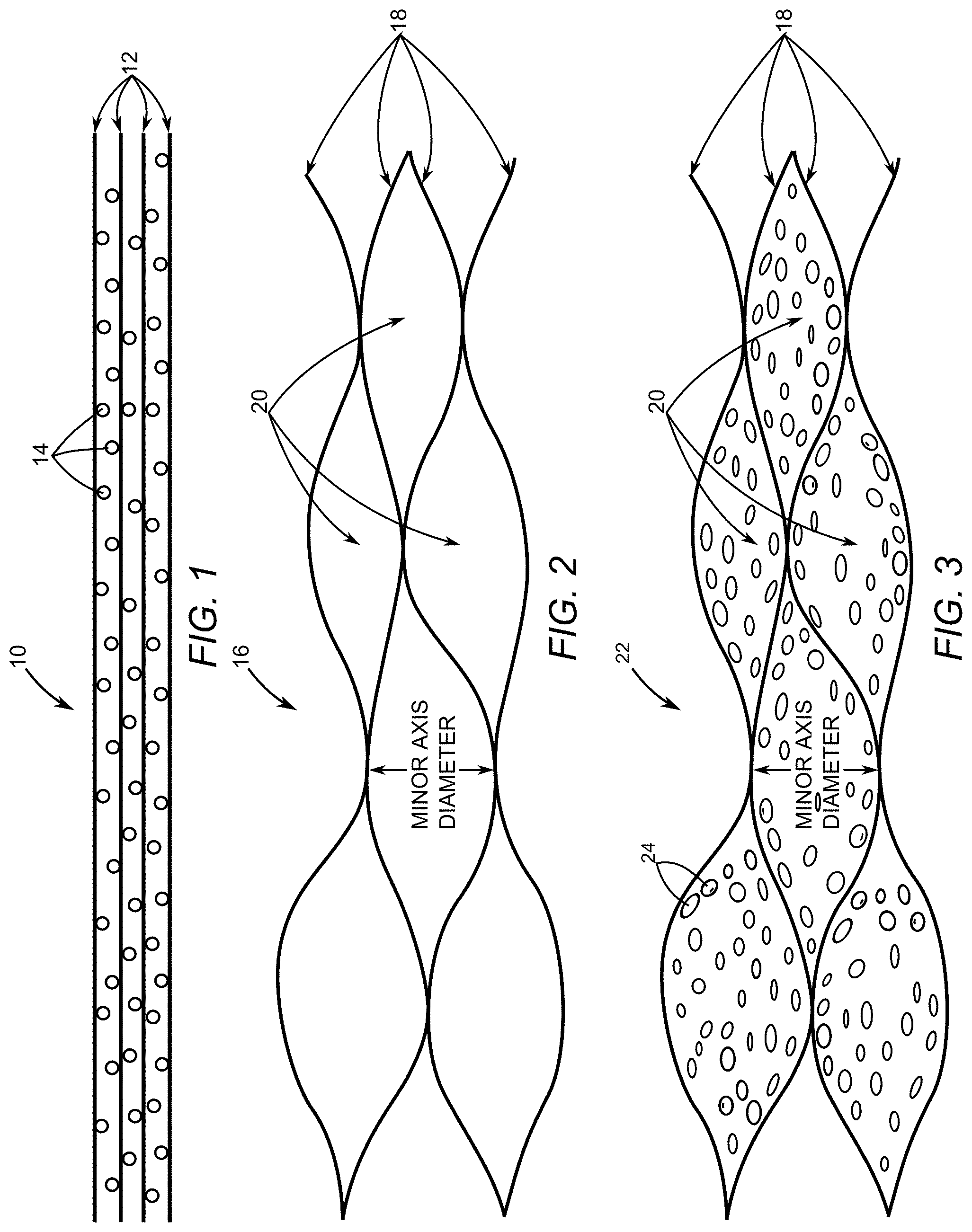
[0022] FIG. 1 depicts a cross-section of a carbon-based oxide flake.
[0023] FIG. 2 depicts a cross-section of a porous interconnected corrugated carbon-based network (ICCN) that results from deoxygenating the carbon-based oxide flake of FIG. 1.
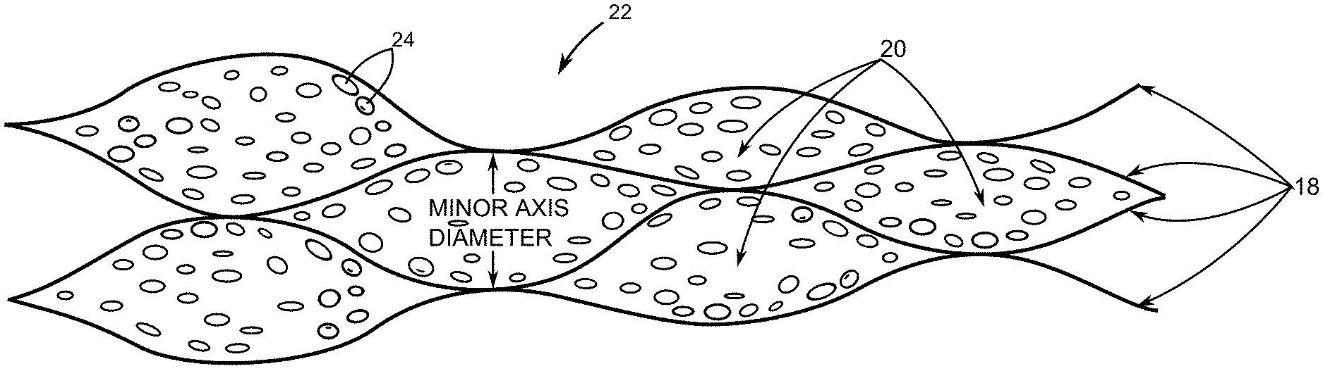
[0024] FIG. 3 depicts a cross-section of a porous ICCN composite that include metallic nanoparticles disposed within pores of the porous ICCN of FIG. 2.
[0025] FIG. 4 depicts a process for making a carbon-based film composite that contains carbon-based oxide flakes and a metallic precursor.
[0026] FIG. 5A depicts interdigitated electrodes formed using a computer directed laser to reduce portions of the carbon-based film composite of FIG. 4 into electrode patterns made of the porous ICCN composite of FIG. 3.
[0027] FIG. 5B is an exploded depiction of a micro-supercapacitor fabricated using the interdigitated electrodes depicted being formed in FIG. 5A.
[0028] FIG. 5B' is a top view depicting the interdigitated electrodes depicted in FIG. 5A.
[0029] FIG. 5C is an isometric view depicting the micro-supercapacitor of FIG. 5B fully assembled.
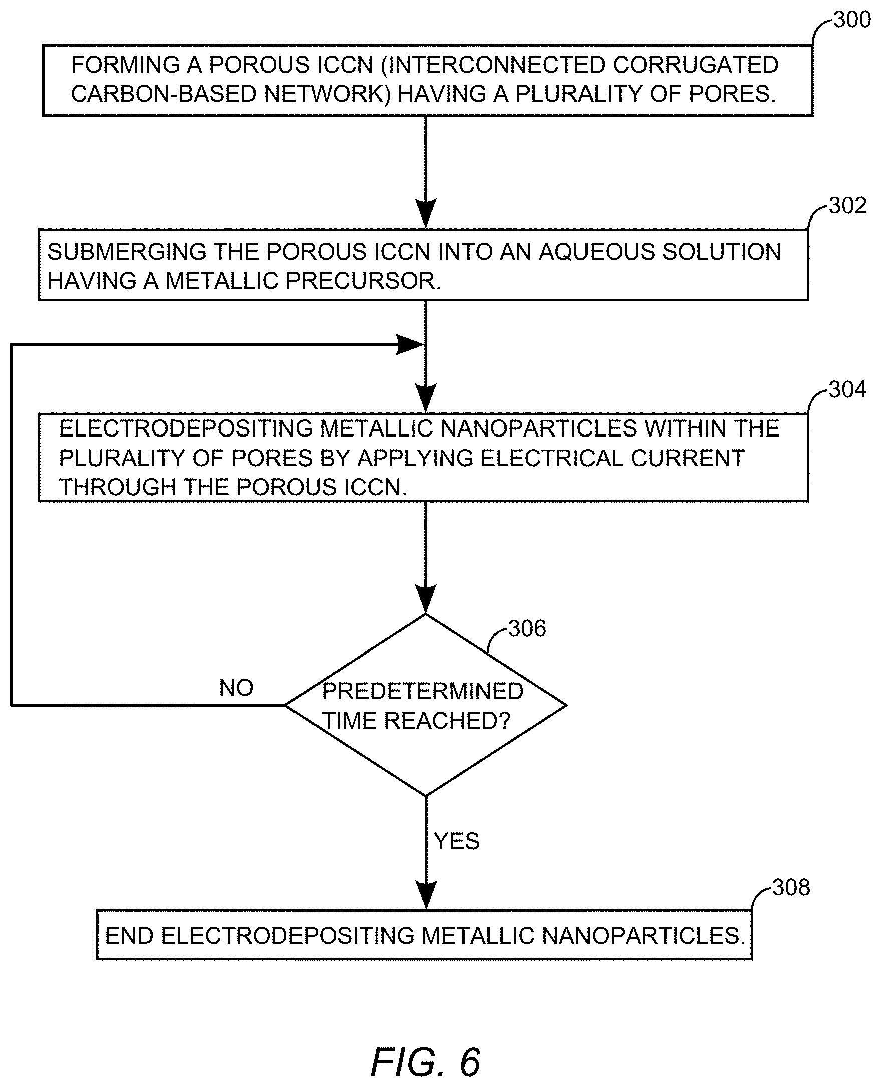
[0030] FIG. 6 is a flowchart that depicts an electrodeposition process for adding metallic nanoparticles to the porous ICCN of FIG. 2 to make the porous ICCN composite of FIG. 3.
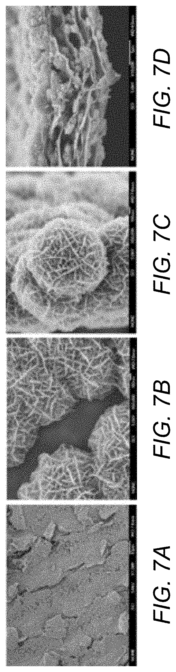
[0031] FIG. 7A is an SEM image of a portion of an electrode comprising porous ICCN composite.
[0032] FIG. 7B is a higher magnification of the SEM image of FIG. 7A.
[0033] FIG. 7C is an SEM image of a nanoflower morphology of electrodeposited MnO.sub.2.
[0034] FIG. 7D is a cross-sectional SEM image of porous ICCN composite.
DETAILED DESCRIPTION
[0035] The embodiments set forth below enable those skilled in the art to practice the disclosure. Upon reading the following description in light of the accompanying drawings, those skilled in the art will understand the concepts of the disclosure and will recognize applications of these concepts not particularly addressed herein. It should be understood that these concepts and applications fall within the scope of the disclosure and the accompanying claims.
[0036] It will be understood that when an element such as a layer, region, or substrate is referred to as being "over," "on," "in," or extending "onto" another element, it can be directly over, directly on, directly in, or extend directly onto the other element or intervening elements may also be present. In contrast, when an element is referred to as being "directly over," "directly on," "directly in," or extending "directly onto" another element, there are no intervening elements present. It will also be understood that when an element is referred to as being "connected" or "coupled" to another element, it can be directly connected or coupled to the other element or intervening elements may be present. In contrast, when an element is referred to as being "directly connected" or "directly coupled" to another element, there are no intervening elements present.
[0037] Relative terms such as "below" or "above" or "upper" or "lower" or "horizontal" or "vertical" may be used herein to describe a relationship of one element, layer, or region to another element, layer, or region as illustrated in the Figures. It will be understood that these terms and those discussed above are intended to encompass different orientations of the device in addition to the orientation depicted in the Figures.
[0038] For the purpose of this disclosure, in certain embodiments, the term expanded referring to a plurality of carbon layers that are expanded apart from one another means that the a portion of adjacent ones of the carbon layers are separated by at least 2 nanometers. Moreover, for the purpose of this disclosure, in certain embodiments the plurality of carbon layers is also defined as having an electrical conductivity greater than about 0.1 siemens/meter. Further still, each of the plurality of carbon layers is defined as being a two-dimensional material with only one carbon atom of thickness.
[0039] FIG. 1 depicts a cross-section of a flake of a carbon-based oxide 10 having a plurality of one atom thick carbon sheets 12. Oxygen atoms 14 are located between each of the plurality of one atom thick carbon sheets 12. A suitable material for the carbon-based oxide 10 is typically referred to as graphite oxide. Directing light having a power ranging from around about 5 milliwatts to around about 350 milliwatts causes the oxygen atoms to combine with some carbon atoms to form carbon dioxide gas that forces the plurality of one atom thick carbon sheets 12 to separate at locations. The carbon dioxide gas escapes from the carbon-based oxide 10 thereby deoxygenating the carbon-based oxide 10.
[0040] FIG. 2 depicts a cross-section of a porous interconnected corrugated carbon-based network (ICCN) 16 that results from deoxygenating the carbon-based oxide 10 of FIG. 1. The porous ICCN 16 comprises a plurality of expanded and interconnected carbon layers 18 that are interconnected and expanded apart from one another to form a plurality of pores 20. An average minor axis diameter of the plurality of pores 20 ranges between 2 nanometers and 550 nanometers. In an exemplary embodiment, the average minor axis diameter ranges between 50 nanometers and 500 nanometers.
[0041] FIG. 3 depicts a cross-section of a porous ICCN composite 22 that include metallic nanoparticles 24 disposed within the plurality of pores 20. The metallic nanoparticles 24 can be but are not limited to particles of manganese dioxide (MnO.sub.2), ruthenium dioxide (RuO.sub.2), cobalt oxide (Co.sub.3O.sub.4), nickel oxide (NiO), iron oxide (Fe.sub.2O.sub.3), copper oxide (CuO), molybdenum trioxide (MoO.sub.3), vanadium pentoxide (V.sub.2O.sub.5), nickel hydroxide (Ni(OH).sub.2), and combinations thereof. In yet other embodiments, the metallic nanoparticles are metal particles that include but are not limited to platinum (Pt), palladium (Pd), silver (Ag), gold (Au) and combinations thereof. Moreover, in at least some embodiments, the metallic nanoparticles have shapes that include but are not limited to nanoflower shapes, flake shapes and combinations thereof.
[0042] In at least one embodiment the porous ICCN composite 22 has an electrical conductivity greater than 900 siemens/meter. Moreover, a total surface area per unit mass of the plurality of expanded and interconnected carbon layers 18 is ranges between 1500 square meters per gram and 1620 square meters per gram. Further still, a percentage of surface area coverage of the metallic nanoparticles 24 onto the plurality of expanded and interconnected carbon layers 18 ranges between about 50% and 95%.
[0043] The porous ICCN composite 22, when charged in a capacitor configuration, provides an energy density that ranges between 2 Watt-hour/liter and 41 Watt-hour/liter. In at least some embodiments, the porous ICCN composite 22 when charged in a capacitor configuration provides an energy density that ranges between 2 Watt-hour/liter and 20 Watt-hour/liter. In yet other embodiments, the porous ICCN composite 22, when charged in a capacitor configuration, provides an energy density that ranges between 20 Watt-hour/liter and 41 Watt-hour/liter.
[0044] FIG. 4 depicts a process for making a film 26 of carbon-based composite that contains the carbon-based oxide 10 (FIG. 1) and a metallic precursor 28. The metallic precursor 28 can be but is not limited to ruthenium chloride hydrate (RuCl.sub.3), cobalt chloride (CoCl.sub.2), nickel chloride (NiCl.sub.2), vanadium chloride (VCl.sub.3), iron chloride (FeCl.sub.3), copper chloride (CuCl.sub.2), molybdenum chloride (MoCl.sub.3), hydrogen hexachloroplatinate (H.sub.2PtCl.sub.6), hexachloropalladate (H.sub.2PdCl.sub.6), hydrogen tetrachloroaurate (HAuCl.sub.4), and combinations thereof.
[0045] The process begins with providing the carbon-based oxide 10, a liquid 30, and metallic precursor 28 in solution 32 (step 100). The process continues by sonicating the solution 32 to increase dispersion and suspension of the metallic precursor 28 and the carbon-based oxide 10 (step 102). After sonication, the metallic precursor 28 is dispersed directly onto the carbon-based oxide 10. The process continues with drop-casting the solution onto a substrate 34 (step 104). Next, a step of evaporating the liquid 30 from the solution 32 is commenced (step 106). Evaporation of the liquid 30 can be forced drying using heat and airflow or natural drying in a relatively lower humidity environment. In at least one embodiment, the liquid 30 is deionized water.
[0046] FIGS. 5A-5C depict an exemplary process for fabricating a micro-supercapacitor 36 having a first electrode 38 and a second electrode 40 made from the porous ICCN composite 22 of FIG. 3. Electrode patterns 42 designed on a computer 44 can be patterned into the film 26 of carbon-based composite on the substrate 34 by using light to reduce portions of the film 26 of carbon-based composite into the first electrode 38 and the second electrode 40. The exemplary process begins when the computer 44 controls positioning and power of light 46 output from a light source 48 such that portions of the film 26 absorb the light 46 and are converted into porous ICCN composite(s) to realize the first electrode 38 and the second electrode 40 (step 200).
[0047] In this exemplary embodiment, the light source 48 is a laser diode that is positioned by the computer 44 radially along a radial path R and an arcuate path .theta.. By using the precision of a laser, a direct-to-disc labeling drive is usable to render computer-designed patterns such as the electrode patterns 42 into the film 26 of carbon-based composite to produce the first electrode 38 and the second electrode 40. The precision control of the light source 48 afforded by the computer 44 allows the first electrode 38 and the second electrode 40 to be interdigitated. The first electrode 38 and the second electrode 40 are transferred to a package substrate 50 as shown in FIG. 5B.
[0048] As best seen from a top view in FIG. 5B', the carbon-based oxide 10 serves as a good insulator between the first electrode 38 with electrode digits 38D and the second electrode 40 with electrode digits 40D. An exemplary length L for the electrode digits 38D and 40D is around 4800 micrometers. An exemplary width W for the electrode digits 38D and 40D is around 1770 micrometers. However, it is to be understood that the dimensions of the first electrode 38 and the second electrode 40 are scalable and only limited at nanoscales by the wavelength of light used to exfoliate the carbon-based oxide 10.
[0049] In particular, FIG. 5B shows an exploded view of the micro-supercapacitor 36 comprising the first electrode 38 and a second electrode 40 that are fabricated from porous ICCN composite 22 (FIG. 3) comprising a plurality of expanded and interconnected carbon layers 18 (FIG. 3) that are electrically conductive. The porous ICCN composite 22 has an electrical conductivity that ranges between 900 siemens/meter and about 1738 siemens/meter. Moreover, at least one of the first electrode 38 and the second electrode 40 provides a specific capacitance that ranges between 1100 Farads/gram and 1400 Farads/gram. It is to be understood that optionally either the first electrode 38 or the second electrode 40 can be made of a metal, while the remaining one of either the first electrode 38 or the second electrode 40 is made of porous ICCN composite 22. However, the first electrode 38 and the second electrode 40 are typically laser scribed from the film 26 that is transferred onto the substrate 50 such as Polyethylene terephthalate (PET) or silicon (Si) having an insulating layer 52 such as a silicon dioxide (SiO.sub.2) layer.
[0050] A first conductive strip 54 and a second conductive strip 56 are interfaced with the first electrode 38 and the second electrode 40 to provide electrically conductive terminals to couple to external circuitry (not shown). Exemplary external circuitry to be powered by the micro-supercapacitor 36 can be, but is not limited to, integrated circuits and other electrically powered micro-scale devices. A liner 58 that is non-electrically conductive covers the portions of the first electrode 38 and the second electrode 40 that are interfaced with the first conductive strip 54 and the second conductive strip 56. The liner 58 includes a central window through which an electrolyte 60 is placed in contact with the first electrode 38 and the second electrode 40. A polyimide tape can be used as the liner 58. The electrolyte is can be a gel electrolyte such as fumed silica (FS) nano-powder mixed with an ionic liquid. An exemplary ionic liquid is 1-butyl-3-methylimidazolium bis(trifluoromethylsulfonyl)imide. Another suitable gel electrolyte is a hydrogel such as poly(vinyl alcohol) (PVA)-H.sub.2SO.sub.4. Other electrolytes are also suitable, but the disclosed electrolytes provide a voltage window between a maximum charged voltage and a minimum discharged voltage of around about 2.5V.
[0051] FIG. 5C depicts the micro-supercapacitor 36 fully assembled. In this exemplary depiction, the first conductive strip 54 becomes a positive terminal and the second conductive strip 56 becomes a negative terminal. It is to be understood that the first conductive strip 54 and the second conductive strip 56 may be made from an electrical conductor such as copper (Cu), aluminum (Al), and/or additional structures comprised of the porous ICCN composite 22.
[0052] The first electrode 38 and the second electrode 40 can thus be directly used as components for planar micro-supercapacitors after receiving an electrolyte overcoat, as depicted in FIGS. 5B and 5C. Unlike conventional micro-fabrication methods, a direct laser scribing technique depicted in FIG. 5A does not require masks, expensive materials, post-processing or clean room operations. Furthermore, the direct laser scribing technique is cost effective and readily scalable.
[0053] Between a macro-scale and nano-scale is a sub-micron scale that includes a range of micro-supercapacitors that are usable to power integrated circuits. As such, these micro-supercapacitors can be integrated with integrated circuitry such that the integrated circuitry and micro-supercapacitors can be fabricated into a single integrated circuit package.
[0054] The porous ICCN composite 22 of the present disclosure is also usable to fabricate relatively large first and second electrodes separated by an electrolyte that provides enough charge storage capacity to power passenger car sized electric vehicles. Moreover, supercapacitors fabricated in accordance with the present disclosure are also usable to supply electrical power to industrial electrical power grids during peak power demands. For example, the first electrode 38 and the second electrode 40 of a supercapacitor according to the present disclosure can be sized to supply peak power to a megawatt capacity electrical power grid.
[0055] FIG. 6 is a flowchart that depicts an exemplary electrodeposition process for adding metallic nanoparticles to the porous ICCN 16 (FIG. 2) to make the porous ICCN composite 22 of FIG. 3. The electrodeposition process begins with forming the porous ICCN 16 (step 300). The porous ICCN 16 may be formed by exposing the carbon-based oxide 10 (FIG. 1) to light from the light source 48 (FIG. 5A). While at least one embodiment uses a laser for the light source 48, it is to be understood that a flash lamp as well as other equally high intensity sources of light are usable to reduce the carbon-based oxide to the porous ICCN 16. The electrodeposition process continues by submerging the porous ICCN 16 into an aqueous solution having a metallic precursor 28 (step 302). The porous ICCN 16 is used as a working electrode and electrodepositing metallic nanoparticles 24 with the plurality of pores 20 (FIGS. 2 and 3) is accomplished by applying electrical current through the porous ICCN 16 (step 304). Electrodeposition continues until a predetermined time is reached (step 306) when the electrodeposition is ended (step 308).
[0056] In at least one embodiment, the metallic particles electrodeposited in electrodepositing step 304 are manganese dioxide (MnO.sub.2) particles. In this case, the metallic precursor is 0.02 molar manganese nitrate (Mn(NO.sub.3).sub.2) in a 0.1 molar sodium nitrate (NaNO.sub.3) solution.
[0057] In an exemplary embodiment, a standard three electrode electrodeposition setup is usable for the electrodeposition of the metallic nanoparticles. For example, the porous ICCN 16 is used as a working electrode, silver (Ag) or silver chloride (AgCl) is used as a reference electrode, and a platinum foil is used as a counter electrode. An exemplary electrical current applied through the porous ICCN 16 has a current density of around about 250 microamperes per square centimeter. A predetermined time for applying the electrical current in the electrodepositing step (304) is proportional to the amount of metallic nanoparticle deposition desired. The predetermined time ranges from between about 3 minutes to around about 960 minutes. In one embodiment, the predetermined time ranges from 30 minutes to 240 minutes. In another embodiment the predetermined time ranges from 240 minutes to 480 minutes. In yet another embodiment, the predetermined time ranges from 480 minutes to 960 minutes. Within these predetermined time ranges for the electrodepositing step 304, a percentage of surface area coverage of the metallic nanoparticles electrodeposited onto the plurality of expanded and interconnected carbon layers 18 (FIG. 3) within pores 20 ranges from about 10% to around about 95%.
Synthesis and Characterization of 3D Macroporous ICCN/MnO.sub.2 Electrodes
[0058] To experimentally realize energy dense and high power supercapacitor electrodes, a highly conductive and high surface area 3D laser scribed graphene (LSG) framework that is a form of interconnected corrugated carbon-based network (ICCN) was integrated with MnO.sub.2 as schematically illustrated in FIG. 3. The ICCN was produced from the laser scribing of GO films following our previously reported method, upon which the color changes from golden brown to black. The ICCN was subsequently coated in situ with MnO.sub.2 using an electrochemical deposition technique as described in the Methods section below. Note that an ICCN electrode turns darker in color after electro-deposition, a visual indication of the loading of MnO.sub.2. It is well accepted that the conductivity and mass loading of the active materials have a significant impact on the electrochemical behavior of supercapacitor electrodes. Here, the mass loading of MnO.sub.2 is controlled by adjusting the deposition current and deposition time. The MnO.sub.2 loading changes almost linearly with the deposition time at an applied current of 0.25 mA/cm.sup.2 and an average deposition rate estimated to be .about.6 .mu.g/min.
[0059] In addition to interesting electrical properties, the ICCN/MnO.sub.2 electrodes are monolithic and demonstrate superb mechanical integrity under large mechanical deformation. An ICCN/MnO.sub.2 electrode can be bent significantly without damage. The foldability of ICCN/MnO.sub.2 electrodes was evaluated by measuring their electrical resistance under successive bending cycles. The resistance varies only slightly up to a bending radius of 5.0 mm and can be completely recovered after straightening no matter whether the bending is positive (convex) or negative (concave). Notably, after 1000 cycles of bending and straightening at a concave bend radius of 5.0 mm, the resistance has increased by only about 2.8%.
[0060] The evolution of morphology corresponding to different deposition times was examined by scanning electron microscopy, FIGS. 7A-D. FIG. 7A is an SEM image of a portion of an electrode comprising porous ICCN composite. FIG. 7B is a higher magnification of the SEM image of FIG. 7A. FIG. 7C is an SEM image of a nanoflower of electrodeposited MnO.sub.2. FIG. 7D is a cross-sectional SEM image of porous ICCN composite.
[0061] The SEM micrographs show the general morphology and detailed microstructure of a typical sample prepared by 120 minutes of deposition. MnO.sub.2 has been uniformly coated onto the surface of graphene throughout the entire film. Moreover, the electrodeposited MnO.sub.2 particles show a nanoflower-shaped hierarchical architecture with a clear interface between MnO.sub.2 and the graphene substrate, which is consistent with previous studies. Closer inspection of the MnO.sub.2 nanoflowers shows that they are made up of hundreds of ultrathin nanoflakes that are 10-20 nm thick. These nanoflakes are interconnected together to form mesoporous MnO.sub.2 with a large accessible surface area, thus offering numerous electroactive sites available to the electrolyte which promotes fast surface Faradaic reactions.
[0062] The 3D structure of ICCN/MnO.sub.2 electrodes was further analyzed using cross-sectional SEM, FIG. 7D. The 3D porous structure of ICCN is preserved after the deposition of MnO.sub.2 without any agglomerations. The ICCN surface has been uniformly coated with MnO.sub.2 over the entire cross-section. In addition, energy-dispersive X-ray spectroscopy (EDS) provides elemental maps of C, O and Mn, which confirms that a homogeneous coating of MnO.sub.2 throughout the 3D macroporous framework has been created.
[0063] XPS was successfully used for better understanding of the chemical composition and the oxidation state of Mn in the ICCN/MnO.sub.2 electrodes. The peaks of Mn 2p.sub.3/2 and Mn 2p.sub.1/2 are located at 642.1 and 653.9 eV, respectively, with a spin energy separation of 11.6 eV, which is in good agreement with data for Mn 2p states previously reported. Toupin et al. showed that the peak separation of the Mn 3s doublet is related to the oxidation state of Mn in manganese oxides, where reference samples of MnO, Mn.sub.3O.sub.4, Mn.sub.2O.sub.3 and MnO.sub.2 showed a separation of 5.79, 5.50, 5.41 and 4.78 eV, respectively. The as-prepared ICCN/MnO.sub.2 showed a separation energy of 4.8 eV for the Mn 3s doublet, suggesting that the oxide is MnO.sub.2 which was further confirmed from the O 1s spectrum.
Assembly and Electrochemical Performance of Symmetric ICCN/MnO.sub.2 Supercapacitors
[0064] In order to test the electrochemical performance of ICCN/MnO.sub.2 macroporous frameworks, a supercapacitor pouch cell was assembled from two symmetric electrodes separated by a Celgard M824 ion porous separator and impregnated with 1.0 M Na.sub.2SO.sub.4 electrolyte. The cells were tested by cyclic voltammetry (CV) over a wide range of scan rates from 1 mV/s-1000 mV/s. As an example, consider the ICCN/MnO.sub.2 sample with a deposition time of 3 minutes, the supercapacitor shows nearly rectangular CV profiles up to a scan rate as high as 1000 mV/s, indicating excellent charge storage characteristics and ultrafast response time for the electrodes. The capacitances of the devices made with different deposition times were calculated from CV profiles. Note that the capacitance was calculated using the total volume of the cell stack, rather than a single electrode. This includes the volume of the current collector, the active material, the separator and the electrolyte.
[0065] The capacitance depends strongly on the loading amount of the pseudo-capacitive MnO.sub.2 and increases significantly with deposition time from 0-960 min. For example, a stack capacitance of up to .about.203 F/cm.sup.3 can be achieved with the sample at a 960 min deposition time. This translates to a volumetric capacitance of 1136.5 F/cm.sup.3 when calculated based on the volume of the active material per electrode only. This value is much higher than the capacitance of activated carbons (60-80 F/cm.sup.3), carbide-derived carbons (180 F/cm.sup.3), bare ICCN (12 F/cm.sup.3), activated MEGO (60 F/cm.sup.3) and liquid mediated chemically converted graphene (CCG) films (263.3 F/cm.sup.3), indicating that the volumetric capacitance of carbon based electrodes can be significantly improved by incorporating pseudo-capacitive materials. Furthermore, this value is higher than some of the best values reported previously for MnO.sub.2 based supercapacitors: 16.1 F/cm.sup.3 for CNT/PPy/MnO.sub.2 sponge, 130 F/cm.sup.3 for graphene/MnO.sub.2/CNT, 246 F/cm.sup.3 for CNT/MnO.sub.2, 108 F/cm.sup.3 for meso-porous carbon/MnO.sub.2 and 90 F/cm.sup.3 for ultra-porous carbon/MnO.sub.2. In addition, depending on the deposition time, ultrahigh areal capacitances of up to .about.0.8 F/cm.sup.2 per footprint of the device can be achieved. This compares favorably with commercial carbon supercapacitors that typically provide .about.0.3 F/cm.sup.2.
[0066] This unprecedented performance can be understood by separating the contribution of the MnO.sub.2 nanoflowers from the average capacitance of the ICCN/MnO.sub.2 electrodes. The specific capacitance contributed by MnO.sub.2 alone was calculated by subtracting the charge of the bare ICCN according to the equation C.sub.s,MnO2=(Q.sub.ICCN/MnO2-Q.sub.ICCN)/(.DELTA.V.times.m.sub.MnO2). Here Q is the voltammetric charge, .DELTA.V is the operating potential window and m is the mass. The specific capacitance of MnO.sub.2 depends on the mass of the active material reaching a maximum value of 1145 F/g which is about 83% of the theoretical capacitance at a mass loading of 13% of MnO.sub.2. This remarkable performance can be attributed to the electrode microstructure that facilitates the transport of ions and electrons and provides abundant surfaces for charge-transfer reactions, ensuring a greater utilization of the active materials.
[0067] In order to demonstrate the superior properties of ICCN/MnO.sub.2 macroporous electrodes, MnO.sub.2 was also electrodeposited on both chemically converted graphene (CCG) and gold substrates under the same conditions. Not only does the CCG/MnO.sub.2 exhibit lower capacitance, but its performance falls off very quickly at higher charge/discharge rates. This can be attributed to the restacking of graphene sheets during the fabrication of the CCG electrodes, resulting in a significant reduction in the surface area and eventually closing off much of the porosity. In addition, the Au/MnO.sub.2 supercapacitor shows extremely low capacitance because of the limited surface area and structural properties. ICCN/MnO.sub.2, on the other hand, shows a stack capacitance of .about.50 F/cm.sup.3 that is more than four times higher than CCG/MnO.sub.2 and about three orders of magnitude higher than Au/MnO.sub.2. The enhanced capacitance and rate capability of the ICCN/MnO.sub.2 further confirms its optimized structure which synergizes the effects of both effective ion migration and high electroactive surface area, thus enabling high and reversible capacitive behavior even at high charge/discharge rates. The optimized ionic diffusion of the ICCN network was also confirmed from electrochemical impedance spectroscopy with a response time of 23 ms for ICCN compared to 5952 ms for the CCG electrodes. In fact, the ICCN/MnO.sub.2 supercapacitor shows superior volumetric capacitance and rate capability compared to commercially available activated carbon supercapacitors, pseudo-capacitors and lithium ion hybrid capacitors.
Construction of Asymmetric Supercapacitors
[0068] Construction of asymmetric supercapacitors. Asymmetric supercapacitors (ASCs) make use of positive and negative electrode materials of different types that can be charged/discharged in well-separated potential windows in the same electrolyte. They have attracted attention because they offer high capacity via a Faradaic reaction at the positive electrode and maintain fast charge/discharge due to the EDL mechanism at the negative electrode. Moreover, the asymmetric configuration can extend the operating voltage window of aqueous electrolytes beyond the thermodynamic limit of water (about 1.2 V), leading to significantly higher specific energy than symmetric supercapacitors using aqueous electrolytes. In fact, asymmetric supercapacitors based on carbon and NiOOH electrodes with an aqueous electrolyte are now commercially available from ESMA-ELTON. However, while this configuration ensures high capacitance, it has a low cell voltage (<1.5 V) that is detrimental to its energy and power performance. Considering the high pseudo-capacitance of the ICCN/MnO.sub.2 electrode and the fast charge/discharge of the double layer capacitance of the ICCN electrode, an asymmetric supercapacitor was assembled using ICCN/MnO.sub.2 as the positive and ICCN as the negative electrode. Here, a charge balance between the two electrodes was achieved by controlling the deposition time of MnO.sub.2 at the positive electrode and the thickness of the graphene film at the negative electrode. The electrochemical performance of an asymmetric cell that uses ICCN/MnO.sub.2 with 13% MnO.sub.2 mass loading (3 min deposition time) for the positive electrode cell exhibits an ideal capacitive behavior with nearly rectangular CV profiles and highly triangular CC curves. The CV profiles retain their rectangular shape without apparent distortions with increasing scan rates up to an ultrahigh rate of 10,000 mV/s, indicating the high rate capability of this asymmetric supercapacitor. Interestingly, the asymmetric cell presents a wide and stable operating potential window up to 2.0 V in aqueous electrolyte that should afford high energy density. Furthermore, as the MnO.sub.2 deposition time is increased from 3 min to 960 min, the stack capacitance increases significantly from around 3 to 76 F/cm.sup.3, meaning that the stored energy and power can be greatly improved in the asymmetric structure. These cells can also retain their high capacity when faster charge and discharge rates are needed. The as-fabricated supercapacitor is highly flexible and can be folded and twisted without affecting the structural integrity of the device. In addition, the supercapacitor delivers almost the same capacity even when placed under high bending conditions, holding promise as a practical energy storage system for flexible electronics.
[0069] Long cycle life is another important feature for commercially viable supercapacitors. Indeed, the asymmetric supercapacitor is very stable as it maintains over 96% of its original capacity after 10,000 charge/discharge cycles tested at a high scan rate of 1000 mV/s. The equivalent series resistance (ESR) of the supercapacitor was monitored during cycling using a Nyquist plot. The device demonstrates a slight increase of ESR in the first 1000 cycles with only subtle changes over the remaining cycles.
Three-Dimensional Interdigitated Micro-Supercapacitors
[0070] Three-dimensional interdigitated micro-supercapacitors. The development of miniaturized electronic systems such as smart sensors, implantable medical devices and micro-electromechanical systems (MEMS) has led to an increasing demand for microscale supercapacitors with high energy density in a limited space. This characteristic is crucial in the miniaturization of energy storage devices for modern electronic applications. Previous research has focused on increasing the micro-supercapacitor energy density by using different active materials such as activated carbon, graphene, carbon nanotubes, polymers and metal oxides. The development of micro-supercapacitors with high capacity per footprint area is crucial for the miniaturization of energy storage devices for modern electronic applications. Unfortunately, current state-of-the-art systems still suffer from low areal capacity: <11.6 mF/cm.sup.2 for carbons, and <78 mF/cm.sup.2 for conducting polymers and <56.3 for metal oxides. New hybrid micro-supercapacitors were fabricated, in which the positive and negative electrodes are separated into a 3D interdigitated structure. This structure was achieved by combining the techniques of "top down" LightScribe lithography with "bottom up" selective electro-deposition. First, 3D interdigitated ICCN microelectrodes were produced by the direct writing of graphene patterns on GO films using a consumer grade LightScribe DVD burner. A device fabricated comprises 16 in-plane microelectrodes (8 positive and 8 negative) separated by nearly insulating GO and the distance between the microelectrodes is close enough to keep the ion-transport pathway short. Subsequently, MnO.sub.2 nanoflowers were selectively electrodeposited on one set of the ICCN micro-electrodes using a standard 3-cell setup. The width of the micro-electrodes is adjusted to match the charge between the positive and negative poles of the micro-device. The lighter microelectrodes correspond to bare graphene (negative electrodes), whereas the other side turns darker in color after the electrodeposition of MnO.sub.2 (positive electrodes). The optical microscope image shows a well-defined pattern and sharp boundaries between the microelectrodes.
[0071] Electrochemical characterization shows that the asymmetric micro-supercapacitor provides enhanced volumetric capacitance and rate capability compared to a conventional sandwich-type asymmetric supercapacitor. Symmetric hybrid micro-supercapacitors show a similar behavior with the areal capacitance approaching 400 mF/cm.sup.2. This is likely due to the planar structure of the microdevices that results in better volumetric packing efficiency by eliminating the need for the polymer separator typically used in the sandwich structure to avoid short circuiting between electrodes. Moreover, the micro-scale architecture of the devices results in a significant reduction of the mean ionic diffusion pathway between the two microelectrodes. This is consistent with previous results with all-graphene micro-supercapacitors. This is believed to be the highest areal capacitance achieved so far in an interdigitated micro-supercapacitor. The stack capacitance significantly improves to -250 F/cm.sup.3 (volumetric capacitance per electrode is 1197 F/cm.sup.3) which is much higher than values previously reported for EDLC, pseudo- and hybrid micro-supercapacitors: 1.3 F/cm.sup.3 for carbon onions, 2.35-3.05 F/cm.sup.3 for graphene, 1.08 F/cm.sup.3 for CNT, 3.1 F/cm.sup.3 for graphene/CNT, 180 F/cm.sup.3 (electrode) for carbide-derived carbon, 588 F/cm.sup.3 for polyaniline nanofibers, 317 F/cm.sup.3 (electrode) for vanadium disulfide nanosheets and 178 F/cm.sup.3 for molybdenum disulfide nanosheets.
Discussion
[0072] The energy and power density of the ICCN/MnO.sub.2-based supercapacitors are superior to current technology. In order to put these results in perspective with current technology, a number of commercially available carbon-based supercapacitors, pseudo-capacitors, hybrid supercapacitors, and Li ion hybrid capacitors were characterized. These devices were tested under the same dynamic conditions as ICCN/MnO.sub.2. For all devices, the calculations were made based on the volume of the full cell that includes the current collector, active material, separator and electrolyte. The energy density of the hybrid ICCN/MnO.sub.2 varies between 22 to 42 Wh/l depending on the configuration (symmetric, asymmetric and sandwich, interdigitated) and the mass loading of MnO.sub.2. By comparison, the ICCN/MnO.sub.2 hybrid supercapacitors store about 6 times the capacity of state-of-the-art commercially available EDLC carbon supercapacitors. They are also superior to pseudo-capacitors, hybrid supercapacitors and supercapacitor/lithium ion battery hybrid (Li-ion capacitors). Furthermore, ICCN/MnO.sub.2 supercapacitors can provide power densities up to .about.10 kW/l, which is 100 times faster than high-power lead acid batteries and 1000 times faster than a lithium thin film battery.
[0073] To meet the high voltage requirements, supercapacitors are often put into a bank of cells connected together in series. This results in bulky supercapacitor modules which are appropriate in some cases, but often cause problems in applications where the total size of the power source is critical. Propose here is a different design in which an array of separate electrochemical cells are directly fabricated in the same plane and in one step. This configuration shows a very good control over the voltage and current output. In addition, this array can be integrated with solar cells for efficient solar energy harvesting and storage.
[0074] In summary, this disclosure provides a simple and scalable approach for the fabrication of hybrid ICCN/MnO.sub.2 three-dimensional supercapacitors and micro-supercapacitors that are compact, reliable, and energy dense, charge quickly, and possess long lifetime. Given that MnO.sub.2 is widely used in alkaline batteries (selling approximately 10 billion units per year (34)) and the scalability of carbon-based materials. In particular, ICCN/MnO.sub.2 hybrid electrodes offer promise for real world applications.
Materials and Methods
[0075] Synthesis of ICCN/MnO.sub.2, Au/MnO.sub.2 and CCG/MnO.sub.2 Electrodes
[0076] The ICCN was prepared by focusing a laser beam from a LightScribe
[0077] DVD burner on a DVD disc coated with graphite oxide. First, the DVD disc is covered by a film of gold coated polyimide (Astral Technology Unlimited, Inc.) or a sheet of polyethylene terephthalate. This was coated with a 2% GO dispersion in water using the doctor blade technique and left for drying for 5 hours under ambient conditions. A computer designed image is printed onto graphite oxide to make the appropriate ICCN pattern. This was followed by the electro-deposition of MnO.sub.2 from 0.02 M Mn(NO.sub.3).sub.2 in 0.1 M NaNO.sub.3 aqueous solution using a standard three electrode setup, where a piece of ICCN (1 cm.sup.2) is used as the working electrode, Ag/AgCl as the reference electrode (BASi, Indiana, USA) and a platinum foil (2 cm.sup.2, Sigma-Aldrich) as the counter-electrode. The deposition was achieved by applying a constant current of 250 .mu.A/cm.sup.2 for different time periods between 3 and 960 min. After electro-deposition, the working electrode was thoroughly washed with DI water to remove the excess electrolyte and dried in an oven at 60.degree. C. for 1 h. The amount of MnO.sub.2 deposited on the ICCN was determined from the difference in weight of the electrode before and after electro-deposition using a high precision microbalance with a readability of 1 .mu.g (Mettler Toledo, MX5).
[0078] For comparison, MnO.sub.2 was electrodeposited on other substrates such as gold-coated polyimide and graphene (CCG) paper. The gold-coated polyimide was obtained from Astral Technology Unlimited, Inc. (Minnesota, USA) and used without further treatment. The graphene paper was produced following our previously reported method. The gold-coated polyimide and graphene paper were cut into rectangular strips of 1 cm.sup.2 for further electro-deposition of MnO.sub.2 under the same conditions as described above.
Assembly of Sandwich-Type Hybrid Supercapacitors
[0079] Hybrid supercapacitors with the conventional sandwich structure were assembled using electrodes prepared in the previous section. Both symmetric and asymmetric supercapacitors were constructed. Symmetric supercapacitors were assembled by sandwiching a Celgard M824 (Celgard, North Carolina, USA) separator between two identical electrodes using 1.0 M Na.sub.2SO.sub.4 aqueous solution as the electrolyte. In the asymmetric structure, ICCN/MnO.sub.2 was used as the positive electrode and ICCN as the negative electrode. For the ICCN- and CCG-based supercapacitors, stainless steel (or copper) tape was attached to the electrodes, using silver paint, as the current collector. Before assembly, the electrodes were soaked in the electrolyte for 1 h to ensure proper wetting.
Fabrication of Interdigitated Hybrid Micro-Supercapacitors
[0080] The fabrication process of a micro-supercapacitor is illustrated in FIG. 5B and described below. First, ICCN interdigitated microelectrodes were printed directly on a GO film supported on a gold coated polyimide (or a polyethylene terephthalate) substrate using a consumer grade DVD burner. Second, MnO.sub.2 nanoflowers were grown on one set of the interdigitated electrodes using the electro-deposition setup described above. The applied current was normalized to the active ICCN deposition area at a current density of 250 .mu.A/cm.sup.2 and the mass loading was controlled by adjusting the deposition time. Likewise, symmetric micro-supercapacitors based on ICCN/MnO.sub.2 as both the positive and the negative electrodes were prepared as well. Here, the fabrication process is the same except that the two sides (instead of one side) of the bare interdigitated ICCN electrodes were connected together using copper tape and used as the working electrode during electro-deposition.
[0081] The hybrid electrodes embodied in the present disclosure can provide energy and power higher than that of any of the patented or published methods indicated in the subsequent reference lists. They are also superior to commercially available carbon-based supercapacitor, pseudo-capacitors, hybrid supercapacitors, and lithium ion capacitors tested under the same conditions.
[0082] The present disclosure describes a facile technique for the miniaturization of these hybrid supercapacitors to the microscale. These micro-supercapacitors enable an ultrahigh areal capacitance of more than 400 mF/cm.sup.2, which is higher than any performance achieved so far in the previous publications and patent applications. The hybrid supercapacitors can also provide an energy density of 22 Wh/l, more than two times higher than that of a lithium thin film battery. Clearly, the hybrid supercapacitors are advantageous compared with related art.
[0083] Another challenge is the working voltage of existing supercapacitors that is typically lower than 3 V, whereas capacitors used for general electronics applications typically range from a few volts to 1 kV. To solve this problem, the present disclosure describes, but is not limited to, one embodiment that is a different design in which an array of electrochemical cells is directly fabricated in the same plane and in one step. This configuration provides an operating voltage window of 6 V. In addition, the present disclosure describes a path to increase the voltage further. These arrays can be integrated with solar cells to produce efficient solar energy harvesting and storage systems.
[0084] Uses of the hybrid supercapacitors described in the present disclosure include, but are not limited to, the following areas: [0085] 1. Portable electronics: cellphones, computers, cameras, for example. [0086] 2. Medical devices: life-sustaining and life-enhancing medical devices including pacemakers, defibrillators, hearing aids, pain management devices, and drug pumps. [0087] 3. Electric vehicles: High-power batteries with long lifetime are needed to improve the electric vehicles industry. [0088] 4. Space: High-power batteries with long lifetime can be used in space to power space systems including rovers, landers, spacesuits, and electronic equipment. [0089] 5. Military batteries: The military uses special batteries for powering a huge number of electronics and equipment. Of course, reduced mass/volume is highly preferred. [0090] 6. Electric aircraft: an aircraft that runs on electric motors rather than internal combustion engines, with electricity coming from solar cells or batteries. [0091] 7. Grid scale energy storage: Batteries are widely used to store electrical energy during times when production (from power plants) exceeds consumption and the stored energy is used at times when consumption exceeds production. [0092] 8. Renewable energy: Since the sun does not shine at night and the wind does not blow at all times, batteries have found their way to off-the-grid power systems to store excess electricity from renewable energy sources for use during hours after sunset and when the wind is not blowing. Of course, high-power batteries can harvest energy from solar cells with higher efficiency than the current state-of-the-art batteries. [0093] 9. Power tools: High-power batteries with long lifetime would enable fast-charging cordless power tools such as drills, screwdrivers, saws, wrenches, and grinders. The trouble with current batteries is long recharging time. [0094] 10. Miniaturized electronics: The microscale hybrid supercapacitors can be used to provide power to microelectronic devices such as micro-electromechanical systems (MEMS), smart sensors, implantable medical devices, and radio frequency identification (RFID) tags for which high capacity per footprint is crucial.
[0095] Supercapacitors now play an important role in the progress of hybrid and electric vehicles, consumer electronics, military and space applications. There is a growing demand in developing hybrid supercapacitor systems to overcome the energy density limitations of the current generation of carbon-based supercapacitors. Here, we demonstrate 3D high-performance hybrid supercapacitors and micro-supercapacitors based on graphene and MnO.sub.2 by rationally designing the electrode microstructure and combining active materials with electrolytes that operate at high voltages. This results in hybrid electrodes with ultrahigh volumetric capacitance of over 1100 F/cm.sup.3. This corresponds to a specific capacitance of the constituent MnO.sub.2 of 1145 F/g, which is close to the theoretical value of 1380 F/g. The energy density of the full device varies between 22-42 Wh/l depending on the device configuration, which is superior to those of commercially available double layer supercapacitors, pseudo-capacitors, lithium ion capacitors and hybrid supercapacitors tested under the same conditions and is comparable to that of lead acid batteries. These hybrid supercapacitors use aqueous electrolytes and are assembled in air without the need for expensive `dry rooms` required for building today's supercapacitors. Furthermore, we demonstrate a simple technique for the fabrication of supercapacitor arrays for high voltage applications. These arrays can be integrated with solar cells for efficient energy harvesting and storage systems.
[0096] As a result of the rapidly growing energy needs of modern life, the development of high performance energy storage devices has gained significant attention. Supercapacitors are promising energy storage devices with properties intermediate between those of batteries and traditional capacitors, but they are being improved more rapidly than either. Over the past couple of decades, supercapacitors have become key components of everyday products by replacing batteries and capacitors in an increasing number of applications. Their high power density and excellent low temperature performance have made them the technology of choice for back-up power, cold starting, flash cameras, regenerative braking and hybrid electric vehicles. The future growth of this technology depends on further improvements in energy density, power density, calendar and cycle life and production cost.
[0097] According to their charge storage mechanism, supercapacitors are classified as either electric double layer capacitors (EDLCs) or pseudo-capacitors. In EDLCs, charge is stored through rapid adsorption/desorption of electrolyte ions on high-surface-area carbon materials, whereas pseudo-capacitors store charge via fast and reversible Faradaic reactions near the surface of metal oxides or conducting polymers. The majority of supercapacitors currently available in the market are symmetric EDLCs featuring activated carbon electrodes and organic electrolytes that provide cell voltages as high as 2.7 V (2). Although commercial EDLCs exhibit high power density and excellent cycle life, they suffer from low energy density because of the limited capacitance of carbon-based electrodes. The specific pseudo-capacitance of Faradaic electrodes (typically 300-1000 F/g) exceeds that of carbon-based EDLCs, however, their performance tend to degrade quickly up on cycling (2-4).
[0098] Studies during the past few years have demonstrated an attractive alternative to conventional EDLCs and pseudo-capacitors by employing hybrid systems. Utilizing both Faradaic and non-Faradaic processes to store charge, hybrid capacitors can achieve energy and power densities greater than EDLCs without sacrificing the cycling stability and affordability that have so far limited the success of pseudo-capacitors. Several combinations of materials, such as RuO.sub.2 (6), Co.sub.3O.sub.4 (7), NiO (8), V.sub.2O.sub.5 (9), Ni(OH).sub.2 (10), and MnO.sub.2 (11) have been studied for preparing hybrid supercapacitors. Among these, MnO.sub.2-based systems are particularly attractive as MnO.sub.2 is an earth abundant and environmentally friendly material with a high theoretical specific capacitance of 1380 F/g (12). However, the poor ionic (10.sup.-13 S/cm) and electronic (10.sup.-5-10.sup.-6 S/cm) conductivity of pristine MnO.sub.2 often limits its electrochemical performance. Recent reports show that some high-performance results can be achieved only from ultrathin MnO.sub.2 films that are a few tens of nanometers in thickness. Nevertheless, the thickness and the area-normalized capacitance of these electrodes are not adequate for most applications. A promising approach to realize practical applications of MnO.sub.2 is to incorporate nanostructured MnO.sub.2 on highly conductive support materials with high surface areas such as nickel foam, nickel nanocones, Mn nanotubes, activated carbon, carbon foam, carbon fabric, conducting polymers, carbon nanotubes and graphene. Although promising specific capacitances of 148-410 F/g have been achieved, such values were obtained only under slow charge/discharge rates and they were found to decrease rapidly as the discharge rate was increased. Moreover, many of these materials have low packaging density with large pore volume, meaning that a huge amount of electrolyte is needed to build the device, which adds to the mass of the device without adding any capacitance. Accordingly, the energy density and power density of these systems are very limited on the device level. To solve these critical problems, we have developed promising hybrid electrodes based on three-dimensional graphene doped with MnO.sub.2 nanoflowers. By rationally designing the structure of the graphene substrate to achieve high conductivity, suitable porosity, and high specific surface area, one may expect to not only achieve a high gravimetric capacitance, but also to improve the volumetric capacitance. Furthermore, the high surface area of nanostructured MnO.sub.2 provides more active sites for the Faradaic reactions and shortens the ion diffusion pathways that are crucial for realizing its full pseudo-capacitance. We show that hybrid supercapacitors based on these materials can achieve energy densities of up to 41 Wh/l compared to 7 Wh/l for state-of-the-art commercially available carbon-based supercapacitors. Interestingly, these graphene/MnO.sub.2 hybrid supercapacitors use aqueous electrolytes and are assembled in air without the need for the expensive "dry rooms" required for building today's supercapacitors.
[0099] While great efforts have been made for the fabrication of macro-scale hybrid supercapacitors, there are only a few studies on the design and integration of hybrid materials into micro-supercapacitors. This is likely due to complicated micro-fabrication techniques that often involve building 3D micro-electrodes with micro-meter separations. Here, we present a simple, yet versatile technique for the fabrication of 3D hybrid micro-supercapacitors based on graphene and MnO.sub.2. These micro-devices enable an ultrahigh capacitance per footprint approaching 400 mF/cm.sup.2, which is among the highest values achieved for any micro-supercapacitor. They can also provide an energy density of up to 22 Wh/l, more than two times that of lithium thin film batteries. These developments are promising for microelectronic devices such as biomedical sensors and radio frequency identification (RFID) tags where high capacity per footprint is crucial.
[0100] Rational design of high-performance hybrid supercapacitors. In designing supercapacitor electrodes, special efforts are made to ensure that they are capable of providing high energy density and high power density. This requires optimization of the preparation conditions to facilitate ionic and electronic transport within the electrodes. However, this is very challenging especially with metal oxide pseudo-capacitors because of the low electrical conductivity and long ionic diffusion pathways of conventional metal oxide films. Thus, in conventional compact MnO.sub.2 thick film electrodes, only the top layer is exposed to the electrolyte, meaning that a limited amount of the active material is involved in charge storage. To solve these problems, various approaches have been explored in the literature. For example, the electrochemical utilization of electrodes was improved by using nanostructured MnO.sub.2 such as nanoparticles, nanorods, nanowires and nanoflowers. The porous structure of these electrodes maximizes the area of active material that is exposed to the electrolyte and thus available to discharge compared to a solid electrode surface. Although this system exhibits higher energy density, it still suffers from the inherently low electrical conductivity of MnO.sub.2 leading to low power output. To improve the electrical conductivity of MnO.sub.2 film, conductive materials such as carbon powder, carbon nanotubes and graphene have been introduced into nanostructured MnO.sub.2 electrodes. However, the electronic charge carriers must move through small inter-particle contact areas which exhibit additional resistance resulting in poor electron transport from the electrode material to the current collector. An ideal electrode would be obtained by growing MnO.sub.2 nanostructures onto ICCN with high electrical conductivity and high surface area. In this structure, the conducting ICCN acts as a 3D current collector to provide electron "superhighways" for charge storage and delivery, while the nanostructured MnO.sub.2 enables fast, reversible Faradaic reactions with short ionic diffusion pathways. Another interesting feature of this structure is that each MnO.sub.2 nanoparticle is electrically connected to the current collector so that all the nanoparticles contribute to capacity with almost no "dead" mass.
[0101] Synthesis and characterization of 3D macroporous ICCN/MnO.sub.2 electrodes. To experimentally realize energy dense and high power supercapacitor electrodes, a highly conductive and high surface area ICCN was integrated with MnO.sub.2 as schematically illustrated in FIG. 3. The ICCN was produced from the laser scribing of carbon-based films such as graphite oxide
[0102] (GO) upon which the color changes from golden brown to black. The ICCN was subsequently coated in situ with MnO.sub.2 using an electrochemical deposition technique as described in the Methods section. This in situ growth technique enables MnO.sub.2 to be strongly anchored onto the ICCN, thus enabling reduced contact resistance and better electrochemical utilization of MnO.sub.2. The ICCN electrode turns darker in color after electro-deposition, a visual indication of the loading of MnO.sub.2. It is well accepted that the conductivity and mass loading of the active materials have a significant impact on the electrochemical behavior of supercapacitor electrodes. Here, the mass loading of MnO.sub.2 is controlled by adjusting the deposition current and deposition time. The MnO.sub.2 loading changes almost linearly with the deposition time at an applied current of 0.25 mA/cm.sup.2 and an average deposition rate estimated to be .about.6 .mu.g/min.
[0103] In addition to interesting electrical properties, the ICCN/MnO.sub.2 electrodes are monolithic and demonstrate superb mechanical integrity under large mechanical deformation. An ICCN/MnO.sub.2 electrode can be bent significantly without damage. The foldability of ICCN/MnO.sub.2 electrodes was evaluated by measuring their electrical resistance under successive bending cycles. The resistance varies only slightly up to a bending radius of 5.0 mm and can be completely recovered after straightening no matter whether the bending is positive (convex) or negative (concave. Notably, after 1000 cycles of bending and straightening at a concave bend radius of 5.0 mm, the resistance has increased by only about 2.8%. These measurements demonstrate the excellent electro-mechanical properties of ICCN/MnO.sub.2 electrodes, which is highly desirable for applications in flexible and wearable electronics.
[0104] The evolution of morphology corresponding to different deposition times was examined by scanning electron microscopy. The SEM micrographs show the general morphology and detailed microstructure of a typical sample prepared by 60 minutes of deposition. MnO.sub.2 has been uniformly coated onto the surface of graphene throughout the entire film. Moreover, the electrodeposited MnO.sub.2 particles show a nanoflower-shaped hierarchical architecture with a clear interface between MnO.sub.2 and the graphene substrate, which is consistent with previous studies. Closer inspection of the MnO.sub.2 nanoflowers shows that they are made up of hundreds of ultrathin nanoflakes that are 10-20 nm thick. These nanoflakes are interconnected together to form mesoporous MnO.sub.2 with a large accessible surface area, thus offering numerous electroactive sites available to the electrolyte which promotes fast surface Faradaic reactions.
[0105] The 3D structure of ICCN/MnO.sub.2 electrodes was further analyzed using cross-sectional SEM. The 3D porous structure of ICCN is preserved after the deposition of MnO.sub.2 without any agglomerations. The graphene surface has been uniformly coated with MnO.sub.2 over the entire cross-section. In addition, energy-dispersive X-ray spectroscopy (EDS) provides elemental maps of C, 0 and Mn, which confirms that a homogeneous coating of MnO.sub.2 throughout the ICCN has been created. As a control for comparison, the electrodeposition of MnO.sub.2 was carried out on both chemically converted graphene (CCG) and gold substrates. Unlike the ICCN, the electrodeposition of MnO.sub.2 occurs only on the top surface of the CCG, whereas a thick and compact film of MnO.sub.2 is deposited on gold. In addition, both the CCG/MnO.sub.2 and Au/MnO.sub.2 electrodes showed poor mechanical properties compared to ICCN/MnO.sub.2.
[0106] XPS was successfully used for better understanding of the chemical composition and the oxidation state of Mn in the ICCN/MnO.sub.2 electrodes. The Mn 2p and Mn 3s spectra. The peaks of Mn 2p.sub.3/2 and Mn 2p.sub.1/2 are located at 642.1 and 653.9 eV, respectively, with a spin energy separation of 11.6 eV, which is in good agreement with data for Mn 2p states previously reported. Toupin et al. showed that the peak separation of the Mn 3s doublet is related to the oxidation state of Mn in manganese oxides, where reference samples of MnO, Mn.sub.3O.sub.4, Mn.sub.2O.sub.3 and MnO.sub.2 showed a separation of 5.79, 5.50, 5.41 and 4.78 eV, respectively. The as-prepared ICCN/MnO.sub.2 showed a separation energy of 4.8 eV for the Mn 3s doublet, suggesting that the oxide is MnO.sub.2 which was further confirmed from the O 1s spectrum.
[0107] Assembly and electrochemical performance of symmetric ICCN/MnO.sub.2 supercapacitors. In order to test the electrochemical performance of ICCN/MnO.sub.2 macroporous frameworks, a supercapacitor pouch cell was assembled from two symmetric electrodes separated by a Celgard M824 ion porous separator and impregnated with 1.0 M Na.sub.2SO.sub.4 electrolyte. The cells were tested by cyclic voltammetry (CV) over a wide range of scan rates from 1 mV/s-1000 mV/s. As an example, consider the ICCN/MnO.sub.2 sample with a deposition time of 3 minutes, the supercapacitor shows nearly rectangular CV profiles up to a scan rate as high as 1000 mV/s, indicating excellent charge storage characteristics and ultrafast response time for the electrodes. The capacitances of the devices made with different deposition times were calculated from CV profiles. Note that the capacitance was calculated using the total volume of the cell stack, rather than a single electrode. This includes the volume of the current collector, the active material, the separator and the electrolyte.
[0108] The capacitance depends strongly on the loading amount of the pseudo-capacitive MnO.sub.2 and increases significantly with deposition time from 0-960 min. For example, a stack capacitance of up to .about.203 F/cm.sup.3 can be achieved with the sample at a 960 min deposition time. This translates to a volumetric capacitance of 1136.5 F/cm.sup.3 when calculated based on the volume of the active material per electrode only. This value is much higher than the capacitance of activated carbons (60-80 F/cm.sup.3), carbide-derived carbons (180 F/cm.sup.3), bare ICCN (12 F/cm.sup.3), activated MEGO (60 F/cm.sup.3) and liquid mediated CCG films (263.3 F/cm.sup.3), indicating that the volumetric capacitance of carbon based electrodes can be significantly improved by incorporating pseudo-capacitive materials. Furthermore, this value is higher than some of the best values reported previously for MnO.sub.2 based supercapacitors: 16.1 F/cm.sup.3 for CNT/PPy/MnO.sub.2 sponge, 130 F/cm.sup.3 for graphene/MnO.sub.2/CNT, 246 F/cm.sup.3 for CNT/MnO.sub.2, 108 F/cm.sup.3 for meso-porous carbon/MnO.sub.2 and 90 F/cm.sup.3 for ultra-porous carbon/MnO.sub.2. In addition, depending on the deposition time, ultrahigh areal capacitances of up to .about.0.8 F/cm.sup.2 per footprint of the device can be achieved. This compares favorably with commercial carbon supercapacitors that typically provide .about.0.3 F/cm.sup.2.
[0109] Supercapacitors are widely used in a variety of applications where a large amount of power is needed for a short period of time, where a very large number of charge/discharge cycles or a longer lifetime is required. However, the working voltage of existing supercapacitors is very low (<3 volts), whereas traditional capacitors used for general electronics applications typically range from a few volts to 1 kV. To meet the high voltage requirements, supercapacitors are often put into a bank of cells connected together in series. This results in bulky supercapacitor modules which are appropriate in some cases, but often cause problems in applications where the total size of the power source is critical. Here, we propose a different design in which an array of separate electrochemical cells are directly fabricated in the same plane and in one step. This configuration offers the flexibility of controlling the output voltage and current of the array. Compared with a single device with an operating voltage of 2 V, an array of 3 serial cells extends the output voltage to 6 V, whereas the output capacity (runtime) can be increased by a factor of 3 using an array of 3 cells connected in parallel. By using an array of 3 strings in parallel and 3 strings in series, the output voltage and current can both be tripled. Although the high-voltage supercapacitor array was demonstrated using a string of 3 cells, it is possible to increase the number of cells to reach an operating voltage of 100 V, which would be promising for a variety of applications.
[0110] With growing interest in "green" systems, solar power is gaining popularity for the implementation in more energy efficient buildings and smart cities. When combined with an energy storage system for storing energy during the day, they can be used to make self-powered systems that are promising for streetlight, industrial wireless monitoring, transportation and consumer electronics applications. Chemical batteries are often used in these systems due to their high energy density. Recently, supercapacitors are emerging as alternatives because they can capture energy more efficiently due to their short response time. These modules are struggling, though, because of the low energy density of existing supercapacitors. Since ICCN/MnO.sub.2 hybrid supercapacitors can provide higher energy density and because they can be fabricated in arrays with high voltage and current ratings, they can be integrated with solar cells for highly efficient energy harvesting and storage.
[0111] In summary, we have developed a simple and scalable approach for the fabrication of hybrid ICCN/MnO.sub.2 three-dimensional electrodes. ICCN with its high electrical conductivity and porous structure is demonstrated to be an excellent scaffold for MnO.sub.2 nanoparticles. The unique structure of these hybrid electrodes allows efficient use of the pseudo-capacitive properties of MnO.sub.2, while providing facilitated transport of both electrolyte ions and electrons. As a result, these supercapacitors exhibit high specific capacitance, an ultrafast charge/discharge rate, excellent cycling stability and high power density. They can store up to 6 times more charge than commercial carbon supercapacitors. These cells are fabricated in air without the need for expensive organic electrolytes or expensive dry rooms required for building today's supercapacitors. Given that MnO.sub.2 is widely used in alkaline batteries (selling approximately 10 billion units per year) and the scalability of graphene-based materials, we believe that graphene/MnO.sub.2 hybrid electrodes offer promise for real world applications.
[0112] Synthesis of ICCN/MnO.sub.2, Au/MnO.sub.2 and CCG/MnO.sub.2 electrodes. The ICCN was prepared using our previously reported method. A film of gold coated polyimide (Astral Technology Unlimited, Inc.) or polyethylene terephthalate was used as the substrate. This was followed by the electro-deposition of MnO.sub.2 from 0.02 M Mn(NO.sub.3).sub.2 in 0.1 M NaNO.sub.3 aqueous solution using a standard three electrode setup, where a piece of ICCN (1 cm.sup.2) is used as the working electrode, Ag/AgCl as the reference electrode (BASi, Indiana, USA) and a platinum foil (2 cm.sup.2, Sigma-Aldrich) as the counter-electrode. The deposition was achieved by applying a constant current of 250 .mu.A/cm.sup.2 for different time periods between 3 and 960 min. After electro-deposition, the working electrode was thoroughly washed with DI water to remove the excess electrolyte and dried in an oven at 60.degree. C. for 1 h. The amount of MnO.sub.2 deposited on the ICCN was determined from the difference in weight of the electrode before and after electro-deposition using a high precision microbalance with a readability of 1 .mu.g (Mettler Toledo, MX5).
[0113] For comparison, MnO.sub.2 was electrodeposited on other substrates such as gold-coated polyimide and graphene (CCG) paper. The gold-coated polyimide was obtained from Astral Technology Unlimited, Inc. (Minnesota, USA) and used without further treatment. The graphene paper was produced following our previously reported method. The gold-coated polyimide and graphene paper were cut into rectangular strips of 1 cm.sup.2 for further electro-deposition of MnO.sub.2 under the same conditions as described above.
[0114] Assembly of sandwich-type hybrid supercapacitors. Hybrid supercapacitors with the conventional sandwich structure were assembled using electrodes prepared in the previous section. Both symmetric and asymmetric supercapacitors were constructed. Symmetric supercapacitors were assembled by sandwiching a Celgard M824 (Celgard, North Carolina, USA) separator between two identical electrodes using 1.0 M Na.sub.2SO.sub.4 aqueous solution as the electrolyte. In the asymmetric structure, ICCN/MnO.sub.2 was used as the positive electrode and ICCN as the negative electrode. For the ICCN- and CCG-based supercapacitors, stainless steel (or copper) tape was attached to the electrodes, using silver paint, as the current collector. Before assembly, the electrodes were soaked in the electrolyte for 1 h to ensure proper wetting.
Characterization and Measurements
[0115] The morphology and microstructure of the different electrodes were investigated by means of field emission scanning electron microscopy (JEOL 6700) equipped with energy dispersive spectroscopy (EDS) and optical microscopy (Zeiss Axiotech 100). XPS analysis was performed using a Kratos Axis Ultra DLD spectrometer. The thicknesses of the different components of the device were measured using cross-sectional scanning electron microscopy and a Dektak 6 profilometer. The electrochemical performances of the ICCN-MSC supercapacitors were investigated by cyclic voltammetry (CV), galvanostatic charge/discharge tests and electrochemical impedance spectroscopy (EIS). CV testing was performed on a VersaSTAT3 electrochemical workstation (Princeton Applied Research, USA). Charge/discharge and EIS measurements were recorded on a VMP3 workstation (Bio-Logic Inc., Knoxville, Tenn.) equipped with a 10 A current booster. EIS experiments were carried out over a frequency range of 1 MHz to 10 mHz with an amplitude of 10 mV at open-circuit potential.
Porous ICCN Composite Pore Structure
[0116] Pore structure of porous ICCN was analyzed from two forms of carbon-based two dimensional materials, which are chemically converted graphene (CCG) films and laser scribed graphene (ICCN) films. The CCG sheets are well connected together in a layered structure to form the CCG electrodes. The reduced porosity and limited accessibility to electrolyte ions causes a slow frequency response of .about.5 seconds for CCG electrodes. ICCN electrodes, on the other hand, have a well-defined porous structure such that the individual graphene sheets in the ICCN network are accessible to the electrolyte, and thus exhibit a rapid frequency response of 23 ms. This causes the enhanced capacitance and rate capability observed with the ICCN/MnO.sub.2. The optimized structure of ICCN electrodes synergizes the effects of both effective ion migration and high electroactive surface area, thus enabling high and reversible capacitive behavior for ICCN/MnO.sub.2 even at high charge/discharge rates.
[0117] Further understanding of the capacitive behavior of the CCG/MnO.sub.2 and ICCN/MnO.sub.2 hybrid electrodes was obtained by conducting ac impedance measurements in the frequency range 1 MHz to 10 MHz. For each of these cells, MnO.sub.2 was electrodeposited for 120 min. The Nyquist plots consist of a spike at the low frequency region and a semicircle at the high frequency region. Compared with CCG/MnO.sub.2, the ICCN/MnO.sub.2 supercapacitor shows a much smaller diameter for the semicircle, which suggests a more efficient charge transfer on the electrode surface. Furthermore, in the low frequency region, a more vertical straight line is observed for the porous ICCN/MnO.sub.2 electrodes, indicating faster ion diffusion and almost ideal capacitive behavior for these electrodes. The intercept of the Nyquist curve on the real axis is about 1.5.OMEGA., indicating a high conductivity for the electrolyte and low internal resistance of the electrodes. These results show the strong impact of the microstructure of the graphene electrodes on the electrochemical performance of their composites with metal oxides.
[0118] Direct fabrication of hybrid micro-supercapacitor array for high voltage applications. It is highly desirable to develop supercapacitor arrays with large operating voltages to meet the energy and power requirements of the system on which it will be integrated. This is very important given that the working voltage of existing supercapacitors is relatively low (<3 volts), whereas capacitors used for general electronics applications typically range from a few volts to 1 kV. To meet the high voltage requirements, supercapacitors are often put into a bank of cells connected together in series. Here, we propose a different design in which an array of separate electrochemical cells are directly fabricated in the same plane.
[0119] First, circuits are designed using appropriate computer software and are directly patterned on a graphite oxide film coated on a DVD disc. It is also possible to design patterns to make a supercapacitor bank of series/parallel combinations in order to meet the voltage (series) and current (parallel) requirements of the system on which they will be integrated.
[0120] The second step is the deposition of MnO.sub.2 nanoflowers. Here, the deposition process varies depending on whether it is a symmetric or an asymmetric array. Ideally a gel electrolyte is used to prevent leakage into other cells in the array.
[0121] Calculations. The capacitances of the supercapacitors were calculated based on both cyclic voltammetry (CV) profiles and galvanostatic charge/discharge curves (CC). For the CV technique, the capacitance was calculated by integrating the discharge current (i) vs. potential (E) plots using the following equation:
C d e .nu. i c e = .intg. i d V .nu. .times. .DELTA. E ( 1 ) ##EQU00001##
where v is the scan rate (V/s) and .DELTA.E is the operating potential window.
[0122] The capacitance was also calculated from the charge/discharge (CC) curves at different current densities using the formula:
C d e .nu. i c e = i app dE / dt ( 2 ) ##EQU00002##
[0123] where i.sub.app is the current applied (in amps, A), and dV/dt is the slope of the discharge curve (in volts per second, V/s). Specific capacitances were calculated based on the area and the volume of the device stack according to the following equations:
Areal capacitance ( C A ) = C d e v i c e A ( 3 ) Volumetric stack capacitance ( C v ) = C d e v i c e V ( 4 ) ##EQU00003##
[0124] where A and V refer to the area (cm.sup.2) and the volume (cm.sup.3) of the device, respectively. The stack capacitances (F/cm.sup.3) were calculated taking into account the volume of the device stack. This includes the active material, the current collector and the separator with electrolyte.
[0125] The energy density of each device was obtained from the formula given in Equation (5):
E = 1 0 0 0 2 .times. 3 6 0 0 C v .DELTA. E 2 ( 5 ) ##EQU00004##
where E is the energy density in Wh/l, C.sub.v is the volumetric stack capacitance obtained from galvanostatic charge/discharge curves using Equation (3) in F/cm.sup.3 and .DELTA.E is the operating voltage window in volts.
[0126] The power density of each device was calculated using the equation:
P = E t ( 6 ) ##EQU00005##
where P is the power density in W/l and t is the discharge time in hours.
[0127] Since the majority of volumetric capacitances reported in the literature are based on the volume of the active material only, we applied the same calculations for the purpose of comparison using the following equations: Volumetric capacitance of the device,
C .nu. ( d e .nu. i c e ) = C device V ( 7 ) ##EQU00006##
where V is the volume of the active material on both electrodes Volumetric capacitance per electrode,
C.sub.v(electrode)=4.times.C.sub.v(device)(9) (8)
[0128] Asymmetric cells. In order to achieve optimal performance with asymmetric supercapacitors, there should be a charge balance between the positive and negative electrodes. The charge stored by each electrode depends on its volumetric capacitance (C.sub.v(electrode)), volume of the electrode (V), and the potential window in which the material operates (.DELTA.E).
q=C.sub.v(electrode).times.V.times..DELTA.E (9)
To attain the charge balance, the following condition must be satisfied
q + = q - ( 10 ) V + V - = C .nu. ( e l e c t r o d e ) - .times. .DELTA. E - C .nu. ( e l e c t r o d e ) + .times. .DELTA. E + ( 11 ) ##EQU00007##
The charge balance was achieved by adjusting the thickness of the positive and negative electrodes.
[0129] Comparison with commercial energy storage systems. In order to put the ICCN/MnO.sub.2 hybrid supercapacitors and micro-supercapacitors into perspective, we tested the performance of a wide range of commercially available energy storage systems for comparison. This includes activated carbon supercapacitors, a pseudo-capacitor (2.6 V, 35 mF), a battery-supercapacitor hybrid (lithium ion capacitor) (2.3 V, 220 F), an aluminum electrolytic capacitor (3 V, 300 .mu.F) and a lithium thin-film battery (4 V/500 .mu.Ah). Activated carbon supercapacitors of varying sizes were tested: small size (2.7 V, 0.05 F), medium size (2.7 V, 10 F) and large size (2.7 V, 350 F). The activated carbon large cell (2.7 V, 350 F) was tested at a lower current density of 160 mA/cm.sup.3 due to a limitation the measuring equipment that provides 10 A maximum current. All the devices were characterized under the same dynamic conditions as the ICCN/MnO.sub.2 hybrid supercapacitors and micro-supercapacitors.
[0130] Those skilled in the art will recognize improvements and modifications to the embodiments of the present disclosure. All such improvements and modifications are considered within the scope of the concepts disclosed herein and the claims that follow.
* * * * *
D00000
D00001
D00002
D00003
D00004
D00005
XML
uspto.report is an independent third-party trademark research tool that is not affiliated, endorsed, or sponsored by the United States Patent and Trademark Office (USPTO) or any other governmental organization. The information provided by uspto.report is based on publicly available data at the time of writing and is intended for informational purposes only.
While we strive to provide accurate and up-to-date information, we do not guarantee the accuracy, completeness, reliability, or suitability of the information displayed on this site. The use of this site is at your own risk. Any reliance you place on such information is therefore strictly at your own risk.
All official trademark data, including owner information, should be verified by visiting the official USPTO website at www.uspto.gov. This site is not intended to replace professional legal advice and should not be used as a substitute for consulting with a legal professional who is knowledgeable about trademark law.