System And Method For Determining At Least One Parameter Relating To An Angular Movement Of An Arbor
TORTORA; Pierpasquale ; et al.
U.S. patent application number 16/681148 was filed with the patent office on 2020-06-25 for system and method for determining at least one parameter relating to an angular movement of an arbor. This patent application is currently assigned to The Swatch Group Research and Development Ltd. The applicant listed for this patent is The Swatch Group Research and Development Ltd. Invention is credited to Pierpasquale TORTORA, Vittorio ZANESCO.
| Application Number | 20200201256 16/681148 |
| Document ID | / |
| Family ID | 64900810 |
| Filed Date | 2020-06-25 |


| United States Patent Application | 20200201256 |
| Kind Code | A1 |
| TORTORA; Pierpasquale ; et al. | June 25, 2020 |
SYSTEM AND METHOD FOR DETERMINING AT LEAST ONE PARAMETER RELATING TO AN ANGULAR MOVEMENT OF AN ARBOR
Abstract
A system and method to determine angular movement of an arbor integral with a crown of a watch, the arbor being rotatable on itself in a longitudinal direction. The system includes a rotating reflector mounted on the arbor, and two emitter/detector pairs disposed on either side of the reflector, each including a light source for illuminating the reflector, and a light detector for receiving the light reflected on the reflector and for generating an electrical signal representative of the reflected light. A processor processes the electrical signals, and determines a parameter relating to the angular movement of the arbor. The rotating reflector is a cylinder of revolution and light absorption points are made on the circumference of an external cylindrical surface. When the reflector rotates in a regular manner and in the same direction of rotation, the representative electrical signal generated by each detector has a sinusoidal shape.
| Inventors: | TORTORA; Pierpasquale; (Neuchatel, CH) ; ZANESCO; Vittorio; (Neuchatel, CH) | ||||||||||
| Applicant: |
|
||||||||||
|---|---|---|---|---|---|---|---|---|---|---|---|
| Assignee: | The Swatch Group Research and
Development Ltd Marin CH |
||||||||||
| Family ID: | 64900810 | ||||||||||
| Appl. No.: | 16/681148 | ||||||||||
| Filed: | November 12, 2019 |
| Current U.S. Class: | 1/1 |
| Current CPC Class: | G01D 5/3473 20130101; G04B 9/005 20130101; G04C 3/001 20130101 |
| International Class: | G04B 9/00 20060101 G04B009/00 |
Foreign Application Data
| Date | Code | Application Number |
|---|---|---|
| Dec 21, 2018 | EP | 18215436.9 |
Claims
1. A system (6) for determining at least one parameter relating to an angular movement of an arbor (4), particularly a stem (4) integral with a timepiece (1) crown (2), the system (6) comprising: an arbor (4) configured to be able to rotate on itself around a longitudinal direction (D1), a rotating reflector (8) mounted on the arbor (4), around said arbor (4), two emitter/detector pairs (10A, 10B), the two pairs (10A, 10B) being disposed on either side of the rotating reflector (8), facing the reflector (8), each emitter/detector pair (10A, 10B) including one light source (16) intended to illuminate one part of the reflector (8), and one light detector (18) intended to receive a reflected light beam (24) from the reflector (8) and to generate an electrical signal (26A, 26B) representative of said beam (24), and a processor configured to process each of the electrical signals generated by the detectors (18), and to determine, as a function of the processing result, said at least one parameter relating to the angular movement of the arbor (4), characterized in that the rotating reflector (8) is in the form of a cylinder of revolution, and an arrangement of light absorption points is made over the entire circumference of a reflective outer surface (12) of the cylinder of revolution, the absorption point arrangement on the outer surface (12) being such that, when the reflector (8) rotates on itself in a regular manner and in the same direction of rotation (S1, S2), the representative electrical signal (26A, 26B) generated by each detector (18) of each pair (10A, 10B) has a substantially sinusoidal shape.
2. The system (6) according to claim 1, characterized in that the two emitter/detector pairs (10A, 10B) are arranged with respect to the rotating reflector (8) such that the two emitters (16), respectively the two detectors (18), are arranged head-to-tail with respect to each other.
3. The system (6) according to claim 1, characterized in that the two emitter/detector pairs (10A, 10B) are disposed on either side of the rotating reflector (8), on a circle whose centre is substantially the centre (22) of the rotating reflector (8), and are offset from each other by an angle having a value other than 180.degree..
4. The system (6) according to claim 3, characterized in that the two emitter/detector pairs (10A, 10B) and the rotating reflector (8) are arranged to define a substantially Y-shaped spatial arrangement, the rotating reflector (8) being disposed at the centre of the Y, a first emitter/detector pair (10A) being disposed at the free end of a short arm of the Y, and the other emitter/detector pair (10B) being disposed at the free end of the long arm of the Y.
5. The system (6) according to claim 1, characterized in that, in each emitter/detector pair (10A, 10B), the emitter (16) and the detector (18) are optically isolated from each other.
6. The system (6) according to claim 1, characterized in that the rotating reflector (8) is made of metal, the outer surface (12) of the metal reflector being polished.
7. The system according to claim 1, characterized in that the points of the light absorption point arrangement over the entire circumference of the outer surface (12) of the cylinder of revolution, are obtained by etching using a laser controlled on the basis of a determined image defining a matrix of points or pixels, wherein the density of the absorption points varies in a sinusoidal manner.
8. The system according to claim 1, characterized in that the points of the light absorption point arrangement over the entire circumference of the outer surface (12) of the cylinder of revolution, are obtained by depositing points of black ink from a digital printer on the basis of a determined image defining a matrix of points or pixels, wherein the density of the absorption points varies in a sinusoidal manner.
9. The system (6) according to claim 7, characterized in that the density of the absorption points etched or printed over the entire circumference of the outer surfaces varies in two sine wave periods.
10. The system (6) according to claim 8, characterized in that the density of the absorption points etched or printed over the entire circumference of the outer surfaces varies in two sine wave periods.
11. A timepiece (1) comprising a system (6) for determining at least one parameter relating to an angular movement of an arbor (4), characterized in that system (6) conforms to claim 1.
12. The timepiece (1) according to claim 11, characterized in that the timepiece (1) is a quartz watch provided with a time-setting crown (2), said arbor (4) being the stem (4) integral with the crown (2).
13. A method for determining at least one parameter relating to the angular movement of an arbor (4), particularly a stem (4) integral with a crown (2) of a timepiece (1), by means of a determination system (6) according to claim 1, the method comprising the following steps, implemented by the processor: receiving (32) two electrical signals (26A, 26B) from two light detectors (18), each of the electrical signals (26A, 26B) being representative of a reflected light beam (24) from the reflector (8), each of the electrical signals (26A, 26B) having a substantially sinusoidal shape, determining (34) the frequency of each of the two received electrical signals (26A, 26B), determining (36), by comparison between the frequency determined by the processor and a correspondence table pre-stored in memory means of the system (6), the speed of rotation of the arbor (4).
14. The determination method according to claim 13, characterized in that the method further includes a step (38), implemented by the processor, consisting in representing the two received electrical signals (26A, 26B) as the sine and cosine of a same function and calculating an arctangent function (39) whose variable is the ratio between the two signals.
15. The determination method according to claim 14, characterized in that the method further includes a step (40), implemented by the processor, consisting in determining, according to the sign of the slope of the calculated arctangent function (39), the direction of rotation of the arbor (4).
16. The determination method according to claim 13, characterized in that the method further includes a step (30), implemented by the processor, consisting in alternately controlling the illumination of each of the light sources (16).
17. A computer program product comprising program instructions stored in memory means of a determination system and which, when executed by the determination system (6) processor, are able to implement the method according to claim 13, for the determination of at least one parameter relating to an angular movement of an arbor (4).
Description
CROSS-REFERENCE TO RELATED APPLICATIONS
[0001] This application claims priority to European Patent Application No. 18215436.9, filed on Dec. 21, 2018, the entire contents of which are incorporated herein by reference.
FIELD OF THE INVENTION
[0002] The invention concerns a system and a method for determining at least one parameter relating to an angular movement of an arbor able to rotate on itself. Such a parameter is, for example, the angular position, or speed of rotation, or direction of rotation of the arbor.
[0003] The invention also concerns a timepiece comprising the determination system. The timepiece is, for example, a quartz watch, the arbor then being the stem integral with a time-setting crown.
STATE OF THE ART
[0004] It is known to provide a watch, for example a quartz watch, with an electronic crown by means of which a user can set the time and thus the position of the hands, without contact with the gear train of the watch. To do so, an electronic or optical or electro-optical device is arranged inside the watch, which makes it possible to determine one or more parameters relating to the angular movement of the arbor integral with the crown, and thus to position the hands in the position desired by the user. More specifically, the rotational action of the crown made by the user is converted by the device into an electronic pulse to a watch processor, in order to communicate thereto how many steps and in which direction the hands must be turned. This type of coding may, for example, be achieved via a galvanic contact, a magnetic coil using the Hall effect, a capacitive device, or an electro-optical device implementing light signal transmission and detection.
[0005] Such an electro-optical device, in particular for determining the angular position and/or direction of rotation of the arbor integral with a watch crown, is, for example, disclosed in European Patent document No. EP 3 015 925 A1. The stem integral with the crown has a reflection surface on its external periphery. The device has a light source intended to illuminate the reflection surface, and a light detector intended to receive a reflected light beam from the reflection surface and to generate an electrical signal representative of the beam. The device further includes a processor configured to form, from the electrical signals received from the detector, at least two pixel patterns at two different instants. The processor is also configured to compare the successive pixel patterns, and to deduce therefrom at least one parameter relating to the angular movement of the stem if a shift occurs between the pixel patterns.
[0006] However, one drawback of the electro-optical device proposed in EP 3 015 925 A1 is that it generates relatively long processing times for the processor, due to the amount of data acquired. This solution thus requires providing sufficient power for the processor, which affects both the overall size of the latter and the power consumption of the device. Given that the space and energy available are particularly restricted in a watch, this may prove problematic for the overall dimensions of the system and its autonomy.
[0007] U.S. Pat. No. 9,797,753 B1 discloses an optical encoder for setting watch functions. The encoder includes a rotating shaft with a patterned surface, a light source for illuminating the patterned surface, an array of optical sensors for receiving a portion of a reflection of light on the patterned surface and a processor for processing the information from the optical sensors. A single light source is provided, which means that it is not possible to precisely and simply determine every angular movement of the rotating shaft.
SUMMARY OF THE INVENTION
[0008] It is thus an object of the invention to provide an electro-optical system for determining at least one parameter relating to an angular movement of an arbor able to rotate on itself, which makes it possible to operate with a limited amount of acquired data in order to reduce the processing power required, while ensuring precise and rapid determination of the parameter(s).
[0009] To this end the invention concerns a system for determining at least one parameter relating to an angular movement of an arbor, particularly an arbor integral with a timepiece crown, which includes the features mentioned in the independent claim 1.
[0010] Specific embodiments of the system are defined in the dependent claims 2 to 9.
[0011] Due to the pattern of absorption points made on the cylindrical surface of the rotating reflector, the light detectors of the system of the invention each generate a representative electrical signal, which has a substantially sinusoidal shape, when the reflector rotates on itself in a same direction of rotation. More precisely, the arrangement of light absorption points on the outer surface of the reflector, seen from each emitter/detector pair, changes when the reflector rotates on itself in a regular manner and such that the representative electrical signal generated by each detector has a substantially sinusoidal shape. Due to the substantially sinusoidal shape of the signals generated by the detectors, the processing performed by the system processor, to determine the parameter(s) relating to the angular movement of the arbor, is reduced. This makes it possible to determine the parameter(s) in a precise, reliable manner and with a limited amount of acquired data allowing a fast processing time, compactness and minimal energy consumption of the processor.
[0012] Advantageously, the two emitter/detector pairs are arranged with respect to the rotating reflector such that the two emitters, respectively the two detectors, are arranged head-to-tail with respect to the other. This makes it possible to introduce a phase shift between the signals generated by the two light detectors when the reflector rotates on itself. Such a phase shift makes it possible for the computer program implemented in the system memory means to determine the direction or speed of rotation of the arbor. Further, owing to this spatial arrangement of the two emitter/detector pairs, none of the light detectors misses the reflected light beam from the reflector.
[0013] Advantageously, the two emitter/detector pairs are arranged on either side of the rotating reflector, on a circle whose centre is substantially the centre of the rotating reflector, and are offset from each other by an angle having a value other than 180.degree.. This feature makes it possible to introduce a phase shift and/or to enhance the existing phase shift between the signals generated by the two light detectors when the reflector rotates on itself. Indeed, the two emitter/detector pairs do not see the reflector at the same angle, which introduces a phase shift between the generated signals. Preferably, the total phase shift created between the two signals is at least 25.degree., more preferably still substantially equal to 90.degree..
[0014] According to a particular technical feature of the invention, the rotating reflector is formed from a cylinder of revolution. The absorption point arrangement can be made by means of laser etching, or by the deposition of black points (ink) from a digital printer.
[0015] To this end, the invention also concerns a timepiece comprising the determination system described above, and which includes the features mentioned in the independent claim 10.
[0016] A particular embodiment of the timepiece is defined in the dependent claim 11.
[0017] To this end, the invention also concerns a method for determining at least one parameter relating to an angular movement of an arbor, particularly an arbor integral with a timepiece crown, by means of the determination system described above, and which includes the features mentioned in the independent claim 12.
[0018] Particular embodiments of the method are defined in the dependent claims 13 to 15.
[0019] Advantageously, the method further includes a step, implemented by the processor, consisting in representing the two received electrical signals as the sine and cosine of a same function and calculating an arctangent function whose variable is the ratio between the two signals. This makes it possible to determine the angular position of the arbor at any time and in an unequivocal manner.
[0020] Advantageously, the method further includes a step, implemented by the processor, consisting in determining, according to the sign of the slope of the calculated arctangent function, the direction of rotation of the arbor.
[0021] Advantageously, the method further includes a step, implemented by the processor, consisting in alternately controlling the illumination of each of the light sources. This prevents the detector of one of the emitter/detector pairs being affected by the light from the emitter of the other emitter/detector pair.
[0022] To this end the invention also concerns a computer program including program instructions stored in memory means of the determination system described above and which, when executed by the system processor, are capable of implementing the determination method as described above, and which includes the features mentioned in the independent claim 16.
BRIEF DESCRIPTION OF THE DRAWINGS
[0023] The objects, advantages and features of the determination system and method according to the invention, and of the timepiece containing the system, will appear more clearly in the following description, based on at least one non-limiting embodiment illustrated by the drawings, in which:
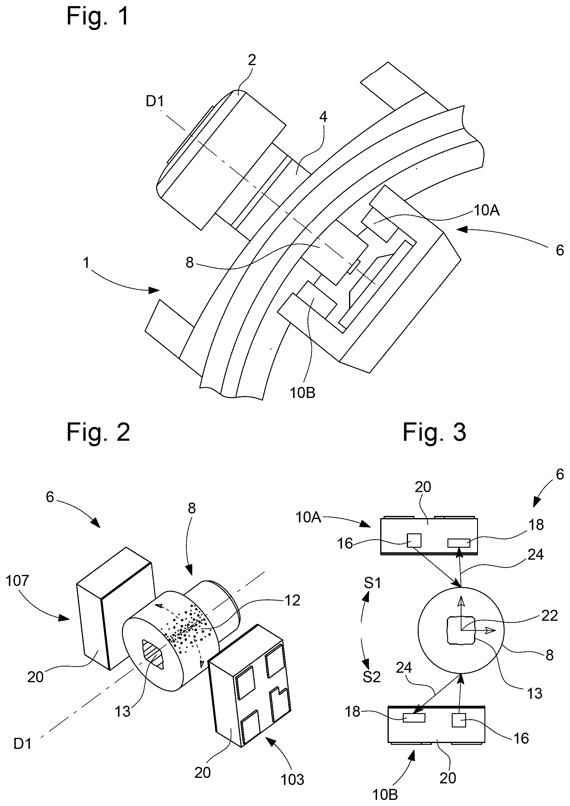
[0024] FIG. 1 is a perspective view of a watch provided with a time-setting crown, and a system for determining at least one parameter relating to an angular movement of the arbor integral with the crown, according to the invention.
[0025] FIG. 2 is a perspective view of the system of FIG. 1, the system comprising a rotating reflector and two emitter/detector pairs.
[0026] FIG. 3 is a front elevation view of the system of FIG. 2.
[0027] FIG. 4 is a perspective view of the rotating reflector of FIG. 2.
[0028] FIG. 5 represents a calculation of a matrix of black/white pixels to be etched or printed on the reflector wall in order to modulate the reflectivity of the surface thereof in a sine function.
[0029] FIG. 6 is a diagram representing the evolution of two electrical signals generated by the detectors of the two emitter/detector pairs as a function of the angular position of the rotating reflector.
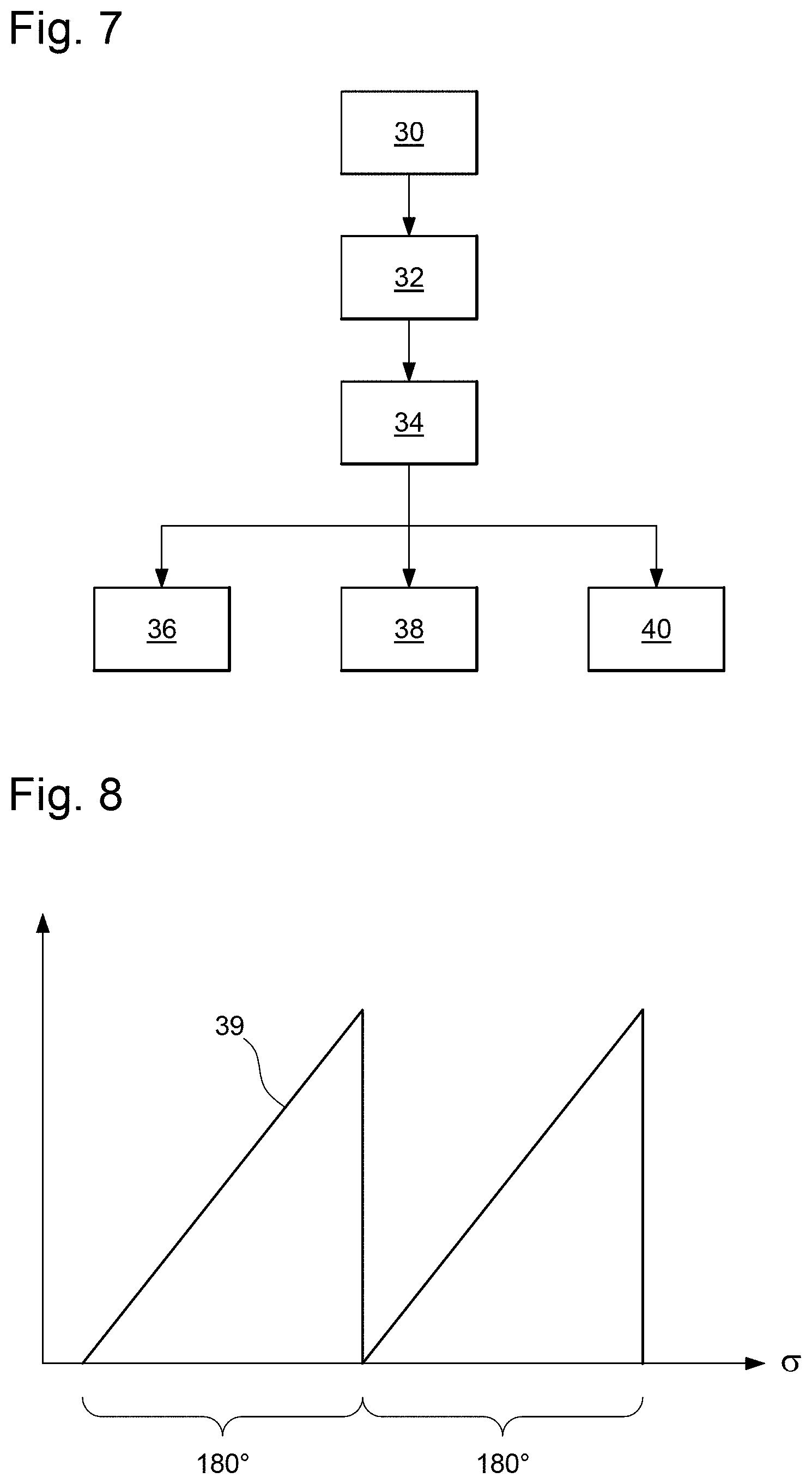
[0030] FIG. 7 is a flow chart representing steps of a method for determining at least one parameter relating to an angular movement of an arbor, implemented by the system of FIG. 1.
[0031] FIG. 8 is a diagram representing the evolution of an arctangent function calculated by a processor of the system of FIG. 2, as a function of the angular position of the rotating reflector.
DETAILED DESCRIPTION OF THE INVENTION
[0032] FIG. 1 represents a part of a watch 1 provided with a time-setting crown 2. Crown 2 is joined to an arbor 4 which extends partly inside watch 1, particularly inside the watch case. Watch 1, which is, for example, a quartz watch, further comprises a system 6 for determining at least one parameter relating to an angular movement of arbor 4 integral with crown 2.
[0033] Arbor 4 is able to rotate on itself around a longitudinal direction D1. More precisely, when crown 2 is rotated by a user to set the time, arbor 4 is driven in rotation on itself around direction D1. It is to be noted that, optionally, crown 2 can be configured to be pulled out and/or pushed in by a user, driving arbor 4 in longitudinal translation. When arbor 4 is fitted to a watch 1, as is the case in the illustrative example of FIGS. 1 to 4, the diameter of arbor 4 is typically comprised in a range from 0.5 to 2 mm.
[0034] As illustrated in FIGS. 2 and 3, in addition to arbor 4, system 6 includes a rotating reflector 8 and two light emitter/detector pairs 10A, 10B. System 6 also includes a processor and memory means but these elements are not represented in the Figures for reasons of clarity.
[0035] Rotating reflector 8 is mounted on arbor 4, around the latter. Rotating reflector 8 is thus integral with arbor 4. Rotating reflector 8 is, for example, mounted on an end portion of arbor 4, although this particular arrangement of reflector 8 on arbor 4 is not limiting in the context of the present invention. Reflector 8 and arbor 4 may also be made in one piece (not represented).
[0036] As shown in FIGS. 2 to 4, rotating reflector 8 is preferably formed from a cylinder of revolution. Peripheral surface 12 of reflector 8 is initially completely polished to have constant light reflectivity, like a mirror. This constant reflectivity is provided only by the material properties and surface quality. This cylindrical reflector 8 can, for example, have a diameter of 1.3 mm and a length of 0.77 mm. These dimensions are given merely for illustration without restriction for other values.
[0037] Rotating reflector 8 is, for example, metallic. The metal of reflector 8 is preferably chosen such that polished surface 12 reflects well in the wavelengths of light emitted by the light emitters. For example, for infrared light emitters, the metal chosen for reflector 8 may be a gold deposition. The choice of metal for reflector 8 is thus conditioned by the type of light emitters selected and can be adjusted according to the constraints of the product.
[0038] In a subsequent operation, an absorption point arrangement is arranged to be etched or deposited, notably by printing, for example, over the entire circumference of polished surface 12 of the cylinder of revolution. For purposes of simplification, this point arrangement is not completely shown in FIGS. 1 to 4, but is represented in FIG. 5, as explained below. Prior to making this light absorption point arrangement on the polished surface, a pattern of absorption points (black points) must be produced. This is obtained in the form of a 2D computer image for example, and more precisely a matrix of black/white pixels.
[0039] FIG. 5 represents a frequency sine function 2 to which an offset of 1 can be added so that the value is always positive. This sine function oscillates between 1 and 0. Frequency 2 means that over a complete revolution of reflector 8, there is detection of two complete sine waves of light beams reflected by the detectors, i.e. 180.degree. for each sine wave period. The matrix of points to be made on the polished surface of the cylinder is shown in a 2D image in the sine function graph. This 2D image must be reproduced over the entire peripheral circumference P of the polished surface of the cylinder of revolution and over a cylinder length L.
[0040] It is made in columns. The points where the function is 1, the reflectivity of the mirror must be maximum. Thus, in this column, no absorption pixel (black) will be made. However, where the function is 0, the reflectivity of the mirror must be minimum. Thus, all the pixels of this column will be black.
[0041] In terms of pixels, and in the example shown in FIG. 5, a reflectivity 1 means that, for example, 39 pixels of the column are all white. A reflectivity 0 means that, for example, 39 pixels of the column are all black. The intermediate cases are treated as follows. If, at a certain point, the value of the function is 0.6, this means that 60% of the pixels must stay white (23 pixels) and 40% of them must be black (16 pixels). In the non-limiting example represented, the cylinder has a peripheral circumference P equal to 4 mm and a length L equal to 0.77 mm. The initial image is composed of a rectangle of 4 mm by 0.77 mm, thus 200 times 39 pixels. These pixels or points in such case are 20 .mu.m by 20 .mu.m.
[0042] The object of this arrangement of points on reflector 8 is to obtain a signal, particularly a sinusoidal signal, at the detection of light by each detector 18 of the emitter/detector pairs. To this end, reflector 8 rotates on itself in a regular manner, notably at almost constant speed and in the same direction of rotation, and on the basis of a variation in light reflectivity.
[0043] The image presented in FIG. 5 can be etched or printed on the polished surface of reflector 8 in the form of a cylinder of revolution. The absorption points can be etched, for example, by a laser beam. If each (black) absorption point has a size of 20 .mu.m by 20 .mu.m, the etching laser beam can be a 20 .mu.m spot controlled from the computer by a control unit. This 2D image is uploaded into the laser control unit and then etched on the cylinder wall using a rotating stand synchronized with the laser emission.
[0044] It is to be noted that it is well known that it is possible to modify the optical properties of the surface of a material using the action of a laser beam. A laser can thus be used to locally etch absorption points on the reflector surface. The laser settings are kept constant during machining of the component so that each black point absorbs light with uniform efficiency. In such conditions, the variation in reflectivity is due only to the density of black points as represented in FIG. 5. Gradually, as the reflector rotates facing the light emitter, the density of the absorption points varies, and this produces a variation in the light reflected and sent to the corresponding detector. As indicated, this variation in reflected light generates a detection signal, which may be sinusoidal depending on the arrangement of absorption points made on the reflector which rotates on itself and in the same direction of rotation. It is also possible to envisage having an absorbent surface, for example using a PVD treatment, wherein the etching, for example by laser, exposes reflection points and not absorption points.
[0045] As shown in FIGS. 1 to 3 and partly explained above, each emitter/detector pair 10A, 10B includes one light source 16 and one light detector 18. Light source 16 is typically formed of one or more light emitting diodes, able, for example, to emit infrared light. Light source 16 and light detector 18 are arranged in a protective case 20 and are preferably optically isolated from each other, for example by means of a separating wall. Each emitter/detector pair 10A, 10B forms, for example, a proximity sensor unit device.
[0046] The two emitter/detector pairs 10A, 10B are disposed on either side of rotating reflector 8, facing reflector 8. In a preferred embodiment represented in FIG. 3, the two emitter/detector pairs 10A, 10B are arranged with respect to rotating reflector 8 such that the two emitters 16, respectively the two detectors 18, are arranged head-to-tail with respect to each other. Preferably, as illustrated in FIG. 3, the two emitter/detector pairs 10A, 10B are placed on a circle, whose centre is substantially the centre 22 of rotating reflector 8, and are offset from each other by an angle having a value other from 180.degree..
[0047] Also, preferably, as visible in FIG. 3, the two emitter/detector pairs 10A, 10B and rotating reflector 8 are arranged to define a substantially Y-shaped spatial arrangement. More precisely, rotating reflector 8 is disposed at the centre of the Y, a first emitter/detector pair 10A is disposed at the free end of a short arm of the Y, and the other emitter/detector pair 10B is disposed at the free end of the long arm of the Y. In other words, as seen in FIG. 3, the two emitter/detector pairs 10A, 10B are disposed on either side of rotating reflector 8 and are axially offset from each other.
[0048] Each light source 16 is intended to illuminate one part of reflector 8. Each light detector 18 is intended to receive a reflected light beam 24 from reflector 8 and to generate an electrical signal representative of beam 24. The representative electrical signal generated by each detector 18 has a substantially sinusoidal shape when reflector 8 rotates on itself in a same direction of rotation S1, S2. Such a signal 26A, 26B is, for example, visible in FIG. 6.
[0049] The processor is configured to process each of the electrical signals 26A 26B generated by detectors 18. The processor is also configured to determine, according to the processing result, at least one parameter relating to the angular movement of arbor 4, as will be explained in detail below. The parameter(s) determined are, for example, the angular position, speed of rotation, or the direction of rotation of arbor 4.
[0050] FIG. 6 represents two real signals 26A, 26B from detectors 18, at different angles corresponding to a rotation of rotating reflector 8 on itself. Each signal 26A, 26B is from a respective detector 18 of one of the emitter/detector pairs 10A, 10B. Each signal 26A, 26B has a substantially sinusoidal shape. Further, in the illustrative example of FIG. 6, signals 26A, 26B are phase shifted from each other by around 25.degree.. Preferably, signals 26A, 26B are phase shifted by at least 25.degree. and preferably substantially 90.degree..
[0051] A method according to the invention for determining at least one parameter relating to an angular movement of arbor 4, implemented by the processor of system 6, will now be described with reference to FIGS. 7 and 8. It is assumed, initially, that a user manipulates arbor 4 to rotate it on itself around longitudinal direction D1, for example by manipulating crown 2 to set the time of a watch 1. This rotation of arbor 4 causes a rotation of rotating reflector 8 around longitudinal direction D1.
[0052] Preferably, the method includes an initial step 30 during which the processor alternately controls the illumination of each of light sources 16.
[0053] During an initial or subsequent step 32, the processor receives two electrical signals 26A, 26B from the two light detectors 18. Each of electrical signals 26A, 26B is representative of a reflected light beam 24 from reflector 8 and has a substantially sinusoidal shape.
[0054] During a next step 34, the processor determines the frequency of each of the two received sinusoidal signals 26A, 26B.
[0055] During a next step 36, the processor determines the speed of rotation of arbor 4, by comparison between the frequency determined during step 34 and a correspondence table pre-stored in the system memory means.
[0056] Preferably, the method includes a parallel or next step 38, during which the processor represents the two received electrical signals 26A, 26B as the sine and cosine of a same function, then calculates an arctangent function whose variable is the ratio between the two signals. The result of this calculation is represented in FIG. 8 for the particular example embodiment of signals 26A, 26B represented in FIG. 6. It is noted that, over a half period of revolution of rotating reflector 8 corresponding to 180.degree., the curve 39 obtained is a straight line. Thus, the processor, which has access to a given value of a calculated arctangent function, can deduce therefrom the angular position of arbor 4, in an unequivocal manner. Further, the sign of the slope of the straight line obtained is a function of the direction of rotation of arbor 4. Thus, the method can comprise a parallel or next step 40 during which the processor determines, as a function of the sign of the slope of the straight line obtained, the direction of rotation of arbor 4.
[0057] It is to be noted that, to obtain the shape of curve 39 represented in FIG. 8, signals 26A, 26B must be phase shifted, preferably by at least 25.degree.. Such a phase shift is obtained by the head-to-tail arrangement of emitter/detector pairs 10A, 10B, as described above, and/or by the non-symmetrical arrangement of the two emitter/detector pairs 10A, 10B on either side of rotating reflector 8, as described above. Thus, the resulting phase shift between signals 26A, 26B makes it possible to obtain the shape of curve 39 represented in FIG. 8, and consequently allows the processor to precisely determine the angular position and direction of rotation of arbor 4.
[0058] The memory means store a computer program product comprising program instructions, which, when executed by the processor of system 6, are capable of implementing the method as described above.
[0059] It is to be noted that the algorithm described above for generating the reflectivity image remains generally valid also when the pattern on the cylindrical reflector is made with techniques other than laser. For example, the black pixels could thus be made using a black ink ejected by a digital printer.
[0060] It is also to be noted that the same algorithm can be used to make other reflectivity images and to generate other signals in the detector such as a square wave or a ramp. However, it is more difficult to easily determine the speed of rotation of the arbor or stem integral with the crown.
* * * * *
D00000
D00001
D00002
D00003
XML
uspto.report is an independent third-party trademark research tool that is not affiliated, endorsed, or sponsored by the United States Patent and Trademark Office (USPTO) or any other governmental organization. The information provided by uspto.report is based on publicly available data at the time of writing and is intended for informational purposes only.
While we strive to provide accurate and up-to-date information, we do not guarantee the accuracy, completeness, reliability, or suitability of the information displayed on this site. The use of this site is at your own risk. Any reliance you place on such information is therefore strictly at your own risk.
All official trademark data, including owner information, should be verified by visiting the official USPTO website at www.uspto.gov. This site is not intended to replace professional legal advice and should not be used as a substitute for consulting with a legal professional who is knowledgeable about trademark law.