Imaging Optical System And Image Projection Apparatus
IMAOKA; Takuya
U.S. patent application number 16/806038 was filed with the patent office on 2020-06-25 for imaging optical system and image projection apparatus. The applicant listed for this patent is Panasonic Intellectual Property Management Co., Ltd.. Invention is credited to Takuya IMAOKA.
| Application Number | 20200201007 16/806038 |
| Document ID | / |
| Family ID | 60267626 |
| Filed Date | 2020-06-25 |


View All Diagrams
| United States Patent Application | 20200201007 |
| Kind Code | A1 |
| IMAOKA; Takuya | June 25, 2020 |
IMAGING OPTICAL SYSTEM AND IMAGE PROJECTION APPARATUS
Abstract
An imaging optical system includes a plurality of lens groups each moving such that spaces between each one of the plurality of lens groups change during a zooming. The imaging optical system conjugates a conjugate point on a magnification side and an intermediate imaging position, and conjugates a conjugate point on a reduction side and the intermediate imaging position. The imaging optical system includes a first lens group located at a furthest place on the magnification side and a rear group in this order from the magnification side toward the reduction side. The first lens group includes a field curvature correction lens group moving along an optical axis when an amount of a field curvature is changed, and a focusing lens group. The imaging optical system satisfies condition (4) below: |{(1-.beta.cw.sup.2).times..beta.crw.sup.2}/{(1-.beta.fw.sup.2).times..b- eta.frw.sup.2}|<0.2 (4)
| Inventors: | IMAOKA; Takuya; (Kanagawa, JP) | ||||||||||
| Applicant: |
|
||||||||||
|---|---|---|---|---|---|---|---|---|---|---|---|
| Family ID: | 60267626 | ||||||||||
| Appl. No.: | 16/806038 | ||||||||||
| Filed: | March 2, 2020 |
Related U.S. Patent Documents
| Application Number | Filing Date | Patent Number | ||
|---|---|---|---|---|
| 16137637 | Sep 21, 2018 | 10620411 | ||
| 16806038 | ||||
| PCT/JP2017/017794 | May 11, 2017 | |||
| 16137637 | ||||
| Current U.S. Class: | 1/1 |
| Current CPC Class: | G02B 13/16 20130101; G02B 13/18 20130101; G02B 27/0068 20130101; G02B 15/20 20130101; G03B 21/142 20130101; G02B 15/173 20130101 |
| International Class: | G02B 15/20 20060101 G02B015/20; G03B 21/14 20060101 G03B021/14; G02B 27/00 20060101 G02B027/00; G02B 13/16 20060101 G02B013/16; G02B 15/173 20060101 G02B015/173; G02B 13/18 20060101 G02B013/18 |
Foreign Application Data
| Date | Code | Application Number |
|---|---|---|
| May 13, 2016 | JP | 2016-096657 |
Claims
1-19. (canceled)
20. An imaging optical system comprising a plurality of lens groups, the plurality of lens groups each including at least one lens and moving such that spaces between each one of the plurality of lens groups change during a zooming action, wherein the imaging optical system conjugates a conjugate point on a magnification side of the imaging optical system and an intermediate imaging position inside the imaging optical system, and conjugates a conjugate point on a reduction side of the imaging optical system and the intermediate imaging position, wherein the imaging optical system includes a first lens group located at a furthest place on the magnification side and having positive power, a second lens group having positive power, third lens group having positive power and a rear group having positive power in this order from the magnification side toward the reduction side, wherein the first lens group includes a focusing lens group moving along the optical axis during a focusing action from an infinity focus state to a proximate focus state, wherein the imaging optical system satisfies condition (9) below: 0.4<f4/bf<1.0 (9) where, f4 is a focal length of the rear lens group, and bf is a distance from a surface of a lens having power and located furthest on the reduction side to an imaging position on the reduction side.
21. The imaging optical system according to claim 20, wherein the intermediate imaging is positioned inside between the first lens group.
22. The imaging optical system according to claim 20, wherein the imaging optical system satisfies condition (7) below: 3.0<f1/fp<15.0 (7) where, f1 is a composite focal length of a relay optical system located farther on the reduction side than the intermediate imaging position, and fp is a composite focal length of a magnifying optical system located farther on the magnification side than the intermediate imaging position.
23. The imaging optical system according to claim 20, wherein the imaging optical system satisfies condition (8) below: 2.0<|f4/ft|<10.0 (8) where, f4 is a focal length of the rear lens group; and ft is a composite focal length of a total system at a telephoto end.
24. The imaging optical system according to claim 20, wherein the first lens group includes a field curvature correction lens group moving along an optical axis when an amount of a field curvature is changed.
25. The imaging optical system according to claim 24, wherein the imaging optical system satisfies condition (4) below: |{(1-.beta.cw.sup.2).times..beta.crw.sup.2}/{(1-.beta.fw.sup.2).times..be- ta.frw.sup.2}|<0.2 (4) where, .beta.cw is a paraxial lateral magnification, at a wide angle end, of the field curvature correction lens group moving along the optical axis when the amount of the field curvature is changed, .beta.crw is a paraxial lateral magnification, at the wide angle end, of every lens located farther on the reduction side than the field curvature correction lens group moving along the optical axis when the amount of the field curvature is changed, .beta.fw is a paraxial lateral magnification, at the wide angle end, of the focusing lens group moving along the optical axis during the focusing action, and .beta.frw is a paraxial lateral magnification, at the wide angle end, of every lens located farther on the reduction side than the focusing lens group moving along the optical axis during the focusing action.
26. The imaging optical system according to claim 24, wherein the imaging optical system satisfies condition (5) below: |ff/fc|<0.8 (5) where, ff is a focal length of the focusing lens group moving along the optical axis during the focusing action, and fc is a focal length of the field curvature correction lens group moving along the optical axis when the amount of the field curvature is changed.
27. The imaging optical system according to claim 24, wherein the field curvature correction lens group is formed of one sheet of negative lens and one sheet of positive lens.
28. The imaging optical system according to claim 24, wherein the imaging optical system satisfies condition (6) below: |fc/f1|<0.3 (6) where, f1 is a focal length of the first lens group, and fc is a focal length of the field curvature correction lens group moving along the optical axis when the amount of the field curvature is changed.
Description
BACKGROUND
Technical Field
[0001] The present disclosure relates to an imaging optical system that forms an image through a lens system including multiple lens elements, and also relates to an image projection apparatus including the imaging optical system.
Background Art
[0002] Patent literature 1 discloses a lens system that receives light from an input side to form an intermediate image, and then forms a final image on an output side. This lens system includes a first optical system and a first sub-system that allows the first optical system to bring an object into focus. The first sub-system includes a first lens and a second lens. The first lens is placed on the intermediate image at the closest position to the input side, and moves during the focusing action. The second lens is placed on the intermediate image at the closest position to an output side, and moves during the focusing action. The structure discussed above allows achieving a focusing function more excellent than before.
CITATION LIST
Patent Literature
[0003] PTL: Unexamined Japanese Patent Application Publication No. 2015-179270
SUMMARY
[0004] The present disclosure provides an imaging optical system excellent in focusing performance, and also provides an image projection apparatus including the imaging optical system.
[0005] The imaging optical system includes a plurality of lens groups, the plurality of lens groups each including at least one lens and moving such that spaces between each one of the lens groups change during a zooming action. The imaging optical system conjugates a conjugate point on a magnification side of the imaging optical system and an intermediate imaging position inside the imaging optical system, and conjugates a conjugate point on a reduction side of the imaging optical system and the intermediate imaging position. The imaging optical system includes a first lens group located at a furthest place on the magnification side and a rear group in this order from the magnification side toward the reduction side. The first lens group includes a field curvature correction lens group moving along an optical axis when an amount of a field curvature is changed, and a focusing lens group moving along the optical axis during a focusing action from an infinity focus state to a proximate focus state.
[0006] The imaging optical system satisfies condition (4) below:
|{(1-.beta.cw.sup.2).times..beta.crw.sup.2}/{(1-.beta.fw.sup.2).times..b- eta.frw.sup.2}|<0.2 (4)
where, .beta.cw is a paraxial lateral magnification, at a wide angle end, of the field curvature correction lens group moving along the optical axis when the amount of the field curvature is changed,
[0007] .beta.crw is a paraxial lateral magnification, at the wide angle end, of every lens located farther on the reduction side than the field curvature correction lens group moving along the optical axis when the amount of the field curvature is changed, .beta.fw is a paraxial lateral magnification, at the wide angle end, of the focusing lens group moving along the optical axis during the focusing action, and
[0008] .beta.frw is a paraxial lateral magnification, at the wide angle end, of every lens located farther on the reduction side than the focusing lens group moving along the optical axis during the focusing action.
[0009] The imaging optical system disclosed here can form an image excellent in imaging performance.
BRIEF DESCRIPTION OF DRAWINGS
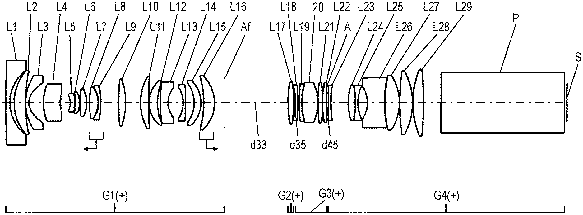
[0010] FIG. 1 shows a placement of lenses at a wide angle end, where an infinity focus state is achieved, of the imaging optical system in accordance with the first embodiment.
[0011] FIG. 2 shows a placement of lenses at a wide angle end for indicating a light path of the imaging optical system in accordance with the first embodiment.
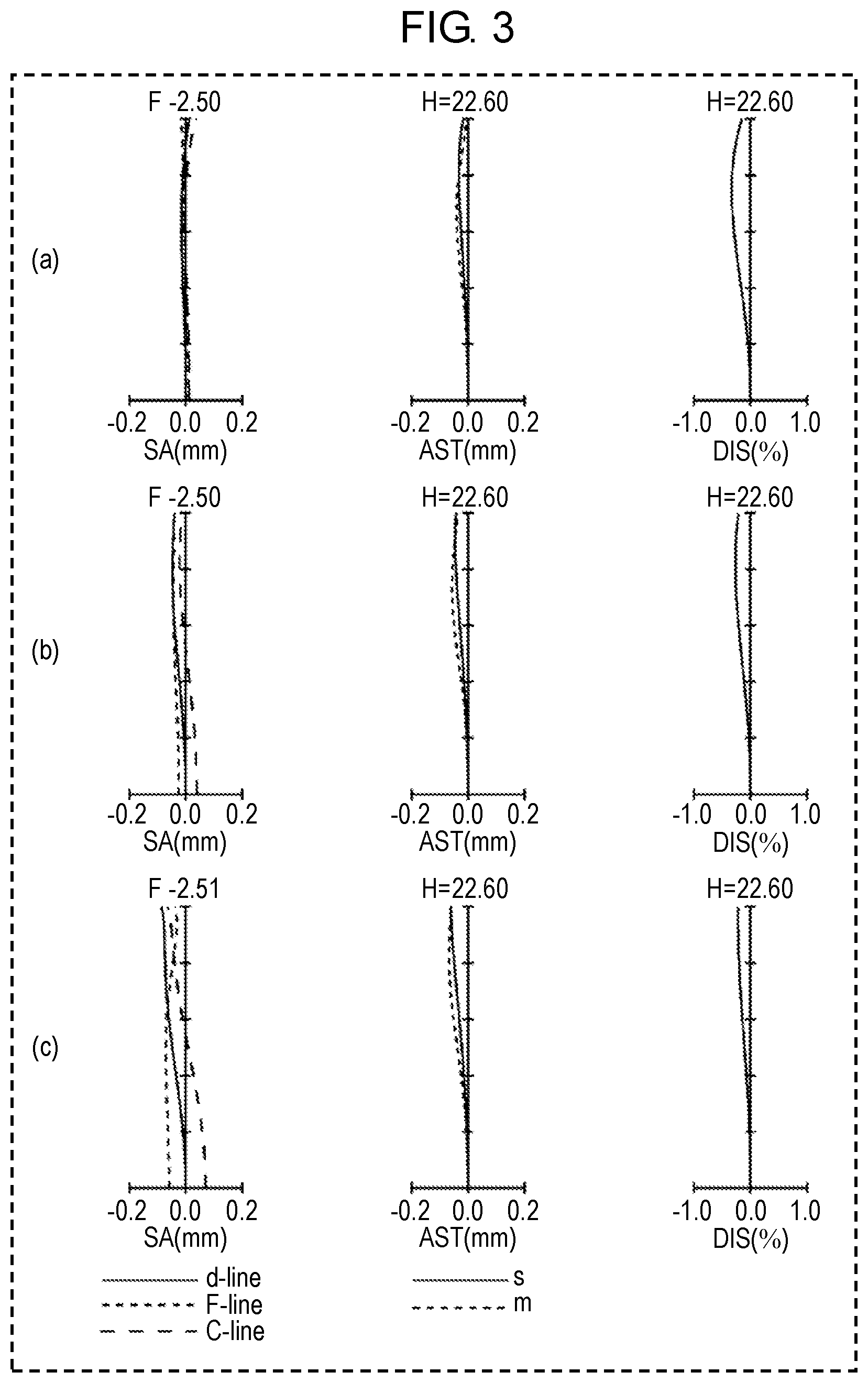
[0012] FIG. 3 shows longitudinal aberration diagrams each indicating that an object distance of the imaging optical system in accordance with the first embodiment is infinity.
[0013] FIG. 4 shows longitudinal aberration diagrams at a projection size of 200 inches of the imaging optical system in accordance with the first embodiment.
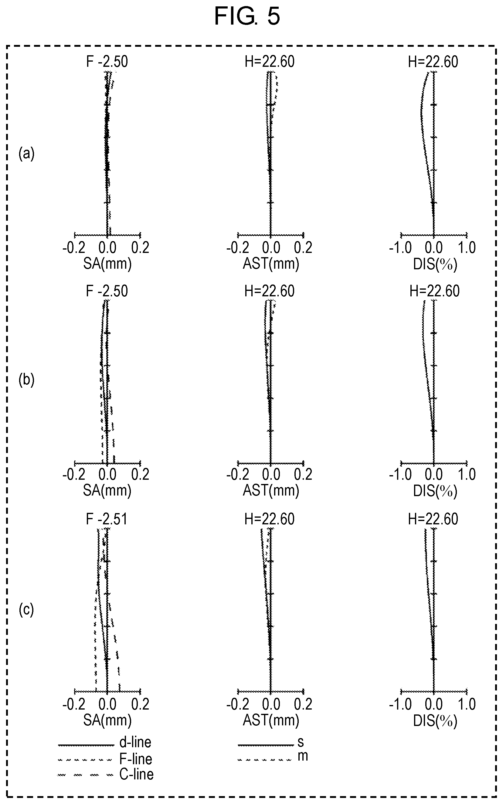
[0014] FIG. 5 shows longitudinal aberration diagrams at a projection size of 70 inches of the imaging optical system in accordance with the first embodiment.
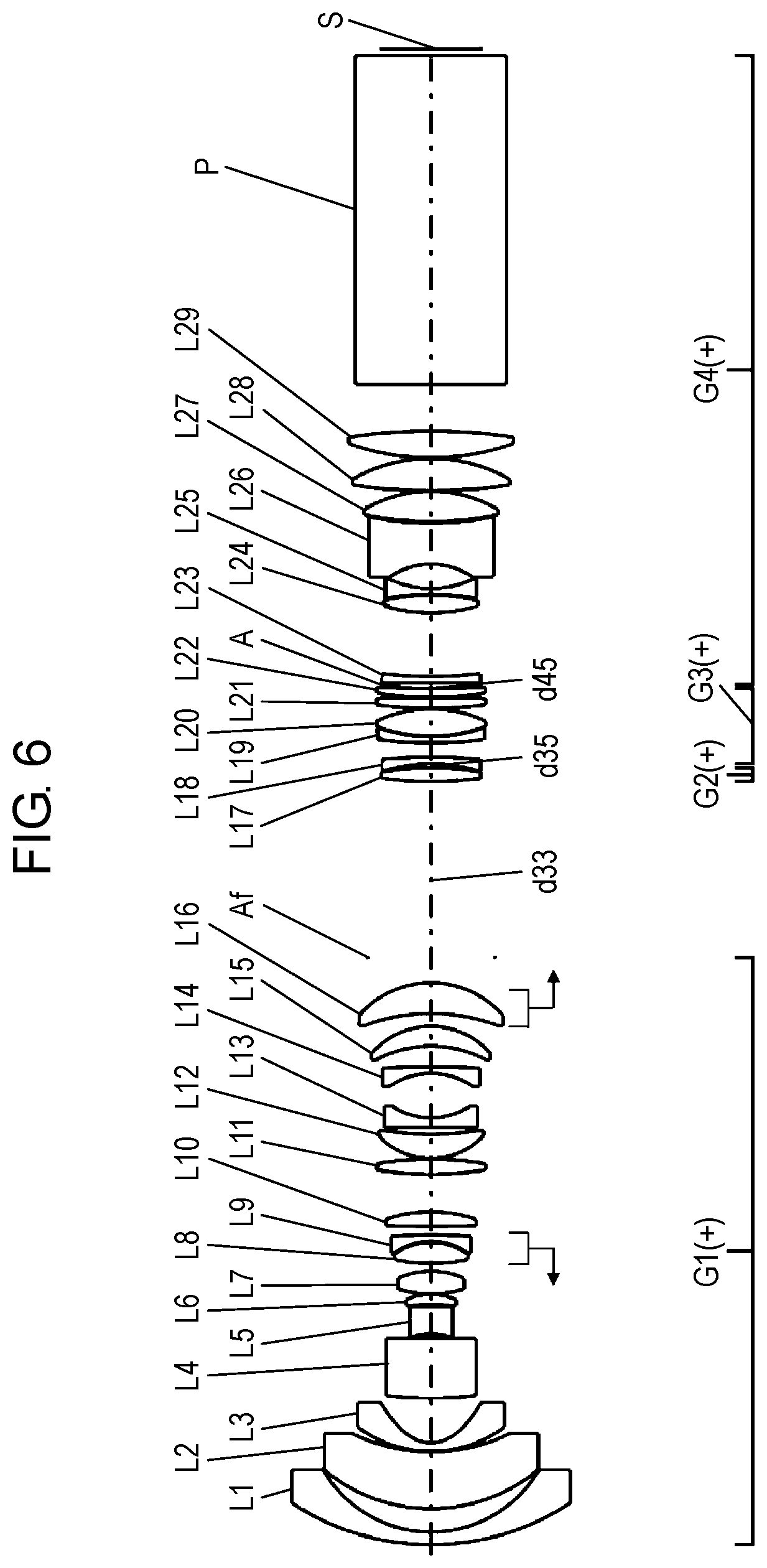
[0015] FIG. 6 shows a placement of lenses at a wide angle end, where an infinity focus state is achieved, of an imaging optical system in accordance with a second embodiment.
[0016] FIG. 7 shows a placement of lenses at a wide angle end for indicating a light path of the imaging optical system in accordance with the second embodiment.
[0017] FIG. 8 shows longitudinal aberration diagrams each indicating that an object distance of the imaging optical system in accordance with the second embodiment is infinity.
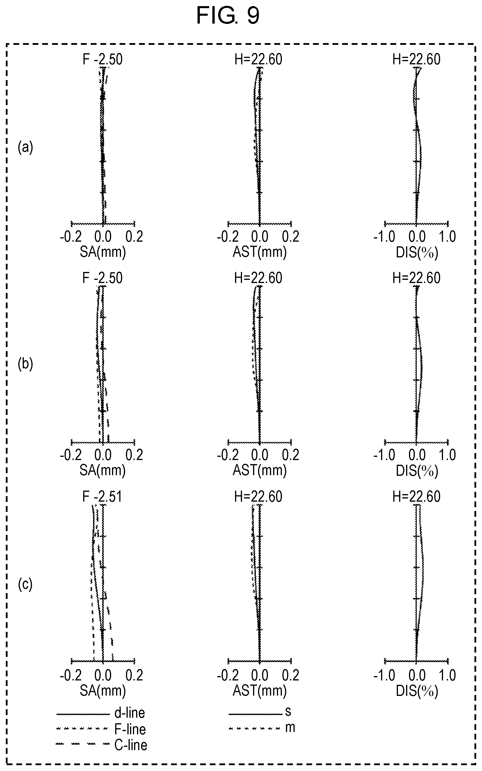
[0018] FIG. 9 shows longitudinal aberration diagrams at a projection size of 200 inches of the imaging optical system in accordance with the second embodiment.
[0019] FIG. 10 shows longitudinal aberration diagrams at a projection size of 70 inches of the imaging optical system in accordance with the second embodiment.
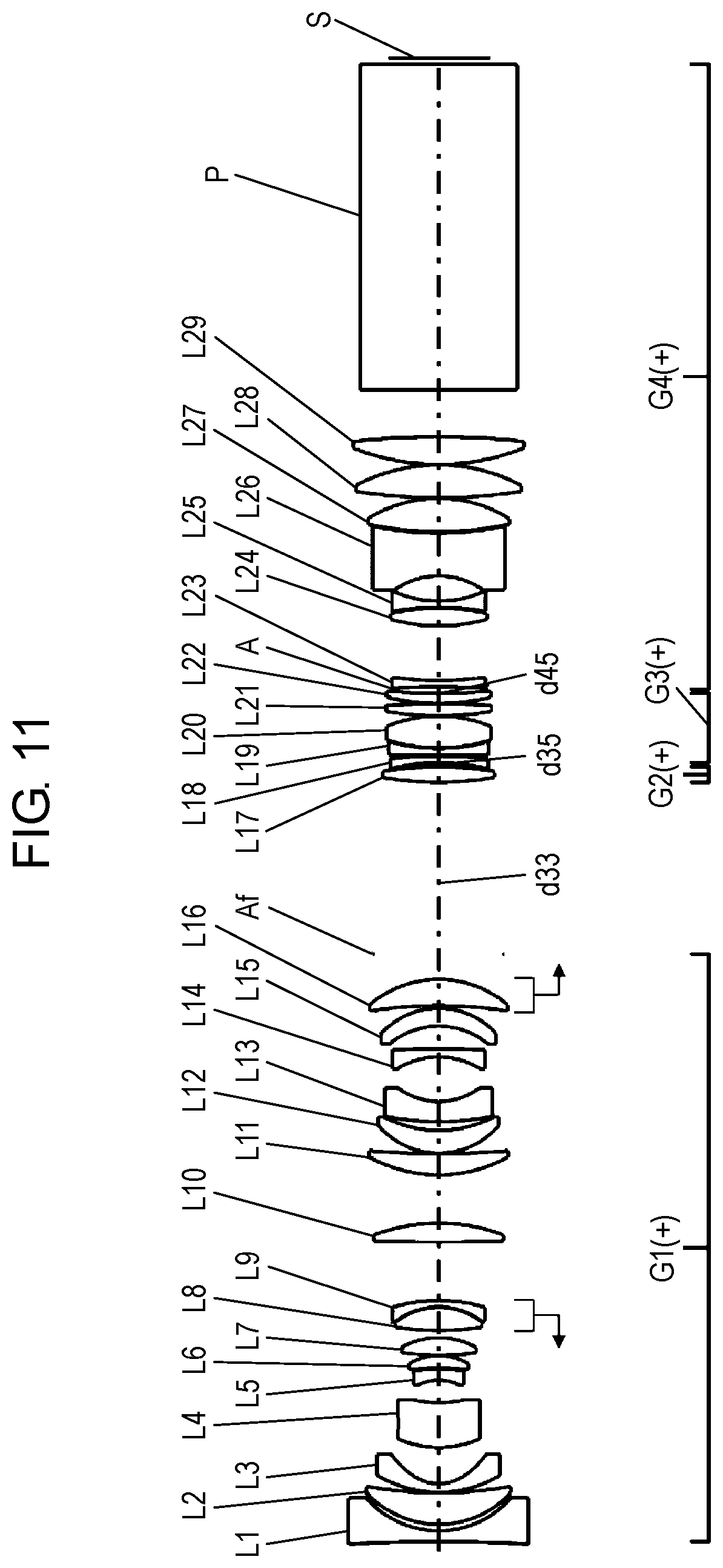
[0020] FIG. 11 shows a placement of lenses at a wide angle end, where an infinity focus state is achieved, of an imaging optical system in accordance with a third embodiment.
[0021] FIG. 12 shows a placement of lenses at a wide angle end for indicating a light path of the imaging optical system in accordance with the third embodiment.
[0022] FIG. 13 shows longitudinal aberration diagrams each indicating that an object distance of the imaging optical system in accordance with the third embodiment is infinity.
[0023] FIG. 14 shows longitudinal aberration diagrams at a projection size of 200 inches of the imaging optical system in accordance with the third embodiment.
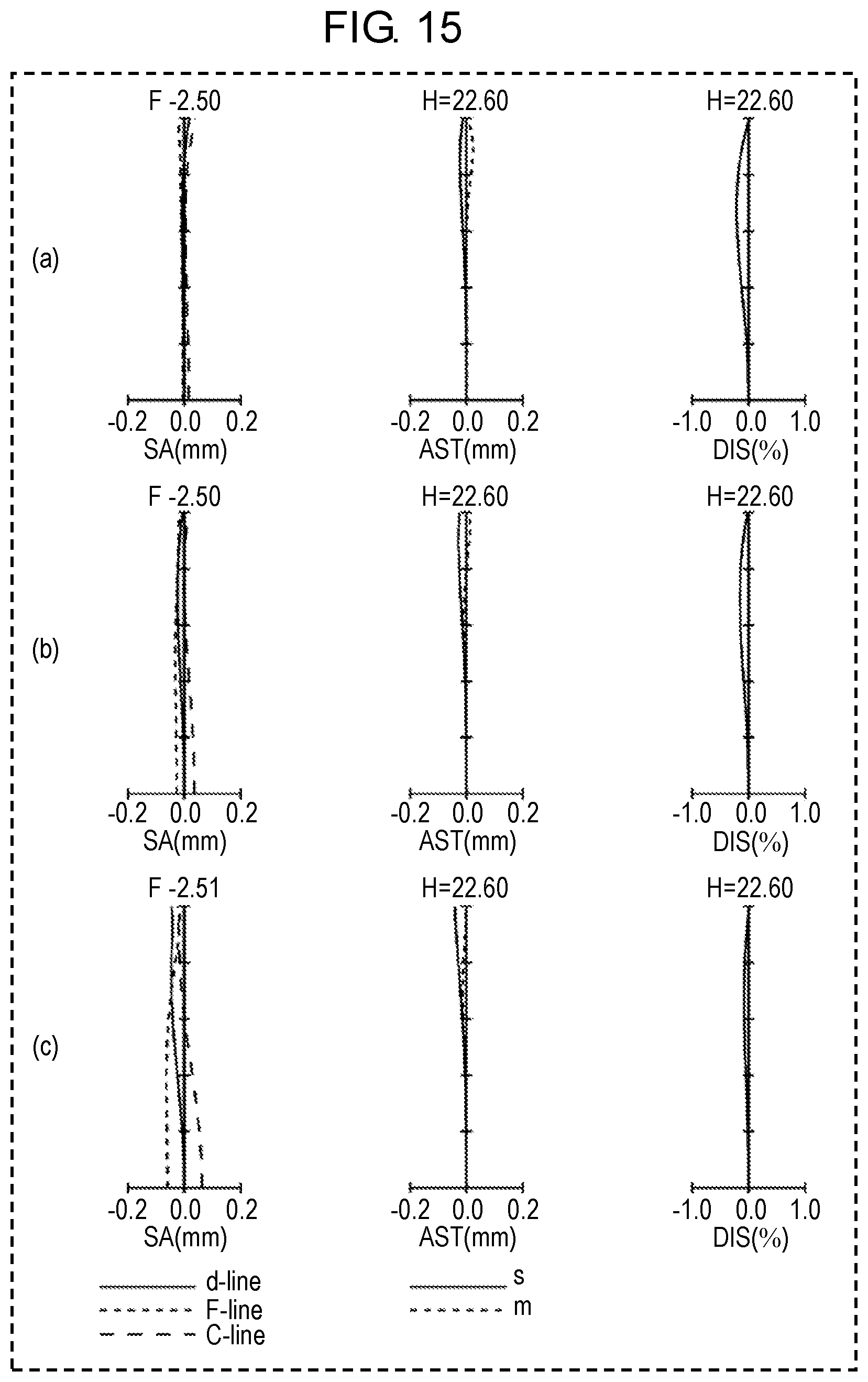
[0024] FIG. 15 shows longitudinal aberration diagrams at a projection size of 70 inches of the imaging optical system in accordance with the third embodiment.
DESCRIPTION OF EMBODIMENTS
[0025] The embodiments will be detailed hereinafter with reference to the accompanying drawings. Descriptions more than necessary will be omitted sometimes. For instance, detailed descriptions of well-known matters will be omitted, or duplicable descriptions about substantially the same structures will be omitted sometimes. These omissions will avoid redundancy in the descriptions and help ordinary skilled persons in the art understand the present disclosure with ease.
[0026] The accompanying drawings and the descriptions below are provided for the ordinary skilled persons in the art to fully understand the present disclosure, and not to mention, these materials do not intend to limit the scope of the claims.
[0027] FIG. 1 shows a placement of lenses of the imaging optical system in accordance with the first embodiment. FIG. 6 shows a placement of lenses of the imaging optical system in accordance with the second embodiment. FIG. 11 shows a placement of lenses of the imaging optical system in accordance with the third embodiment. In each one of these three drawings, unilateral arrows marked below the lens-groups indicate that the lens-group is a focusing lens group, and the directions of the arrows indicate a moving direction of the focusing lens group from the infinity focus state to the proximity focus state. The left side indicates a magnification side, and the right side indicates a reduction side. The mark of (+), or (-) indicates a positive power or a negative power of each one of the lens-groups. The straight line marked on the right-most side indicates a position of subject image S. The letter "P" at the left side of subject image S indicates an optical element including such as a color separation prism, color combining prism, optical filter, plane parallel glass, crystal low-pass filter, or infrared cut filter.
[0028] FIG. 2 is an optical sectional view illustrating a light path of the imaging optical system in accordance with the first embodiment. FIG. 7 is an optical sectional view illustrating a light path of the imaging optical system in accordance with the second embodiment. FIG. 12 is an optical sectional view illustrating a light path of the imaging optical system in accordance with the third embodiment. MI indicates an intermediate imaging position, and forms a boundary between the magnification side and the reduction side. Magnifying optical system Op is disposed on the magnification side from MI, and relay optical system OI is disposed on the reduction side from MI. Magnifying optical system Op conjugates a magnification conjugate point (projected image) on the magnification side and intermediate imaging position MI inside the imaging optical system. Relay optical system OI conjugates a reduction conjugate point (subject image S) on the reduction side and intermediate imaging position MI inside the imaging optical system.
[0029] FIG. 3 shows longitudinal aberration diagrams each indicating that an object distance of the imaging optical system in accordance with the first embodiment is infinity. FIG. 8 shows longitudinal aberration diagrams each indicating that an object distance of the imaging optical system in accordance with the second embodiment is infinity. FIG. 13 shows longitudinal aberration diagrams each indicating that an object distance of the imaging optical system in accordance with the third embodiment is infinity. The marks (a), (b), and (c) in each one of the diagrams indicate the aberration diagrams each of which focal length of the imaging optical system disclosed hero is on an wide angle end, on an intermediate position, and on a telephoto end. The wide angle end refers to a state of the shortest focal length, the intermediate stat refers to a state of an intermediate focal length, and the telephoto end refers to a state of the longest focal length. Assume that focal length in the shortest focal length state is fw, and that in the longest focal length state is fr, then the following equation (1) prescribes the focal length fm in the intermediate focal length state:
fm= {square root over ((f.sub.w*f.sub.r))} Equation (1)
[0030] FIG. 4 shows longitudinal aberration diagrams at a projection size of 200 inches (.times.145.1) of the imaging optical system in accordance with the first embodiment. FIG. 9 shows longitudinal aberration diagrams at a projection size of 200 inches (.times.145.1) of the imaging optical system in accordance with the second embodiment. FIG. 14 shows longitudinal aberration diagrams at a projection size of 200 inches (.times.145.1) of the imaging optical system in accordance with the third embodiment. The marks (a), (b), and (c) in each one of the diagrams indicate the aberration diagrams each of which focal length of the imaging optical system disclosed here is on an wide angle end, on an intermediate position, and on a telephoto end.
[0031] FIG. 5 shows longitudinal aberration diagrams at a projection size of 70 inches (.times.50.8) of the imaging optical system in accordance with the first embodiment. FIG. 10 shows longitudinal aberration diagrams at a projection size of 70 inches (.times.50.8) of the imaging optical system in accordance with the second embodiment. FIG. 15 shows longitudinal aberration diagrams at a projection size of 70 inches (.times.50.8) of the imaging optical system in accordance with the third embodiment. The marks (a), (b), and (c) in each one of the diagrams indicate the aberration diagrams each of which focal length of the imaging optical system disclosed here is on an wide angle end, on an intermediate position, and on a telephoto end.
[0032] Each one of the aberration diagrams includes a spherical aberration diagram, astigmatism diagram, and distortion diagram in this order from the left to the right. In the spherical aberration diagram, the lateral axis represents the spherical aberration (SA mm), and the vertical axis represents F-number (numbers marked with F in the diagrams). In the spherical aberration diagram, the solid line, broken line, and long-dash line represent the characteristics of d-line, F-line, and C-line respectively. In the astigmatism diagram, the lateral axis represents the astigmatism (AST mm), and the vertical axis represents an image height (marked with H). In the astigmatism diagram, the solid line shows the characteristics of sagittal plane (marked with s), the broken line shows the characteristics of meridional plane (marked with m). In the distortion diagram, the vertical axis represents a distortion (DIS %), and the vertical axis represents an image height (marked with II).
[0033] In the embodiments below, a subject image, formed by an image forming element including such as liquid crystal or DMD (Digital Micro-mirror Device), is projected onto a screen by a projector (image projection apparatus), and this projector employs the imaging optical system. The screen (not shown) lies on an extension line of the magnification side. The imaging optical system magnifies subject image S formed by a liquid crystal panel disposed on the reduction side, and projects it onto the screen.
[0034] The imaging optical system disclosed here includes first lens group G1 of positive power, second lens group G2 of positive power, third lens group G3 of positive power, and fourth lens group G4 of positive power in this order from the magnification side to the reduction side.
[0035] First lens group G1 is formed of first front-side sub-lens group G1f and first rear-side sub-lens group G1r. First lens group G1 is formed of 16 lenses numbered first lens L1 through sixteenth lens L16. First front-side sub-lens group C1f is formed of third lens L3, which is an aspherical lens and located furthest on the magnification side among other aspherical lenses, and other lenses located farther on the magnification side than lens L3. First rear-side sub-lens group G1r is formed of the lenses disposed toward the reduction side from aspherical third lens L3.
[0036] First lens group G1 includes the following lenses located from the magnification side toward the reduction side in this order:
[0037] negative first lens L1;
[0038] positive meniscus second lens L2 of which convex faces toward the magnification side;
[0039] negative meniscus third lens L3 of which convex faces toward the magnification side;
[0040] positive meniscus fourth lens L4 of which convex faces toward the magnification side;
[0041] negative fifth lens L5;
[0042] positive meniscus sixth lens L6 of which convex faces toward the reduction side;
[0043] biconvex seventh lens L7;
[0044] biconvex eighth lens L8;
[0045] negative meniscus ninth lens L9 of which convex faces toward the reduction side;
[0046] biconvex tenth lens L10;
[0047] positive eleventh lens L11;
[0048] positive meniscus twelfth lens L12 of which convex faces toward the magnification side;
[0049] negative thirteenth lens L13;
[0050] negative meniscus fourteenth lens L14 of which convex faces toward the reduction side;
[0051] positive meniscus fifteenth lens L15 of which convex faces toward the reduction side; and
[0052] positive meniscus sixteenth lens L16 of which convex faces toward the reduction side.
[0053] Third lens L3 has an aspherical surface on the reduction side, and on its magnification side there are first lens L1 of negative power and second lens L2 of positive power. A greater effective diameter of the aspherical lens invites greater difficulty in manufacturing the aspherical lens. In the imaging optical system of the present disclosure, the aspherical surface is formed on third lens L3, whereby the curvature of field as well as the distortion can be reduced. On top of that, second lens L2 located next to lens L3 on the magnification side has positive power, so that the effective diameter of the aspherical lens can be reduced. Sixteenth lens L16 has positive power and moves along the optical axis during the focusing action, viz. it forms a focusing lens group.
[0054] First lens group CG includes a field-curvature correction lens group formed of eighth lens L8 of positive power and ninth lens L9 of negative power. This correction lens group corrects a change in the field curvature, the change being incurred by the movements of each one of the lens groups during the focusing action. In this case, eighth lens L8 and ninth lens L9 move along the optical axis, and they can move toward the magnification side or the reduction side depending on a moving amount of the sixteenth lens L16 (i.e. focusing lens group) for focusing or a correction amount of the field curvature. Since the field curvature correction lens group is formed of one sheet of negative lens and one sheet of positive lens, this simple structure allows correcting the curvature of field as well as reducing a change in sensitivity of focusing.
[0055] Second lens group G2 is formed of biconvex seventeenth lens L17.
[0056] Third lens group G3 is formed of eighteenth lens L18 through twenty-second lens L22. Those lenses are located from the magnification side toward the reduction side in the following order:
[0057] negative meniscus eighteenth lens 18 of which convex faces toward the reduction side;
[0058] negative nineteenth lens L19;
[0059] biconvex twentieth lens L20;
[0060] biconvex twenty-first lens L21; and
[0061] positive meniscus twenty-second lens L22 of which convex faces toward the magnification side.
Between sixteenth lens L16 and seventeenth lens L17, flare-cut aperture Af is placed.
[0062] Fourth lens group G4 is formed of aperture A, twenty-third lens L23 through twenty-ninth lens L29, and prism P. Those members are disposed from the magnification side toward the reduction side in the following order: biconcave lens L23;
[0063] biconvex lens L24;
[0064] biconcave lens L25;
[0065] biconcave lens L26;
[0066] biconvex lens L27;
[0067] biconvex lens L28;
[0068] biconvex lens L29; and
[0069] prism P.
[0070] Fifth lens L5 desirably has the specifications below: [0071] High transmittance, Abbe number <30, and absorption coefficient <0.008 at a wavelength of 400 nm of transmitted light. This absorption coefficient can be found from the following expression:
[0071] -1/t.times.ln(I/I.sub.0)
where, t is a travel distance of light through the lens, I.sub.O is an intensity of the light before it enters the lens, and I is an intensity of the light after it travels by distance t.
[0072] First lens L1 and third lens L3, both are of negative power, disposed on the magnification side of fifth lens L5 desirably have the following specifications: [0073] Abbe number .gtoreq.30, or [0074] Absorption coefficient .gtoreq.0.008 at the wavelength=400 nm of transmitted light.
[0075] When the imaging optical system zooms from the wide angle end to the telephoto end, first lens group G1 is fixed relatively to an image surface of subject image S. Second lens group G2 simply moves toward the magnification side with respect to the image surface of subject image S. Third lens group G3 simply moves toward the magnification side with respect to the image surface of subject image S. Fourth lens group G4 is fixed relatively to the image surface of subject image S.
[0076] Then an intermediate image is formed at intermediate imaging position MI within first lens group G1. To be more specific, intermediate imaging position MI is located between thirteenth lines L13 and fourteenth lens L14. First lens group G1 carries out two actions here, viz. an action of a field lens for guiding marginal rays toward the reduction side before and after the intermediate imaging, and an action of a projection lens.
[0077] The imaging optical system in accordance with the present embodiment includes multiple lens-groups each having at least one lens. During a zooming action, the lens-groups move such that spaces between each one of the groups change. The imaging optical system conjugates a conjugate point on the magnification side and an intermediate imaging position inside the imaging optical system. The imaging optical system conjugates a conjugate point on the reduction side and the intermediate imaging position inside the imaging optical system. The imaging optical system includes the first lens group and a rear lens group in this order from the magnification side toward the reduction side. The first lens group is located furthest on the magnification side, and includes a field curvature correction lens group and a focusing lens group. The field curvature correction lens group moves along the optical axis for correcting an amount of field curvature. The focusing lens group moves along the optical axis during an action of focusing from an infinite focus state to a proximate focus state. The conditions that should be satisfied by the imaging optical system are introduced below:
[0078] First lens group G 1 of the imaging optical system in accordance with the present disclosure satisfies the condition (1) below:
1.5<f1b/f1<4.0 (1)
where, fib is a focal length of first rearside sub-lens group located farther on the reduction side than the aspherical lens located furthest on the magnification side in the first lens group,
[0079] f1 is a focal length of the first lens group.
[0080] Condition (1) prescribes the relation between first rearside sub-lens group G1r and first lens group G1, where sub-lens group G1r is located farther on the reduction side than the aspherical lens located furthest on the magnification side in first lens group G1. Satisfaction of condition (1) will invite this advantage: correcting the field curvature and the distortion easily with the effective diameter of aspherical third lens L3 being reduced. Falling below the lower limit of condition (1) allows the first rearside sub-lens group G1r located farther on the reduction side than third lens L3 to exert excessively strong power (greater refracting power), so that the corrections of the field curvature and the distortion become difficult. To the contrary, excess over the upper limit of condition (1) allows the first rearside sub-lens group G1r located farther on the reduction side than aspherical third lens L3 of first lens group G1 to exert extremely weak power, so that the effective diameter of aspherical third lens L3 adjacent to first rearside sub-lens group G1r becomes greater, which adversely invites a higher manufacturing cost.
[0081] Satisfaction of condition (1a) below more positively achieves the advantage discussed above.
2.0<f1b/f1<3.5 (1a)
The imaging optical system satisfies the condition (2) below.
0.01<|d/fw|<1.50 (2)
where, d is a space on the optical axis between the lens of negative power and the lens of positive power located farther on the magnification side than the aspherical lens located furthest on the magnification side in the first lens group, and
[0082] fw is a focal length of the total system at the wide angle end.
[0083] Condition (2) prescribes the spaces between each one of the lenses located farther on the magnification side than the aspherical lens of first lens group G1. Satisfaction of condition (2) will invite this advantage: reducing the effective diameters of the aspherical lens and other lenses located farther on the magnification side than the aspherical lens while the field curvature and the distortion are corrected improvingly. Falling below the lower limit of condition (2) will make a space too short between the negative lens and the positive lens located farther on the magnification side than the aspherical lens, so that the filed curvature and the distortion cannot be corrected sufficiently. To the contrary, excess over an upper limit of condition (2) will invite adversely a greater effective diameter of the aspherical lenses and other lenses located farther on the magnification side.
[0084] On top of that, satisfaction of condition (2a) below more positively achieves the foregoing advantage.
0.05<|d/fw|<1.00 (2a)
The imaging optical system in accordance with the present disclosure satisfies the condition (3) below:
0.5<(R1f+R1r)/(R1f-R1r)<5.0 (3)
where, R1f is a curvature radius of the surface, facing the magnification side, of the spherical lens of negative power located farther on the magnification side than the aspherical lens located furthest, among other aspherical lenses, on the magnification side, and
[0085] R1r is a curvature radius of the surface, facing the reduction side, of the spherical lens of negative power located farther on the magnification side than the aspherical lens located furthest, among other aspherical lenses, on the magnification side.
[0086] Condition (3) prescribes a shaping factor of the spherical lenses of negative power located farther on the magnification side than the aspherical lens. Satisfaction of condition (3) will invite this advantage: reducing the effective diameters of the lenses while the field curvature and the distortion can be corrected. Falling below the lower limit of condition (3) will invite an insufficient correction of the field curvature and the distortion. To the contrary, excess of the upper limit of condition (3) will invite adversely greater effective diameters of the lenses located farther on the magnification side than the aspherical lens.
[0087] Satisfaction of condition (3a) below more positively achieves the foregoing advantage.
0.7<(R1f+R1r)/(R1f-R1r)<3.5 (3a)
[0088] The imaging optical system of the present disclosure satisfies condition (4) below:
|{(1-.beta.cw.sup.2).times..beta.crw.sup.2)}/{(1-.beta.fw.sup.2).times..- beta.frw.sup.2}|<0.2 (4)
where, .beta.cw is a paraxial lateral magnification, at a wide angle end, of a field curvature correction lens-group moving along the optical axis in the case of an amount of field curvature being changed.
[0089] .beta.crw is a paraxial lateral magnification, at the wide angle end, of each of the lenses located farther on the reduction side than the field curvature correction lens-group moving along the optical axis in the case of the amount of the field curvature being changed, .beta.fw is a paraxial lateral magnification, at the wide angle end, of the focusing lens-group moving along the optical axis during the focusing action, and
[0090] .beta.frw is a paraxial lateral magnification, at the wide angle end, of every lens located farther on the reduction side than the focusing lens-group moving along the optical axis during the focusing action.
[0091] Condition (4) relates to focusing sensitivities of the field curvature lens group and the focusing lens group. Satisfaction of condition (4) will invite this advantage: preventing the focus from being out of focus even if the field curvature correction lens-group is moved during the adjustment of an amount of field curvature. Excess over an upper limit of condition (4) will invite an out-of-focus when the field curvature correction lens-group is moved, so that the correction of the field curvature and the focusing become difficult.
[0092] Satisfaction of condition (4a) below more positively achieves the foregoing advantage.
|{(1-.beta.cw.sup.2).times..beta.crw.sup.2}/{(1-.beta.fw.sup.2).times..b- eta.frw.sup.2}|<0.15 (4a)
The imaging optical system of the present disclosure satisfies condition (5) below:
|ff/fc|<0.8 (5)
where, ff is a focal length of the focusing lens group moving along the optical axis during the focusing action, and
[0093] fc is a focal length of the field curvature correction lens-group moving along the optical axis when an amount of the field curvature is changed.
[0094] Condition (5) prescribes the focal length of the field curvature correction lens-group with respect to the focal length of the focusing lens group. Satisfaction of condition (5) will invite this advantage: weakening influence of the field curvature correction lens-group to the focusing sensitivity. Excess over an upper limit of condition (5) will adversely invite stronger power of the field curvature correction lens-group, so that the focus becomes out of focus when the field curvature correction lens-group is moved.
[0095] Satisfaction of condition (5a) below more positively achieves the foregoing advantage.
|ff/fc|<0.6 (5a)
First lens group G1 satisfies condition (6) below:
|fc/f1|<0.3 (6)
where, f1 is a focal length of first lens group G1
[0096] Condition (6) prescribes the focal length of the field curvature correction lens-group with respect to the focal length of first lens group G1. Satisfaction of condition (6) will invite this advantage: reducing a change in the focus position with respect to an amount of movement of the field curvature correction lens-group, so that an out-of-focus can be prevented even if the field curvature correction lens-group moves for correcting the field curvature. Excess over an upper limit of condition (6) will invite an out-of-focus when the correction lens-group moves, so that the correction of the field curvature as well as an adjustment of focus becomes difficult.
[0097] Satisfaction of condition (6a) below more positively achieves the foregoing advantage.
|fc/f1|<0.2 (6a)
The imaging optical system of the present disclosure satisfies condition (7) below:
3.0<f1/fp<15.0 (7)
where, f1 is a composite focal length at a wide angle end of a relay optical system located farther on the reduction side than the intermediate imaging position, and
[0098] fp is a composite focal length at a wide angle end of a relay optical system located farther on the magnification side than the intermediate imaging position.
[0099] Condition (7) prescribes a magnifying optical system and the relay optical system. Satisfaction of condition (7) will invite this advantage: lowering various aberrations in the imaging optical system as well as downsizing the same system. Falling below a lower limit of condition (7) will invite a difficulty in generally parallelizing a chief ray and other rays given off from a surface of the image on the reduction side. Excess over an upper limit of condition (7) will adversely invite a difficulty in reducing effective diameters of the lenses located on the magnification side.
[0100] Satisfaction of condition (7a) below more positively achieves the foregoing advantage.
4.0<f1/fp<12.0 (7a)
The imaging optical system of the present disclosure satisfies condition (8) below:
2.0<|f4/ft|<10.0 (8)
where, f4 is a focal length of the fourth lens group; and
[0101] ft is a focal length of the total system at the telephoto end.
[0102] Condition (8) prescribes the power of fourth lens group G4. Satisfaction of condition (8) will invite this advantage: shortening the total length while the light given off from the image surface on the reduction side and deviated from the optical axis can be generally parallelized to the optical axis. Falling below a lower limit of condition (8) will make it impossible to parallelize a chief ray of the light deviated from the optical axis with the optical axis. Excess over an upper limit of condition (8) will invite a difficulty in shortening the total length.
[0103] Satisfaction of condition (8a) below more positively achieves the foregoing advantage.
3.0<|f4/ft|<6.5 (8a)
The imaging optical system of the present disclosure satisfies condition (9) below:
0.4<f4/bf<1.0 (9)
where, bf is a distance from a lens surface located furthest on the reduction side to an image surface on the reduction side.
[0104] Condition (9) prescribes a back focus. Satisfaction of condition (9) will invite this advantage: shortening the total length while the chief ray of the light deviated from the optical axis and given off from the image surface on the reduction side can be parallelized with the optical axis. Falling below a lower limit of condition (9) will lengthen the back focus, so that the shortening of the total length becomes difficult. Excess over an upper limit of condition (9) will make it impossible to parallelize the chief ray of the light, deviated from the optical axis and given off the image surface on the reduction side, with the optical axis.
[0105] Satisfaction of condition (9a) below more positively achieves the foregoing advantage.
0.55<f4/bf<0.8 (9a)
The imaging optical system of the present disclosure satisfies condition (10) below:
.PHI.ht/.PHI.s<0.9 (10)
where, .PHI.ht is an effective diameter of the lens having the following specifications:
[0106] Abbe number <30, and light absorption coefficient of the light having 400 nm wavelength <0.008,
[0107] .PHI.s is an aperture diameter of aperture stop.
[0108] Condition (10) prescribes the lenses of which effective diameters are smaller than an aperture diameter. Satisfaction of condition (10) will invite this advantage: preventing the lenses located near to an entrance pupil and having the smaller effective diameters from being affected by a temperature rise due to condensed light. Excess over an upper limit of condition (10) will invite a greater effective diameter of the lenses, and increase the cost thereof.
[0109] Satisfaction of condition (10a) below more positively achieves the foregoing advantage.
.PHI.ht/.PHI.s<0.6 (10a)
The imaging optical system of the present disclosure satisfies condition (11) below:
0.1<|fht/fw|<100.0 (11)
where, fht is a focal length of a lens having a high transmittance.
[0110] Condition (11) prescribes a focal length of the lens having the following specification:
[0111] Abbe number <30, and
[0112] light absorption coefficient of the light having 400 nm wavelength <0.08. Satisfaction of condition (11) will invite this advantage: correcting a chromatic aberration excellently. Falling below a lower limit of condition (11) will lower the correction effect of the chromatic aberration, and excess over an upper limit of condition (11) will invite frequent occurrences of the chromatic aberration.
[0113] Satisfaction of condition (11a) below more positively achieves the foregoing advantage.
0.8<|fht/fw|<50.0 (11a)
[0114] As discussed above, the embodiment is demonstrated hereinbefore as an example of the techniques disclosed in the present patent application.
[0115] Nevertheless, the techniques of the present disclosure are not limited to the foregoing example, but are applicable to other embodiments in which changes, replacements, additions, or omissions are carried out appropriately.
[0116] Embodiments 1-3 of the imaging optical system with numerical simulations are demonstrated hereinafter. In each one of the numerical simulations, a unit of length is expressed in mm (millimeter), a unit of angle of view is expressed in .degree. (degree). In each one of the numerical simulations, the following abbreviations are used:
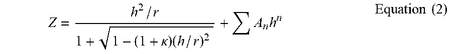
r=curvature radius, d=face-to-face dimension, nd=refractive index with respect to d line, and vd=Abbe number with respect to d line. In each one of the numerical simulations, the face marked with * is an aspherical face, and its shape is defined with the following equation (2).
Z = h 2 / r 1 + 1 - ( 1 + .kappa. ) ( h / r ) 2 + A n h n Equation ( 2 ) ##EQU00001##
where, Z is a distance from a point on an aspherical face, located above the optical axis with a height h, to the tangent plane at the vertex of the aspherical face;
[0117] h is a height from the optical axis;
[0118] r is curvature radius at the vertex;
[0119] .kappa. is a cone constant; and
[0120] An is a nth aspherical coefficient
First Embodiment with Numerical Simulation
[0121] A throw ratio of the imaging optical system in accordance with the first embodiment is 0.7 at the wide angle end and 0.9 at the telephoto end. The throw ratio is found by this formula: projecting distance/lateral size of an image projected on a screen, where the projecting distance measures from a lens surface located furthest on the magnification side (closest to the screen) of the imaging optical system to the screen along the projecting direction.
[0122] The image height used in the following data is set equal to or greater than 17.5 mm which is a diagonal dimension of the image forming element, because the design is drawn on the assumption that the optical axis of the imaging optical system can be shifted with respect to the image forming element.
[0123] Tables 1-10 show the lens data used in this first embodiment. Tables 2 and 3 list a series of surface data. The diameter of the aperture stop is 43. 318 mm.
TABLE-US-00001 TABLE 1 Focal length of lens/ Absorption Focal coefficient Effective length @400 diameter/ Focal of wide Lens glass .alpha. = -(1/t) Effective Aperture length angle material *ln(l/10) diameter diameter of lens end L1 EFL6 0.0041 106.496 2.46 -92.02 4.19 L2 TAF3 0.0030 80.392 1.86 105.60 4.81 L3 KPBK40 0.0009 68.002 1.57 -55.66 2.54 L4 PBH56 0.0039 46.430 1.07 303.34 13.82 L5 PBH56 0.0039 22.078 0.51 -31.56 1.44 L6 TAC8 0.0015 26.224 0.61 53.72 2.45 L7 FCD100 0.0003 34.094 0.79 61.15 2.78 L8 FCD100 0.0003 38.568 0.89 61.43 2.80 L9 P8H56 0.0039 41.198 0.96 -59.58 2.71 L10 FCD1 0.0005 57.492 1.33 149.41 6.81 L11 FDS90SG 0.0192 63.794 1.47 87.88 4.00 L12 FDS90SG 0.0192 55.060 1.27 79.06 3.60 L13 TAFD25 0.0158 50.298 1.16 -44.37 2.02 L14 FDS90SG 0.0192 45.098 1.04 -47.29 2.15 L15 FD140 0.0208 55.768 1.29 253.23 11.53 L16 FDS90SG 0.0192 68.456 1.58 81.94 3.73 L17 FC5 0.0002 51.540 1.19 161.72 7.37 L18 TAFD25 0.0158 43.758 1.01 -126.82 5.78 L19 NBFD15 0.0090 45.244 1.04 -129.39 5.89 L20 FCD100 0.0003 48.940 1.13 86.39 3.93 L21 FCD1 0.0005 49.420 1.14 263.82 12.02 L22 FC5 0.0002 48.884 1.13 312.22 14.22 L23 NBF1 0.0016 43.180 1.00 -154.18 7.02 L24 PBH56 0.0039 44.224 1.02 50.58 2.30 L25 BACD18 0.0013 42.770 0.99 -55.25 2.52 L26 EFD2 0.0057 61.660 1.42 -42.19 1.92 L27 FCD100 0.0003 67.598 1.56 106.28 4.84 L28 FCD100 0.0003 79.724 1.84 146.59 6.68 L29 FCD100 0.0003 83.052 1.92 192.94 8.79 P NBK7 0.0003 75.552 1.74 .infin. .infin.
TABLE-US-00002 TABLE 2 Surface data Effective Surface number r d nd vd radius Object surface .infin. 1 1566.213 5 1.56732 42.8 53.248 2 50.4642 5.2599 40.3 3 60.3617 14.264 1.8042 46.5 40.196 4 186.7145 0.2 38.752 5 62.3334 4 1.5176 63.5 34.001 6* 19.2718 18.3912 25.523 7 69.2944 21 1.84139 24.6 23.215 8 81.9474 12.4326 15.262 9 -23.122 4.9867 1.84139 24.6 9.102 10 -196.311 1.0239 11.039 11 -79.0965 5.5792 1.72916 54.7 11.372 12 -26.9757 0.2 13.112 13 91.423 8.6607 1.437 95.1 16.122 14 -36.6678 3.5 17.047 15 120.8847 10.5867 1.437 95.1 18.994 16 -33.5863 0.5438 19.284 17 -33.2628 3 1.84139 24.6 19.188 18 -102.948 22.0847 20.749 19 371.5186 8.6914 1.497 81.6 28.22 20 -92.0884 18.705 28.746 21 67.6708 10.283 1.84666 23.8 31.897 22 695.7607 0.2 31.337 23 36.4317 10.6602 1.84666 23.8 27.53 24 69.2215 3.3563 25.605 25 155.025 9.9187 1.90366 31.3 25.149 26 30.8893 18.6872 18.885 27 -37.3495 3 1.84666 23.8 19.735 28 -576.499 10.649 22.549 29 -43.0978 8.6626 1.76182 26.6 24.784 30 -38.2896 3.3195 27.884 31 -122.818 13.4628 1.84666 23.8 33.082 32 -46.5597 12 34.228
TABLE-US-00003 TABLE 3 Surface data (continued) Effective Surface number r d nd vd radius Object surface .infin. 33 .infin. Variable 30.253 34 144.3081 7.2259 1.48749 70.4 25.77 35 -170.905 Variable 25.455 36 -100.506 3 1.90366 31.3 21.424 37 -828.752 1.8955 21.879 38 484.9338 3 1.8061 33.3 22.283 39 85.6041 0.2 22.622 40 81.097 19.643 1.437 95.1 22.779 41 -65.4274 0.2 24.47 42 182.2892 5.3394 1.497 81.6 24.71 43 -462.549 0.2 24.645 44 116.1663 4.999 1.48749 70.4 24.442 45 483.7295 Variable 24.112 46(Aperture) .infin. 0.7496 21.659 47 -933.889 3 1.7433 49.2 21.59 48 130.809 21.5887 21.245 49 70.684 8.9114 1.84139 24.6 22.112 50 -100.786 0.2 21.791 51 -138.501 3 1.63854 55.4 21.385 52 47.7388 12.0688 19.89 53 -35.9132 21 1.64769 33.8 20.138 54 140.5798 0.8751 30.83 55 163.1947 17.9493 1.437 95.1 31.389 56 -62.7453 0.2 33.799 57 265.2442 16.1256 1.437 95.1 39.196 58 -82.8947 0.2 39.862 59 107.2858 13.6246 1.437 95.1 41.526 60 -378.576 22 41.326 61 .infin. 153.8 1.5168 64.2 37.776 62 .infin. 3 23.048 Image surface .infin.
TABLE-US-00004 TABLE 4 Aspheric data Sixth surface K -9.80E-01 A4 3.86E-06 A6 -5.26E-10 A8 -1.89E-12 A10 -3.41E-15
TABLE-US-00005 TABLE 5 Various data when the projecting distance is infinity Zoom ratio: 1.28091 Wide angle Intermediate Telephoto Focal length -21.956 -24.7178 -28.1237 F-number -2.50403 -2.50346 -2.50738 Angle of view -45.8706 -42.4981 -38.8464 Image height 22.6 22.6 22.6 d33 79.6946 64.1547 47.8148 d35 2 10.6202 17.6792 d45 2 8.9196 18.2005
TABLE-US-00006 TABLE 6 Zoom lens groups' data Groups Start surface Focal length 1 1 49.16019 2 34 161.7153 3 36 170.849 4 46 111.0949
TABLE-US-00007 TABLE 7 Various data at projection size of 200 inches (145.1 times) Zoom ratio: 1.28078 Wide angle Intermediate Telephoto Focal length -21.9822 -24.7327 -28.1545 F-number -2.5039 -2.50364 -2.50718 Angle of view -45.8361 -42.4934 -38.8176 Image height 22.6 22.6 22.6 d0 3151.354 3550.512 4046.908 d14 3.211 3.034 3.2411 d18 22.3737 22.5507 22.3436 d30 3.4543 3.3805 3.424 d33 79.5598 64.0937 47.7103 d35 2 10.6202 17.6792 d45 2 8.9196 18.2005
TABLE-US-00008 TABLE 8 Zoom lens groups' data Groups Start surface Focal length 1 1 96.36227 2 15 -7888.86 3 19 52.9806 4 31 81.9355 5 34 161.7153 6 36 170.849 7 46 111.0949
TABLE-US-00009 TABLE 9 Various data at projection size of 70 inches (50.8 times) Zoom ratio: 1.28057 Wide angle Intermediate Telephoto Focal length -22.0305 -24.7842 -28.2116 F-number -2.50364 -2.50337 -2.50681 Angle of view -45.7727 -42.4368 -38.7637 Image height 22.6 22.6 22.6 d0 1079.914 1219.598 1393.301 d14 2.6681 2.5284 2.7802 d18 22.9166 23.0563 22.8045 d30 3.7029 3.6023 3.6185 d33 79.3112 63.8719 47.5158 d35 2 10.6202 17.6792 d45 2 8.9196 18.2005
TABLE-US-00010 TABLE 10 Zoom lens groups' data Groups Start surface Focal length 1 1 96.36227 2 15 -7888.86 3 19 52.9806 4 31 81.9355 5 34 161.7153 6 36 170.849 7 46 111.0949
Second Embodiment with Numerical Simulation
[0124] The throw ratio of the imaging optical system used in the second embodiment is 0.5 at the wide angle end, and 0.6 at the telephoto end.
[0125] Tables 11-20 show the lens data used in this second embodiment. Tables 12 and 13 list a series of surface data. The diameter of the aperture stop is 45. 444 mm.
TABLE-US-00011 TABLE 11 Focal length of lens/ Absorption Focal coefficient Effective length @400 diameter/ Focal of wide Lens glass .alpha. = -(1/t) Effective Aperture length angle material *ln(l/10) diameter diameter of lens end L1 TAF3 0.0030 130.000 2.86 -150.25 9.52 L2 TAFD55 0.0289 99.500 2.19 347.57 22.03 L3 LBAL42 0.0005 68.000 1.50 -39.67 2.51 L4 PBH56 0.0039 41.606 0.92 163.65 10.37 L5 PBH56 0.0039 20.700 0.46 -28.25 1.79 L6 TAC8 0.0015 24.110 0.53 52.68 3.34 L7 FCD100 0.0003 29.748 0.65 52.20 3.31 L8 FCD100 0.0003 35.630 0.78 51.53 3.27 L9 PBH56 0.0039 36.422 0.80 -39.74 2.52 L10 FCD1 0.0005 43.638 0.96 123.59 7.83 L11 FDS90SG 0.0192 50.958 1.12 90.09 5.71 L12 FDS90SG 0.0192 48.080 1.06 48.55 3.08 L13 NBFD13 0.0066 42.934 0.94 -41.48 2.63 L14 FDS90SG 0.0192 44.714 0.98 -43.30 2.74 L15 TAFD35 0.0129 55.002 1.21 98.88 6.27 L16 EFD10 0.0159 66.944 1.47 108.62 6.88 L17 FCS 0.0002 51.674 1.14 171.53 10.87 L18 TAFD35 0.0129 50.432 1.11 -105.06 6.66 L19 TAF1 0.0017 51.232 1.13 -159.74 10.12 L20 FCD100 0.0003 51.670 1.14 78.08 4.95 L21 FCD1 0.0005 50.334 1.11 324.81 20.59 L22 FC5 0.0002 49.754 1.09 553.98 35.11 L23 NBF1 0.0016 46.598 1.03 -257.64 16.33 L24 PBH56 0.0039 44.904 0.99 52.45 3.32 L25 BACED5 0.0021 43.078 0.95 -53.36 3.38 L26 EFD2 0.0057 58.248 1.28 -40.61 2.57 L27 FCD100 0.0003 65.168 1.43 104.04 6.59 L28 FCD100 0.0003 77.274 1.70 134.21 8.51 L29 FCD100 0.0003 81.102 1.78 182.17 11.54 P NBK7 0.0003 73.952 1.63 .infin. .infin.
TABLE-US-00012 TABLE 12 Surface data Effective Surface number r d nd vd radius Object surface .infin. 1 118.3107 6 1.8042 46.5 65 2 58.4276 10.8776 50.078 3 77.9176 26.5758 2.001 29.1 49.75 4 83.2721 0.2 36.969 5 57.1273 4 1.58313 59.4 34 6* 16.0409 21.0418 23.42 7 194.9286 28 1.84139 24.6 20.803 8 -438.146 2.2008 10.244 9 -27.1956 12.3593 1.84139 24.6 9.732 10 227.7262 1.1456 10.35 11 -109.596 4.8425 1.72916 54.7 9.827 12 -28.9728 0.2 12.055 13 53.8677 10.6735 1.437 95.1 14.788 14 -37.1852 3.5 14.874 15 79.9752 9.8193 1.437 95.1 17.715 16 -30.1758 0.6027 17.815 17 -29.464 3 1.84139 24.6 17.659 18 -259.411 4.0739 18.211 19 749.8122 6.6666 1.497 81.6 21.233 20 -66.7077 17.5544 21.819 21 152.7199 7.2323 1.84666 23.8 25.466 22 -149.065 0.2 25.479 23 33.7104 11.4596 1.84666 23.8 24.04 24 158.1885 3.0257 22.63 25 -4504.14 4.5988 1.8061 40.7 21.467 26 33.7038 20.7922 17.749 27 -34.3854 3 1.84666 23.8 19.188 28 -576.499 9.7401 22.357 29 -54.6338 9.2866 1.91082 35.2 25.416 30 -36.7612 5.9771 27.501 31 -89.2723 14.3951 1.72825 28.3 31.666 32 -44.789 12 33.472
TABLE-US-00013 TABLE 13 Surface data (continued) Effective Surface number r d nd vd radius Object surface .infin. 33 .infin. Variable 29.135 34 206.6891 6.145 1.48749 70.4 22.871 35 -139.063 Variable 25.837 36 -71.7241 3 1.91082 35.2 21.769 37 -292.053 6.7329 25.216 38 208.8528 3 1.7725 49.6 24.222 39 77.0832 0.2 25.616 40 74.2605 12.7526 1.437 95.1 25.721 41 -59.8229 0.2 25.835 42 189.2688 4.9689 1.497 81.6 25.167 43 -1088.05 0.2 25.046 44 166.1841 4.1667 1.48749 70.4 24.877 45 428.5025 Variable 24.584 46(Aperture) .infin. 0.6779 22.722 47 -1443.38 3 1.7433 49.2 23.299 48 220.9991 29.6526 22.405 49 76.8369 8.3363 1.84139 24.6 22.452 50 -98.5493 0.2 22.114 51 -143.016 3 1.65844 50.9 21.539 52 46.9613 11.3479 18.989 53 -34.3436 19.1043 1.64769 33.8 20.385 54 136.908 0.8345 29.124 55 158.7202 14.1737 1.437 95.1 31.712 56 -61.99 0.2 32.584 57 258.816 15.1777 1.437 95.1 38.257 58 -74.4845 0.2 38.637 59 112.9 12.5797 1.437 95.1 40.551 60 -260.816 22 40.463 61 .infin. 153.8 1.5168 64.2 36.976 62 .infin. 3 23.014 Image surface .infin.
TABLE-US-00014 TABLE 14 Aspheric data Sixth surface K -7.11E-01 A4 -1.00E-06 A6 -5.25E-09 A8 2.48E-12 A10 -3.33E-14
TABLE-US-00015 TABLE 15 Various data when the projecting distance is infinity Zoom ratio: 1.19381 Wide angle Intermediate Telephoto Focal length -15.7791 -17.1001 -18.8374 F-number -2.5032 -2.50293 -2.50544 Angle of view -54.9671 -52.8069 -50.1085 Image height 22.6 22.6 22.6 d33 82.3079 71.207 58.2442 d35 2 7.0208 11.5349 d45 2 8.08 16.5286
TABLE-US-00016 TABLE 16 Zoom lens groups' data Groups Start surface Focal length 1 1 37.09378 2 34 171.52818 3 36 225.39504 4 46 115.74054
TABLE-US-00017 TABLE 17 Various data at projection size of 200 inches (145.1 times) Zoom ratio: 1.19383 Wide angle Intermediate Telephoto Focal length -15.782 -17.0983 -18.841 F-number -2.50301 -2.50288 -2.50513 Angle of view -55.0287 -52.8726 -50.1466 Image height 22.6 22.6 22.6 d0 2241.422 2432.517 2685.48 d14 3.1581 3.124 3.2117 d18 4.4157 4.4498 4.3621 d30 6.157 6.1005 6.1249 d33 82.128 71.0835 58.0964 d35 2 7.0208 11.5349 d45 2 8.08 16.5286
TABLE-US-00018 TABLE 18 Zoom lens groups' data Groups Start surface Focal length 1 1 39.98678 2 15 -216.188 3 19 48.74835 4 31 108.6161 5 34 171.5282 6 36 225.395 7 46 115.7405
TABLE-US-00019 TABLE 19 Various data at projection size of 70 inches (50.8 times) Zoom ratio: 1.19392 Wide angle Intermediate Telephoto Focal length -15.7865 -17.1036 -18.8478 F-number -2.50268 -2.50251 -2.5046 Angle of view -55.1443 -52.9658 -50.216 Image height 22.6 22.6 22.6 d0 752.5299 819.3999 907.9235 d14 2.5291 2.5419 2.6795 d18 5.0448 5.0319 4.8943 d30 6.4822 6.4041 6.4019 d33 81.8027 70.78 57.8195 d35 2 7.0208 11.5349 d45 2 8.08 16.5286
TABLE-US-00020 TABLE 20 Zoom lens groups' data Groups Start surface Focal length 1 1 39.98678 2 15 -216.188 3 19 48.74835 4 31 108.6161 5 34 171.5282 6 36 225.395 7 46 115.7405
Third Embodiment with Numerical Simulation
[0126] The throw ratio of the imaging optical system used in this third embodiment is 0.9 at the wide angle end, and 1.1 at the telephoto end.
[0127] Tables 21-30 show the lens data used in this third embodiment. Tables 22 and 23 list a series of surface data. The diameter of the aperture stop is 43. 570 mm.
TABLE-US-00021 TABLE 21 Focal length of lens/ Absorption Focal coefficient Effective length @400 diameter/ Focal of wide Lens glass .alpha. = -(1/t) Effective Aperture length angle material *ln(l/10) diameter diameter of lens end L1 EF5 0.0044 84.806 1.95 -70.15 2.50 L2 TAF3 0.0030 67.924 1.56 73.09 2.60 L3 KPMK30 0.0005 57.828 1.33 -59.86 2.13 L4 PBH56 0.0039 38.668 0.89 240.97 8.58 L5 PBH56 0.0039 23.060 0.53 -32.59 1.16 L6 LAC14 0.0011 27.124 0.62 57.97 2.06 L7 FCD100 0.0003 34.650 0.80 68.08 2.42 L8 FCD100 0.0003 39.888 0.92 64.10 2.28 L9 PBH56 0.0039 43.010 0.99 -73.84 2.63 L10 FCD1 0.0005 60.544 1.39 158.64 5.65 L11 FDS90SG 0.0192 65.088 1.49 95.28 3.39 L12 PBH56 0.0039 56.170 1.29 106.44 3.79 L13 NBFD15W 0.0059 50.034 1.15 -57.25 2.04 L14 PBH56 0.0039 43.172 0.99 -47.44 1.69 L15 PBH56 0.0039 53.488 1.23 423.30 15.06 L16 FDS90SG 0.0192 64.284 1.48 76.01 2.71 L17 FC5 0.0002 51.956 1.19 163.14 5.81 L18 NBFD15W 0.0059 45.428 1.04 -182.96 6.51 L19 NBFD15W 0.0059 46.192 1.06 -103.90 3.70 L20 FCD100 0.0003 48.506 1.11 86.05 3.06 L21 FCD1 0.0005 48.964 1.12 231.21 8.23 L22 FC5 0.0002 48.242 1.11 360.25 12.82 L23 NBF1 0.0016 43.430 1.00 -152.24 5.42 L24 PBH56 0.0039 45.022 1.03 55.18 1.96 L25 BACD18 0.0013 43.494 1.00 -59.96 2.13 L26 EF2 0.0049 62.506 1.43 -44.34 1.58 L27 FCD100 0.0003 66.422 1.52 105.00 3.74 L28 FCD100 0.0003 77.970 1.79 146.13 5.20 L29 FCD100 0.0003 81.078 1.86 194.35 6.92 P NBK7 0.0003 73.994 1.70 .infin. .infin.
TABLE-US-00022 TABLE 22 Surface data Effective Surface number r d nd vd radius Object surface .infin. 1 -656.064 5 1.60342 38 42.403 2 45.3758 3.068 34.002 3 46.5425 14.9135 1.8042 46.5 33.962 4 191.6049 0.2 32.662 5 56.5377 4 1.525 70.3 28.914 6* 19.7064 17.2085 22.414 7 49.4787 21 1.84139 24.6 19.334 8 52.7584 10.6396 11.929 9 -22.4814 5.0988 1.84139 24.6 9.521 10 -137.693 0.888 11.53 11 -82.5889 5.6684 1.6968 55.5 11.82 12 -27.8923 0.2 13.562 13 149.0052 8.2639 1.437 95.1 16.319 14 -36.5439 3.5 17.325 15 154.0886 10.8279 1.437 95.1 19.552 16 -33.5046 0.2 19.944 17 -33.8276 3 1.84139 24.6 19.901 18 -77.2754 27.5048 21.505 19 861.9723 8.9991 1.497 81.6 29.78 20 -86.4796 22.7441 30.272 21 67.6685 10.0365 1.84666 23.8 32.544 22 391.3697 0.2 31.909 23 37.4432 10.7465 1.84139 24.6 28.085 24 55.9061 4.1055 25.402 25 126.4832 9.5909 1.8061 33.3 25.017 26 32.6671 21.0051 18.789 27 -37.2255 3.6662 1.84139 24.6 19.101 28 -576.499 10.8649 21.586 29 -36.6964 8.4869 1.84139 24.6 23.23 30 -36.7843 1.2184 26.744 31 -203.449 12.3712 1.84666 23.8 31.221 32 -50.2529 12 32.142
TABLE-US-00023 TABLE 23 Surface data (continued) Effective Surface number r d nd vd radius Object surface .infin. 33 .infin. Variable 29.802 34 148.5076 7.2569 1.48749 70.4 25.978 35 -168.485 Variable 25.671 36 -94.9147 3 1.8061 33.3 22.523 37 -270.052 0.7616 22.714 38 -2984.09 3 1.8061 33.3 22.736 39 86.2081 0.2 23.096 40 81.2666 15.0258 1.437 95.1 23.262 41 -66.0493 0.2 24.253 42 154.4512 5.6237 1.497 81.6 24.482 43 -443.437 0.2 24.389 44 107.0246 4.7075 1.48749 70.4 24.121 45 270.0648 Variable 23.745 46(Aperture) .infin. 1.1545 21.785 47 -360.513 3 1.7433 49.2 21.715 48 165.5117 25.7366 21.436 49 86.5679 8.4491 1.84139 24.6 22.511 50 -95.6709 0.2 22.258 51 -146.607 3 1.63854 55.4 21.747 52 52.233 11.976 20.344 53 -35.9824 20.0137 1.62004 36.3 20.578 54 141.3419 0.8106 31.253 55 160.2086 15.7633 1.437 95.1 31.801 56 -62.38 0.2 33.211 57 258.7058 15.5491 1.437 95.1 38.335 58 -83.2405 0.2 38.985 59 108.6175 13.0242 1.437 95.1 40.539 60 -375.244 22 40.352 61 .infin. 153.8 1.5168 64.2 36.997 62 .infin. 3 23.022 Image surface .infin.
TABLE-US-00024 TABLE 24 Aspheric data Sixth surface K -9.73E-01 A4 3.64E-06 A6 -2.38E-11 A8 -5.60E-14 A10 -4.24E-16
TABLE-US-00025 TABLE 25 Various data when the projecting distance is infinity Zoom ratio: 1.21915 Wide angle Intermediate Telephoto Focal length -28.0988 -30.8792 -34.2567 F-number -2.50496 -2.50462 -2.50739 Angle of view -38.8107 -36.1987 -33.4064 Image height 22.6 22.6 22.6002 d33 80.9308 68.9152 56.1205 d35 2 8.4566 14.0857 d45 2 7.5589 14.7246
TABLE-US-00026 TABLE 26 Zoom lens groups' data Groups Start surface Focal length 1 1 59.1423 2 34 163.14226 3 36 173.85502 4 46 111.97088
TABLE-US-00027 TABLE 27 Various data at projection size of 200 inches (145.1 times) Zoom ratio: 1.21905 Wide angle Intermediate Telephoto Focal length -28.1488 -30.9255 -34.3149 F-number -2.50484 -2.50474 -2.50722 Angle of view -38.7572 -36.161 -33.3605 Image height 22.6 22.6 22.6 Lens total length 700.0066 700.0234 700.0451 BF 0.00648 0.02346 0.04499 d0 4047.138 4450.061 4941.676 d14 3.2421 3.089 3.1792 d18 27.7626 27.9157 27.8256 d30 1.3566 1.3029 1.3263 d33 80.7927 68.8307 56.0126 d35 2 8.4566 14.0857 d45 2 7.5589 14.7246
TABLE-US-00028 TABLE 28 Zoom lens groups' data Groups Start surface Focal length 1 1 219.2082 2 15 473.5286 3 19 58.45259 4 31 76.00969 5 34 163.1423 6 36 173.855 7 46 111.9709
TABLE-US-00029 TABLE 29 Various data at projection size of 70 inches (50.8 times) Zoom ratio: 1.21868 Wide angle Intermediate Telephoto Focal length -28.2429 -31.0236 -34.4191 F-number -2.50465 -2.50456 -2.50699 Angle of view -38.6563 -36.0711 -33.2792 Image height 22.6 22.6 22.6 d0 1396.298 1537.34 1709.39 d14 2.6895 2.5629 2.6905 d18 28.3152 28.4418 28.3142 d30 1.6072 1.5305 1.5308 d33 80.5421 68.6031 55.8081 d35 2 8.4566 14.0857 d45 2 7.5589 14.7246
TABLE-US-00030 TABLE 30 Zoom lens groups' data Groups Start surface Focal length 1 1 219.2082 2 15 473.5286 3 19 58.45259 4 31 76.00969 5 34 163.1423 6 36 173.855 7 46 111.9709
[0128] Table 31 below shows numerical data obtained when each of the conditions (1)-(11) are applied to the lens systems used in the ongoing embodiments. Nevertheless, the numerical data in the rows of conditions (10) and (11) show only the case where the lens having the smallest effective diameter is used. Referring to tables 1-30 will show the lenses having other effective diameters.
TABLE-US-00031 TABLE 31 Embodiment 1 Embodiment 2 Embodiment 3 Condition (1) 2.6 2.89 2.61 Condition (2) 0.24 0.69 0.11 Condition (3) 1.07 2.95 0.87 Condition (4) 0 0.13 0.03 Condition (5) 0.01 0.5 0.16 Condition (6) 0.01 0.17 0.12 Condition (7) 6.19 11.06 4.94 Condition (8) 3.95 6.14 3.27 Condition (9) 0.62 0.65 0.63 Condition (10) 0.51 0.46 0.53 Condition (11) 1.44 1.79 1.16
INDUSTRIAL APPLICABILITY
[0129] The present disclosure is applicable to image projection apparatus (e.g. projector), and cameras including such as a digital still camera, digital video camera, surveillance camera used in a surveillance system, Web camera, or on-vehicle camera. The present disclosure, in particular, is best-fit for an imaging optical system including such as a projector, digital still camera system, and digital video camera system, viz. the systems requiring quality images.
* * * * *
D00000
D00001
D00002
D00003
D00004
D00005
D00006
D00007
D00008
D00009
D00010
D00011
D00012

D00013

D00014

D00015
XML
uspto.report is an independent third-party trademark research tool that is not affiliated, endorsed, or sponsored by the United States Patent and Trademark Office (USPTO) or any other governmental organization. The information provided by uspto.report is based on publicly available data at the time of writing and is intended for informational purposes only.
While we strive to provide accurate and up-to-date information, we do not guarantee the accuracy, completeness, reliability, or suitability of the information displayed on this site. The use of this site is at your own risk. Any reliance you place on such information is therefore strictly at your own risk.
All official trademark data, including owner information, should be verified by visiting the official USPTO website at www.uspto.gov. This site is not intended to replace professional legal advice and should not be used as a substitute for consulting with a legal professional who is knowledgeable about trademark law.