Pistol Mounted Multi-function Flashlight
Teetzel; James W. ; et al.
U.S. patent application number 16/725355 was filed with the patent office on 2020-06-25 for pistol mounted multi-function flashlight. The applicant listed for this patent is Wilcox Industries Corp.. Invention is credited to Gary M. Lemire, James W. Teetzel.
| Application Number | 20200200508 16/725355 |
| Document ID | / |
| Family ID | 71099233 |
| Filed Date | 2020-06-25 |


| United States Patent Application | 20200200508 |
| Kind Code | A1 |
| Teetzel; James W. ; et al. | June 25, 2020 |
PISTOL MOUNTED MULTI-FUNCTION FLASHLIGHT
Abstract
A flashlight apparatus for a handgun includes a flashlight housing portion and a laser housing portion, which cooperate to define a housing, the housing defining an interior compartment. A flashlight head assembly is received within an opening in the flashlight main housing and includes one or more light sources. One or more laser modules are received within the laser housing portion. A rail clamp interface is attached to the flashlight main housing and is configured to removably attach the flashlight apparatus to the handgun.
| Inventors: | Teetzel; James W.; (Portsmouth, NH) ; Lemire; Gary M.; (Lee, NH) | ||||||||||
| Applicant: |
|
||||||||||
|---|---|---|---|---|---|---|---|---|---|---|---|
| Family ID: | 71099233 | ||||||||||
| Appl. No.: | 16/725355 | ||||||||||
| Filed: | December 23, 2019 |
Related U.S. Patent Documents
| Application Number | Filing Date | Patent Number | ||
|---|---|---|---|---|
| 62783797 | Dec 21, 2018 | |||
| Current U.S. Class: | 1/1 |
| Current CPC Class: | F41G 3/2655 20130101; F41G 1/35 20130101; F41G 11/003 20130101 |
| International Class: | F41G 1/35 20060101 F41G001/35; F41G 11/00 20060101 F41G011/00; F41G 3/26 20060101 F41G003/26 |
Claims
1. A flashlight apparatus for a handgun, comprising: a flashlight housing portion and a laser housing portion, the flashlight housing portion and laser housing portion cooperating to define a housing, the housing defining an interior compartment; a flashlight head assembly received within an opening in the flashlight main housing and including one or more light sources; one or more laser modules received within the laser housing portion; and a rail clamp interface attached to the flashlight main housing configured to removably attach the flashlight apparatus to the handgun.
2. The flashlight apparatus of claim 1, further comprising a power supply received within the interior compartment for electrically coupling the power supply to the one or more light sources and the one or more laser modules.
3. The flashlight apparatus of claim 1, wherein the flashlight head assembly is positioned to emit a beam of light in a direction generally parallel to a barrel of the handgun when the flashlight apparatus is attached to the handgun.
4. The flashlight apparatus of claim 1, wherein the rail clamp is configured to attach to a rail interface disposed on a lower receiver of the handgun.
5. The flashlight apparatus of claim 4, wherein the rail interface is a dovetail rail interface.
6. The flashlight apparatus of claim 5, wherein the rail clamp interface comprises: a fixed clamping member affixed to the flashlight housing portion on a first transverse side of the flashlight housing portion; a movable clamping member disposed on a second transverse side opposite the first transverse side; and a tensioning rod extending between the fixed clamping member and the movable clamping member.
7. The flashlight apparatus of claim 5, wherein the tensioning rod is configured to extend within a transverse recoil groove of the dovetail rail interface.
8. The flashlight apparatus of claim 1, wherein the one or more light sources include one or more light sources selected from the group consisting of visible light sources, infrared light sources, and a combination thereof.
9. The flashlight apparatus of claim 8, wherein the visible light sources are visible LEDs and the infrared light sources are infrared LEDs.
10. The flashlight apparatus of claim 1, wherein the one or more light sources include one or more visible LED light sources and one or more infrared LED light sources, wherein the infrared LED light sources are configured to emit light having a wavelength that is viewable with a night vision device.
11. The flashlight apparatus of claim 1, further comprising a circuit assembly for electrically coupling a power supply to the one or more light sources and the one or more laser modules.
12. The flashlight apparatus of claim 11, wherein the circuit assembly is a printed wire assembly secured within the interior compartment.
13. The flashlight apparatus of claim 1, wherein the one or more laser modules includes a visible pointing laser and an infrared pointing laser.
14. The flashlight apparatus of claim 13, wherein the visible pointing laser and the infrared pointing laser are arranged to emit beams through respective first and second apertures in the laser housing portion.
15. The flashlight apparatus of claim 14, further comprising: a first windage adjustment assembly disposed in an first windage opening in the laser housing portion, the first windage adjustment assembly including an first external windage adjustment member and a first internal windage bearing member, the first internal windage bearing member bearing against the visible pointing laser for selectively adjusting an aim point of the visible pointing laser in a horizontal direction; a first elevation adjustment assembly disposed in a first elevation opening in the laser housing portion, the first elevation adjustment assembly including an first external elevation adjustment member and a first internal elevation bearing member, the first internal elevation bearing member bearing against the visible pointing laser for selectively adjusting the aim point of the visible pointing laser in a vertical direction; a second windage adjustment assembly disposed in an second windage opening in the laser housing portion, the second windage adjustment assembly including an second external windage adjustment member and a second internal windage bearing member, the second internal windage bearing member bearing against the infrared pointing laser for selectively adjusting an aim point of the infrared pointing laser in the horizontal direction; and a second elevation adjustment assembly disposed in a second elevation opening in the laser housing portion, the second elevation adjustment assembly including an second external elevation adjustment member and a second internal elevation bearing member, the first external windage bearing member bearing against the infrared pointing laser for selectively adjusting the aim point of the infrared pointing laser in the vertical direction.
16. The flashlight apparatus of claim 1, further comprising: a processor received within the housing, the processor configured to perform one or more processing functions, and a memory received within the housing and associated with the processor, the memory including stored program instructions for executing said one or more processing functions.
17. The flashlight apparatus of claim 16, further comprising one or more switches for controlling operation of one or both of the flashlight head assembly and the one or more laser modules.
18. The flashlight apparatus of claim 17, wherein said one or more switchers include a first switch on a first transverse side of the housing and a second switch on a second transverse side of the housing opposite the first transverse side.
19. The flashlight apparatus of claim 17, wherein the processing functions are selected from the group consisting of: processing signal input according to operation of the one or more switches to toggle power to the flashlight head assembly on and off; processing signal input according to operation of the one or more switches to toggle power to the one or more laser modules on and off; processing signal input according to operation of the one or more switches to select an operational mode of the flashlight head assembly; processing signal input according to operation of the one or more switches to select an operational mode of the one or more laser modules; and any combinations of the foregoing.
20. The flashlight apparatus of claim 17, wherein the one or more switches are configurable by a user to actuate a preselected one of said one or more processing functions.
21. The flashlight apparatus of claim 20, wherein the one or more switches are configured to be manually actuated as button press events and button release events, selected from the group consisting of individual button press and release events, simultaneous button press and release events, sequences of button press and release events, button press and hold events wherein a time of the button press and hold event is less than a predetermined value, button press and hold events wherein the time of the button press and hold event is greater than or equal to the predetermined value, and any combinations of the foregoing.
22. The flashlight apparatus of claim 16, further comprising a magnetic sensor element operatively coupled to the processor, the processor configured to selectively activate and deactivate the flashlight apparatus when the firearm is moved into and out of proximity of a magnet.
23. The flashlight apparatus of claim 16, further comprising an accelerometer operatively coupled to the processor, the processor configured to receive signals from the accelerometer representative a round being fired by the handgun and to log digital representations of the received signals in said memory.
24. The flashlight apparatus of claim 16, further comprising a temperature sensor operatively coupled to the processor, the processor configured to receive signals from the temperature sensor representative of a temperature of the handgun and to store digital representations of the received signals in said memory.
25. The flashlight apparatus of claim 16, further comprising a radio frequency (RF) transceiver module configured to perform wireless communication with an RF transceiver of a mobile electronic device.
26. The flashlight apparatus of claim 24, wherein the RF transceiver is a BLUETOOTH transceiver and the mobile electronic device is a smartphone.
27. The flashlight apparatus of claim 16, further comprising an RFID reader operatively coupled to the processor, wherein the RFID reader is configured to sense a proximity of an associated RFID tag and further wherein the processor is configured to allow operation of one or both of the flashlight apparatus and the handgun responsive to the associated RFID tag being in proximity with the RFID reader.
Description
CROSS-REFERENCE TO RELATED APPLICATION
[0001] This application claims the priority benefit of U.S. provisional application Ser. No. 62/783,797 filed Dec. 21, 2018. The aforementioned application is incorporated herein by reference in its entirety.
BACKGROUND
[0002] The present development relates to a multifunction flashlight for mounting to a weapon, preferably a handgun. The invention may take form in various components and arrangements of components, and in various steps and arrangements of steps. The drawings are only for purposes of illustrating preferred embodiments and are not to be construed as limiting the invention.
SUMMARY
[0003] In one aspect, a flashlight apparatus for a handgun includes a flashlight housing portion and a laser housing portion, which cooperate to define a housing, the housing defining an interior compartment. A flashlight head assembly is received within an opening in the flashlight main housing and includes one or more light sources. One or more laser modules are received within the laser housing portion. A rail clamp interface is attached to the flashlight main housing and is configured to removably attach the flashlight apparatus to the handgun.
[0004] In a more limited aspect, the flashlight apparatus further comprises a power supply received within the interior compartment for electrically coupling the power supply to the one or more light sources and the one or more laser modules.
[0005] In another a more limited aspect, the flashlight head assembly is positioned to emit a beam of light in a direction generally parallel to a barrel of the handgun when the flashlight apparatus is attached to the handgun.
[0006] In another a more limited aspect, the rail clamp is configured to attach to a rail interface disposed on a lower receiver of the handgun.
[0007] In yet another a more limited aspect, the rail interface is a dovetail rail interface.
[0008] In another a more limited aspect, the rail clamp interface comprises a fixed clamping member affixed to the flashlight housing portion on a first transverse side of the flashlight housing portion, a movable clamping member disposed on a second transverse side opposite the first transverse side; and a tensioning rod extending between the fixed clamping member and the movable clamping member.
[0009] In still another a more limited aspect, the tensioning rod is configured to extend within a transverse recoil groove of the dovetail rail interface.
[0010] In another a more limited aspect, the one or more light sources include one or more light sources selected from the group consisting of visible light sources, infrared light sources, and a combination thereof.
[0011] In yet another a more limited aspect, the visible light sources are visible LEDs and the infrared light sources are infrared LEDs.
[0012] In another a more limited aspect, the one or more light sources include one or more visible LED light sources and one or more infrared LED light sources, wherein the infrared LEDs light sources are configured to emit light having a wavelength that is viewable with a night vision device.
[0013] In another a more limited aspect, the flashlight apparatus further comprises a circuit assembly for electrically coupling a power supply to the one or more light sources and the one or more laser modules.
[0014] In yet another a more limited aspect, the circuit assembly is a printed wire assembly secured within the interior compartment.
[0015] In another a more limited aspect, the one or more laser modules includes a visible pointing laser and an infrared pointing laser.
[0016] In yet another a more limited aspect, the visible pointing laser and the infrared pointing laser are arranged to emit beams through respective first and second apertures in the laser housing portion.
[0017] In still another a more limited aspect, the flashlight apparatus further includes a first windage adjustment assembly disposed in an first windage opening in the laser housing portion, the first windage adjustment assembly including an first external windage adjustment member and a first internal windage bearing member, the first internal windage bearing member bearing against the visible pointing laser for selectively adjusting an aim point of the visible pointing laser in a horizontal direction; a first elevation adjustment assembly disposed in a first elevation opening in the laser housing portion, the first elevation adjustment assembly including an first external elevation adjustment member and a first internal elevation bearing member, the first internal elevation bearing member bearing against the visible pointing laser for selectively adjusting the aim point of the visible pointing laser in a vertical direction; a second windage adjustment assembly disposed in an second windage opening in the laser housing portion, the second windage adjustment assembly including an second external windage adjustment member and a second internal windage bearing member, the second internal windage bearing member bearing against the infrared pointing laser for selectively adjusting an aim point of the infrared pointing laser in the horizontal direction; and a second elevation adjustment assembly disposed in a second elevation opening in the laser housing portion, the second elevation adjustment assembly including an second external elevation adjustment member and a second internal elevation bearing member, the first external windage bearing member bearing against the infrared pointing laser for selectively adjusting the aim point of the infrared pointing laser in the vertical direction.
[0018] In another a more limited aspect, the flashlight apparatus of claim 1, further includes a processor received within the housing, the processor configured to perform one or more processing functions, and a memory received within the housing and associated with the processor, the memory storing program instructions for executing the one or more processing functions.
[0019] In yet another a more limited aspect, the flashlight apparatus further includes one or more switches for controlling operation of one or both of the flashlight head assembly and the one or more laser modules.
[0020] In still another a more limited aspect, the one or more switchers include a first switch on a first transverse side of the housing and a second switch on a second transverse side of the housing opposite the first transverse side.
[0021] In yet another a more limited aspect, the processing functions are selected from the group consisting of processing signal input according to operation of the one or more switches to toggle power to the flashlight head assembly on and off; processing signal input according to operation of the one or more switches to toggle power to the one or more laser modules on and off; processing signal input according to operation of the one or more switches to select an operational mode of the flashlight head assembly; processing signal input according to operation of the one or more switches to select an operational mode of the one or more laser modules; and any combinations of the foregoing.
[0022] In another a more limited aspect, the one or more switches are configurable by a user to actuate a preselected one of the one or more processing functions.
[0023] In still another a more limited aspect, the one or more switches are configured to be manually actuated as button press events and button release events, selected from the group consisting of individual button press and release events, simultaneous button press and release events, sequences of button press and release events, button press and hold events wherein a time of the button press and hold event is less than a predetermined value, button press and hold events wherein the time of the button press and hold event is greater than or equal to the predetermined value, and any combinations of the foregoing.
[0024] In yet another a more limited aspect, the flashlight apparatus further comprises a magnetic sensor element operatively coupled to the processor, the processor configured to selectively activate and deactivate the flashlight apparatus when the firearm is moved into and out of proximity of a magnet.
[0025] In yet another a more limited aspect, the flashlight apparatus further comprises an accelerometer operatively coupled to the processor, the processor configured to receive signals from the accelerometer representative a round being fired by the handgun and to log digital representations of the received signals in the memory.
[0026] In yet another a more limited aspect, the flashlight apparatus of claim 17, further comprises a temperature sensor operatively coupled to the processor, the processor configured to receive signals from the temperature sensor representative of a temperature of the handgun and to store digital representations of the received signals in the memory.
[0027] In yet another a more limited aspect, the flashlight apparatus further comprises a radio frequency (RF) transceiver module configured to perform wireless communication with an RF transceiver of a mobile electronic device.
[0028] In still another a more limited aspect, the RF transceiver is a BLUETOOTH (.TM.) transceiver and the mobile electronic device is a smartphone.
[0029] In yet another a more limited aspect, the flashlight apparatus further comprises an RFID reader operatively coupled to the processor, wherein the RFID reader is configured to sense a proximity of an associated RFID tag and further wherein the processor is configured to allow operation of one or both of the flashlight apparatus and the handgun responsive to the associated RFID tag being in proximity with the RFID reader.
BRIEF DESCRIPTION OF THE DRAWINGS
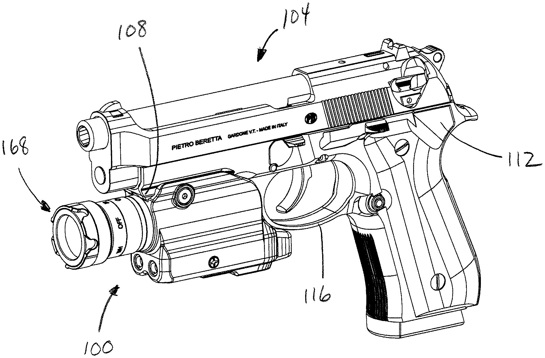
[0030] FIG. 1 is an isometric view of a flashlight assembly in accordance with an exemplary embodiment mounted to a weapon.
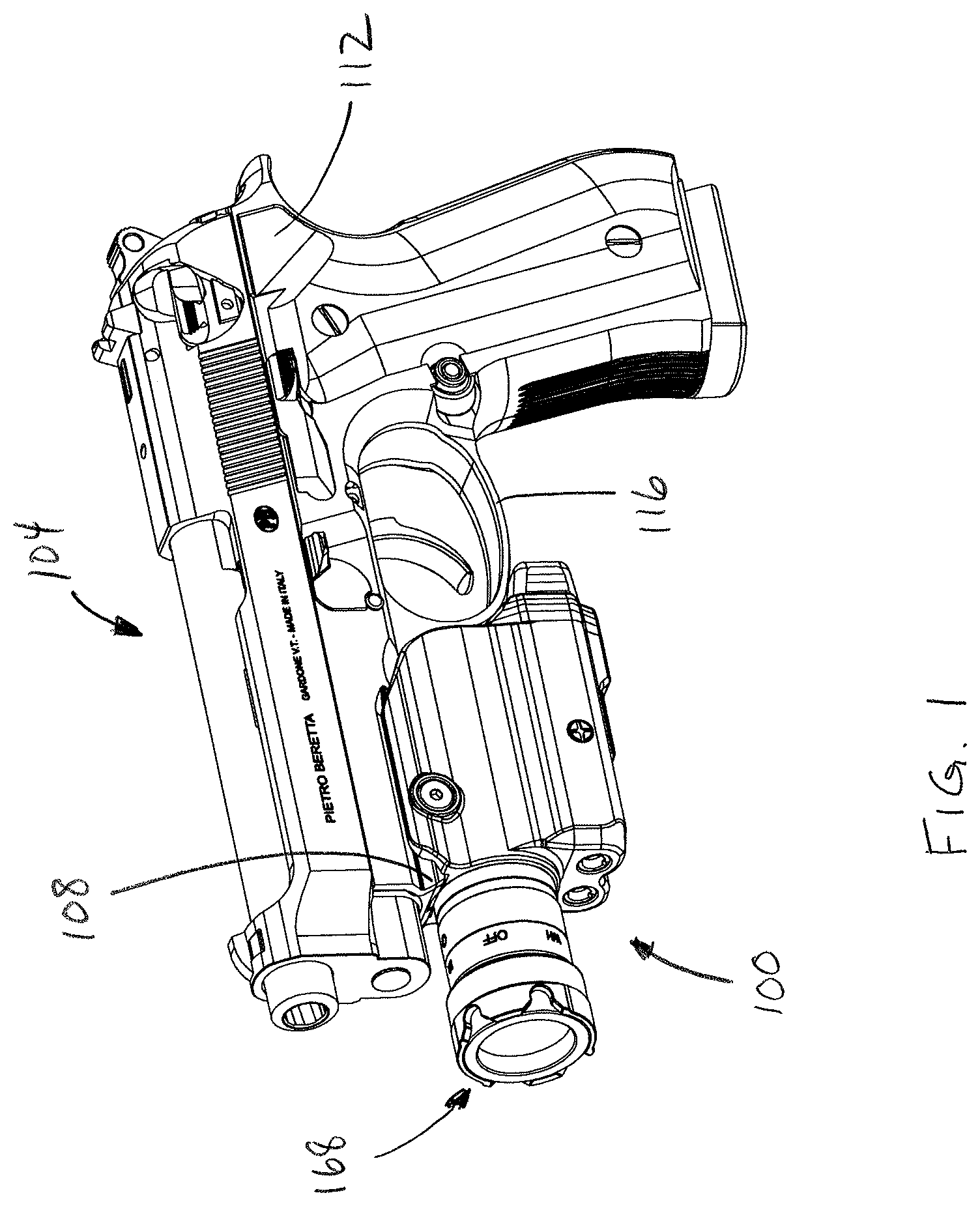
[0031] FIG. 2 is a partially exploded view of the weapon/flashlight system appearing in FIG. 1
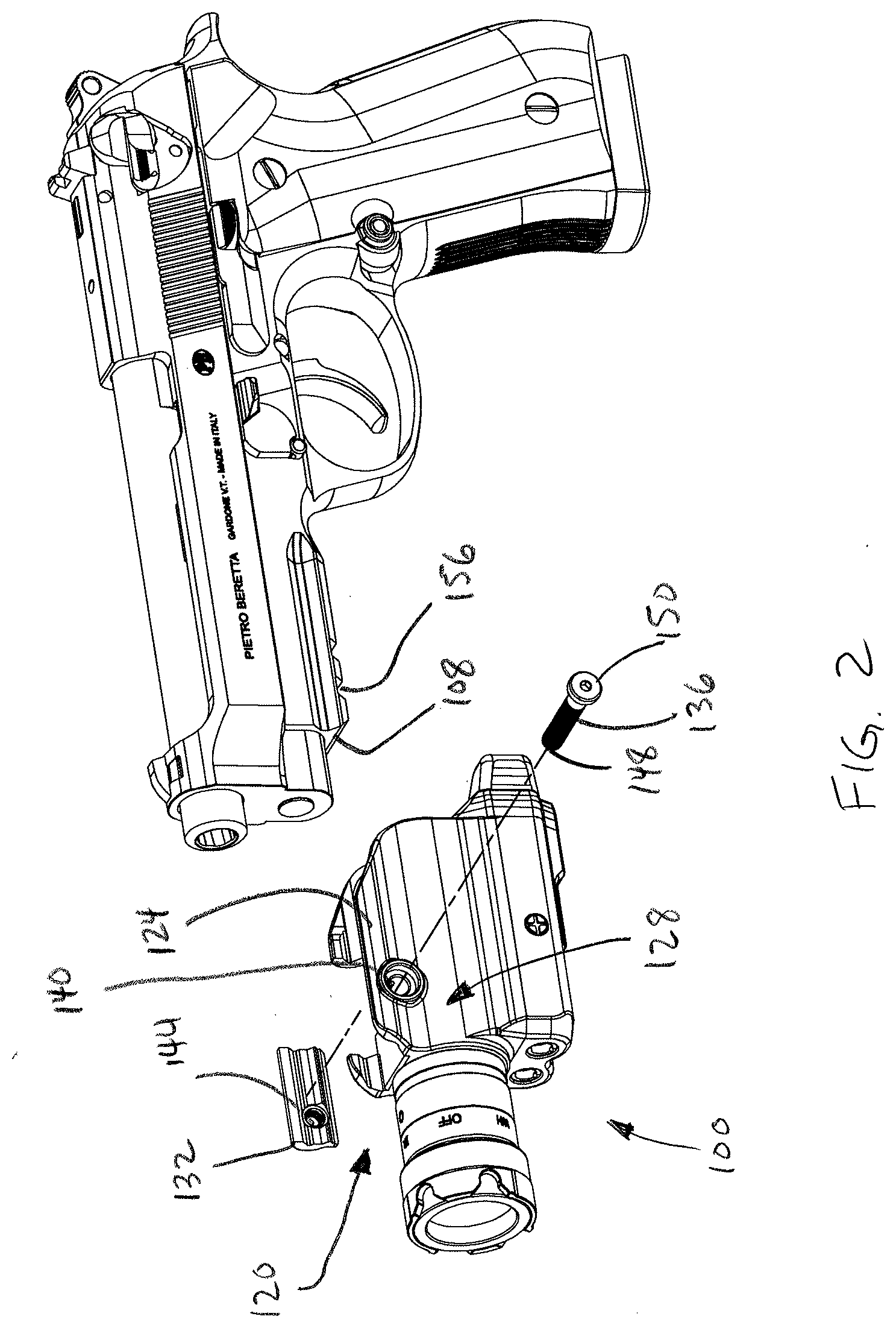
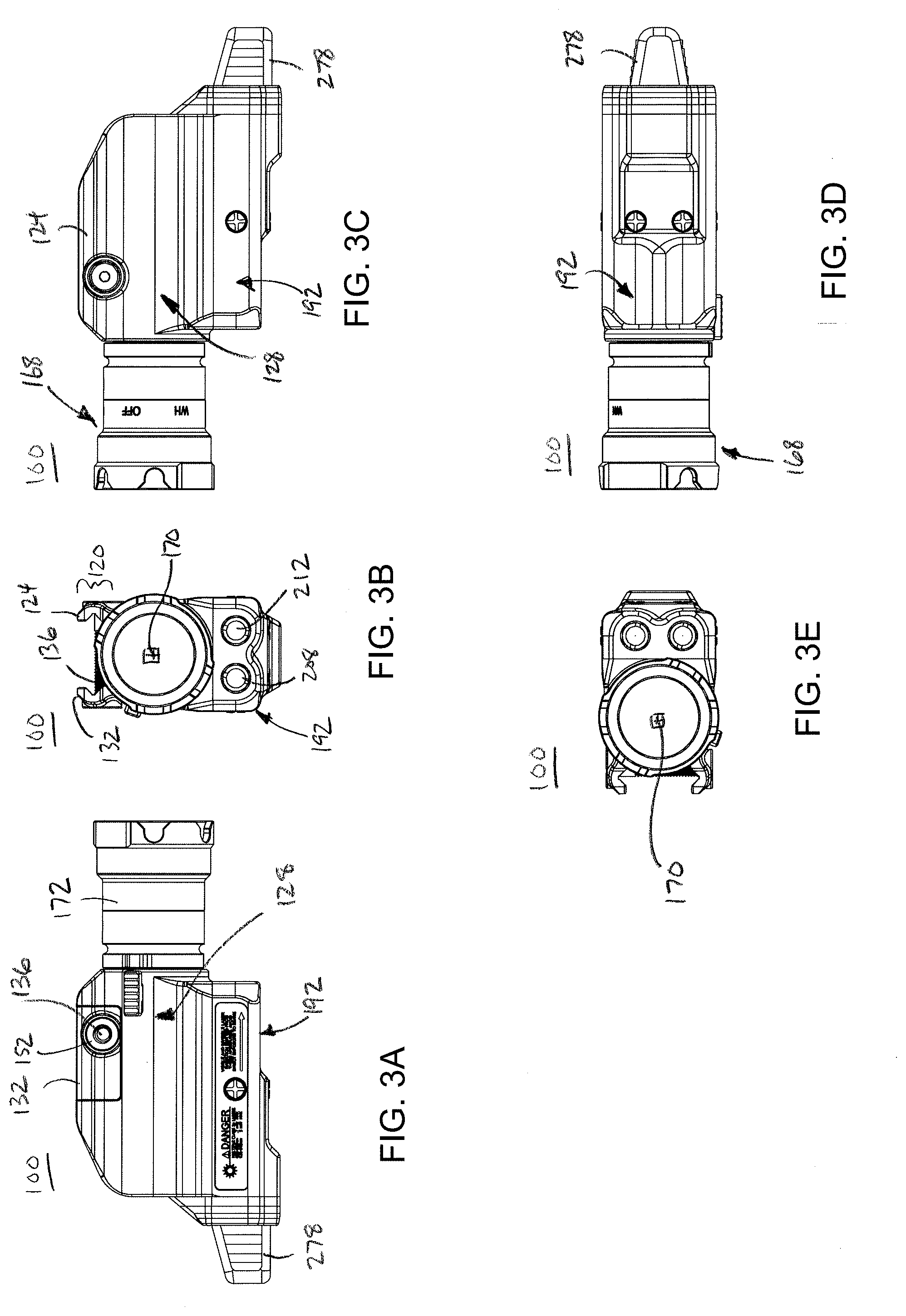
[0032] FIG. 3A is a right side elevation view of the flashlight assembly appearing in FIG. 1.
[0033] FIGS. 3B and 3E are front views of the flashlight assembly appearing in FIG. 1.
[0034] FIG. 3C is a left side elevation view of the flashlight assembly appearing in FIG. 1.
[0035] FIG. 3D is a top plan view of the flashlight assembly appearing in FIG. 1.
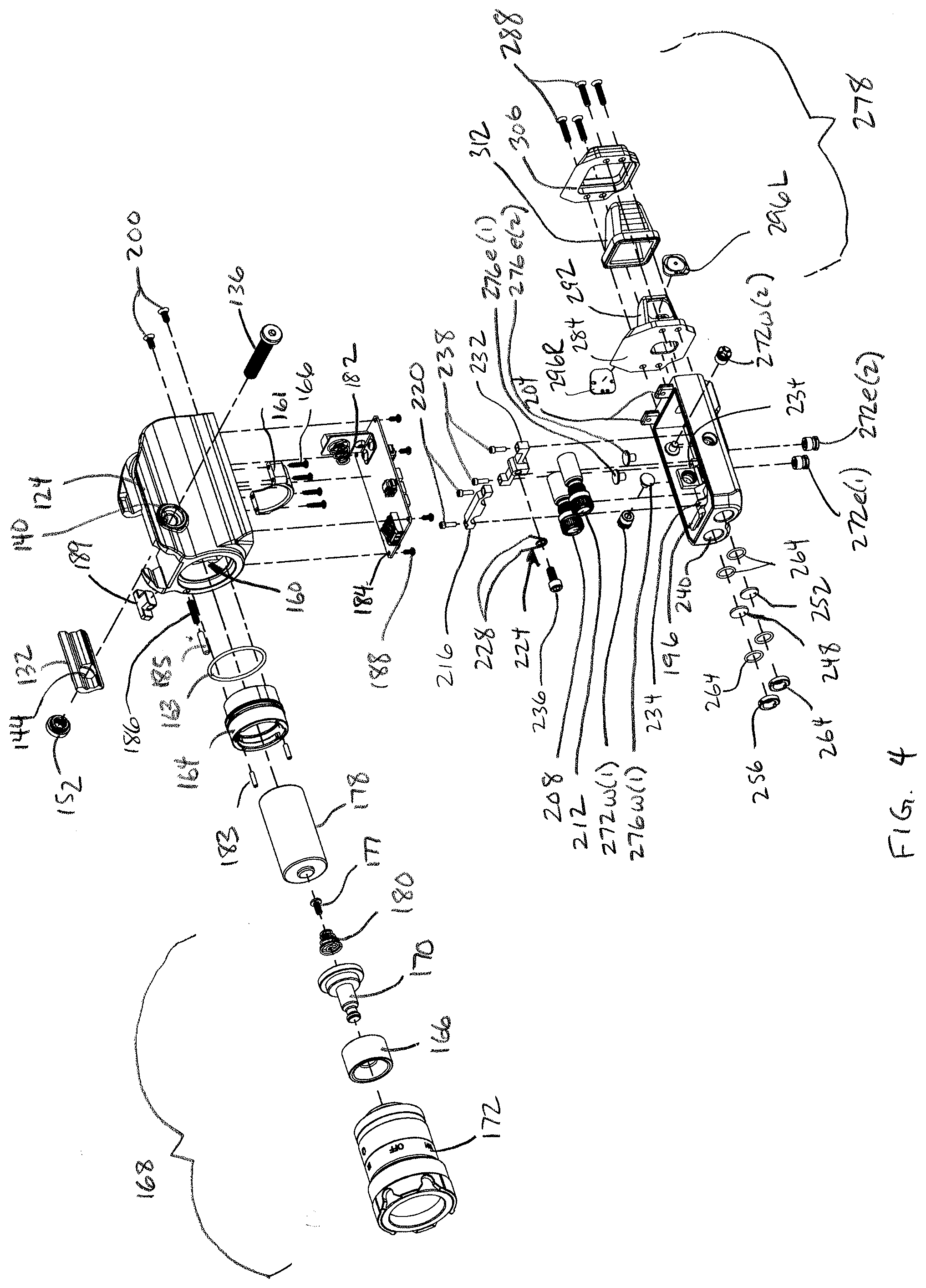
[0036] FIG. 4 is an exploded isometric view of the flashlight assembly appearing in FIG. 1, taken generally from the front and left side.
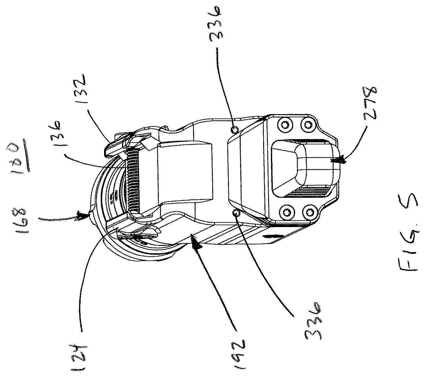
[0037] FIG. 5 is an isometric view of the flashlight assembly appearing in FIG. 1, taken generally from the rear.
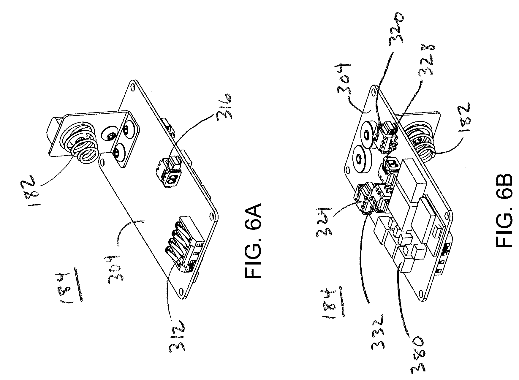
[0038] FIG. 6A is an isometric view of the circuit board (printed wire assembly) appearing in FIG. 1, taken generally from the top and front.
[0039] FIG. 6B is an isometric view of the circuit board (printed wire assembly) appearing in FIG. 1, taken generally from the bottom and front.
[0040] FIG. 7 is a partially exploded view illustrating the manner of removing the flashlight head from the main body.
[0041] FIG. 8 is an exemplary block diagram illustrating the flashlight assembly.
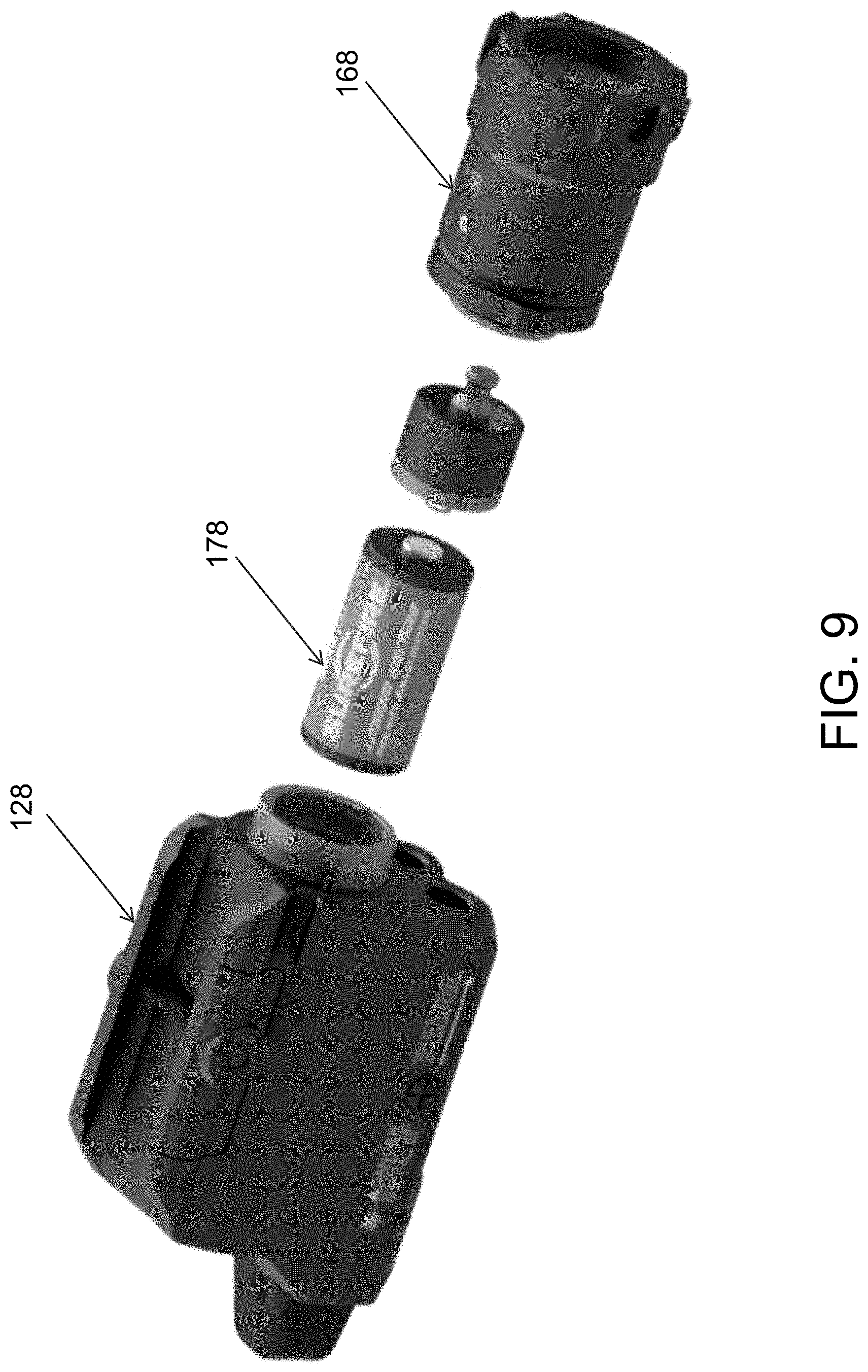
[0042] FIG. 9 is a partially exploded view illustrating the manner of replacing the battery.
DETAILED DESCRIPTION OF THE PREFERRED EMBODIMENT(S)
[0043] Referring to the drawings, a multi-function flashlight assembly, designated generally as 100, is configured for attachment to a weapon 104, such as a firearm, preferably, a handgun. In the illustrated embodiment of FIG. 1, the unit 100 is mounted to a rail interface 108 disposed on a lower receiver portion 112 of the handgun 104 at a position forward of the trigger guard 116. In certain embodiments, the rail interface 108 is a dovetail interface such as a Picatinny interface, e.g., a MIL-STD-1913 or STANAG 2324 rail interface.
[0044] Unless specifically stated otherwise, terms used herein denoting direction or orientation, such as left, right, front, rear, forward, rearward, upper, lower, horizontal, vertical, etc., are taken from the perspective of an user operating the unit 100 when the unit is mounted on a weapon, such as the handgun 104 as illustrated in FIG. 1.
[0045] As best seen in FIGS. 2 and 3B, the unit 100 includes a rail clamp interface 120 for mounting to the rail interface 108. The rail clamp interface 120 assembly includes a fixed clamping member 124 affixed to a flashlight main housing 128 on one transverse side of the flashlight housing 128. The rail clamp interface assembly 120 further includes a movable clamping member 132 disposed on the opposite transverse side of the flashlight housing 128.
[0046] A rod 136 extends through an opening 140 in the fixed clamping member 124 and an opening 144 in the movable clamping member 132. The rod 124 includes helical threads disposed at least at a distal end 148 of the rod 136. The threaded end 148 of the rod 136 rotatably engages a nut 152 (see FIG. 4) aligned with the opening 144 in the movable clamping member 132. The proximal end of the threaded rod 136 includes an enlarged diameter head 150 configured to engage a tool for rotating the rod 136 to selectively advance or retract the rod 136 relative to the nut 152, depending on the direction of rotation. In certain embodiments, the head 150 may include a tamperproof feature, such as keyed feature configured to engage a custom tool.
[0047] The rod 136 is configured to extend within a transverse recoil groove 156 in the rail interface 108. Rotation of the threaded rod 136 in one direction increases the clamping force exerted by the clamping members 124, 132, to secure the flashlight assembly 100 to the rail interface 108 and rotation of the rod 136 in the opposite direction decreases the clamping force for removal of the flashlight assembly 100 from the rail interface 108. In certain embodiments, the nut 152 may be omitted and the bore 144 within the movable clamping member 132 may be tapped with internal threads to receive the threaded end 148 of the rod 136. In certain embodiments, the rail clamp interface assembly 120 may include a cam lock having a lever and a cam surface, e.g., by providing an eccentric pivot axis, to allow for removal and attachment of the flashlight assembly without a tool.
[0048] As best seen in FIG. 4, the flashlight main housing 128 includes an opening 160 receiving a flashlight socket 164 which, in turn, receives a flashlight head 168 including a light source 170. An O-ring 163 is provided between the socket 164 and the main housing 128 to provide environmental sealing. A power contact 171 extends through an insulator 173 and electrically couples the power supply 178 to the light source 170.
[0049] In certain embodiments, the light source 170 includes a visible light source, e.g., such as a one or more white light emitting diodes (LEDs). In certain embodiments, the light source 170 includes an infrared (IR) light source, e.g., one or more IR LEDs viewable with a night vision device. In preferred embodiments, the light source 170 contains both a visible (e.g., white light) light source and an infrared light source, selectable by the user, and will be described herein primarily by way of reference thereto. In certain embodiments, IR light source is an 860 nm light source. Flashlight heads with selectable white light and IR light sources are commercially available. In certain embodiments, the flashlight head 168 is a VAMPIRE (.TM.) flashlight head available from SureFire, LLC, of Fountain Valley, Calif., having visible (e.g., white) and infrared (e.g., 860 nm) light sources, wherein LED elements of the light source 170 are selectable via a switch actuated by rotating the bezel 172.
[0050] The flashlight main housing 128 defines an interior compartment receiving one or more batteries or battery packs 178 for supplying power to the flashlight head 168 and the associated electronics, as described below. A battery saddle 161 supports the battery 178 and is secured with threaded fasteners 166. The battery 178 is inserted via the open end 160 of the main housing 128. A first terminal 180 is secured to the flashlight power contact 173 via a threaded fastener 177 and electrically couples one of the battery 178 terminals 179 to the contact 173 as well as terminal contacts 312 on a circuit board 184. A second terminal 182 on the circuit board 184 electrically couples the other battery terminal 181 to the circuit board 184. In alternative embodiments (not shown), the battery compartment may be accessed from the rear of the housing 128, e.g., via an opening covered with a cap or hinged door.
[0051] The circuit board 184, e.g., printed wire assembly (PWA), is secured to the bottom (in the orientation shown in FIG. 4) of the flashlight housing 128 via threaded fasteners 188, and is described in greater detail below. A laser housing or cover 192 is disposed over the printed wire assembly 184 and secured to the bottom of the flashlight housing 128. In the illustrated embodiment, the laser housing 192 is secured via a latch member 196 at the distal end thereof, which engages a complementary receptacle (not shown) in the flashlight housing 128. The laser housing 192 is secured at the proximal end thereof via threaded fasteners 200 engaging openings in upstanding tabs 204.
[0052] One or more (two in the illustrated embodiment) laser modules 208, 212 are disposed within the laser housing 192 and secured with a laser can clamp 216 and threaded fasteners 220. The laser modules 208, 212 are tensioned with the legs 228 of a torsion spring 224. The torsion spring 224 is disposed between the laser modules 208, 212 and secured to a spring retainer 232 via a threaded fastener 236. The spring retainer 232 is secured to mounting bosses 234 in the laser housing 192 via threaded fasteners 238. In preferred embodiments, the first laser module 208 is a visible pointing laser and the second laser module 212 is an infrared pointing laser.
[0053] The laser beams emitted by the laser modules 208, 212, pass through aligned apertures 240, 244, respectively, in the laser housing 192. Laser focusing lenses 248, 252 are retained in the respective openings 240, 244 by laser port covers 256, 260. Sealing rings or gaskets 264 may be provided to prevent moisture or external contamination from entering the interior of the laser housing 192.
[0054] A windage and elevation adjustment assembly is provided for each laser module 208, 212. Each windage and elevation adjustment assembly passes through an associated opening in the laser housing 192 and includes an external adjustment member 272e(1), 272w(1), 272e(2), and 272w(2) and an internal bearing member 276e(1), 276w(1), 276e(2), and 276w(2).
[0055] The bearing member 276e(1) bears against the rear end portion of the laser cans 208 and can be selectively advanced and retracted, depending on the direction of rotation of the external adjustment member 272e(1) to adjust the aim point of the laser in relation to the housing 192 in the vertical direction, against the urging of the tensioner 224, to thereby provide an elevation adjustment mechanism for the laser module 208.
[0056] The bearing member 276w(1) bears against the rear end portion of the laser cans 208 and can be selectively advanced and retracted, depending on the direction of rotation of the external adjustment member 272w(1) to adjust the aim point of the laser in relation to the housing 192 in the horizontal direction, against the urging of the tensioner 224, to thereby provide a windage adjustment mechanism for the laser module 208.
[0057] The bearing member 276e(2) bears against the rear end portion of the laser cans 212 and can be selectively advanced and retracted, depending on the direction of rotation of the external adjustment member 272e(2) to adjust the aim point of the laser in relation to the housing 192 in the vertical direction, against the urging of the tensioner 224, to thereby provide an elevation adjustment mechanism for the laser module 212.
[0058] The bearing member 276w(2) bears against the rear end portion of the laser cans 212 and can be selectively advanced and retracted, depending on the direction of rotation of the external adjustment member 272w(2) to adjust the aim point of the laser in relation to the housing 192 in the horizontal direction, against the urging of the tensioner 224, to thereby provide a windage adjustment mechanism for the laser module 212.
[0059] In this manner, the lasers 208, 212 can be coaligned and/or bore sighted to the weapon 104.
[0060] An activation switch assembly 278 includes a switch pod 280 having a mounting plate portion 284 secured to the proximal end of the laser housing via threaded fasteners 288. An axially extending portion 292 includes actuator switches 296L, 296R on the respective left and right transverse sides thereof. The actuator switches 296L, 296R control operation of the flashlight head 168 and the lasers 208, 212, as described in greater detail below. Providing switches 296L, 296R on both the left and right sides of the switch pod 280 allows for ambidextrous operation of the unit 100.
[0061] A bezel 300 is disposed over the switch pod 280 and secured with the threaded fasteners 288, with the axially extending portion 292 extending through an opening 308 in the bezel 300. A switch boot 312, which may be formed of a flexible material such as rubber or other natural or synthetic polymer, is disposed over the axially extending portion 292 and the actuator switches 296.
[0062] As best seen in FIGS. 6A and 6B, the printed wire assembly 184 includes a circuit board substrate 304 having a first electrical connector 312 which is electrically coupled to the power supply 178 for energizing the printed wire assembly and the components thereon. A second electrical connector 316 is electrically coupled to the first connector 312 and the flashlight head 168 for powering operation of the flashlight head 168.
[0063] A third electrical connector 320 is electrically coupled to the actuator switch 296L to receive user input from the left side actuator switch 296L. A fourth electrical connector 324 is electrically coupled to the actuator switch 296R to receive user input from the right side actuator switch 296R.
[0064] A fifth electrical connector 328 is electrically coupled to the first laser 208 to power operation of the first laser module 208. A sixth electrical connector 332 is electrically coupled to the second laser module 212 to power operation of the second laser module 212.
[0065] In certain embodiments, the actuator switches 296L, 296R provide input signals representative of button press events and button release events to an onboard microcontroller or microprocessor 332. In certain embodiments, the microprocessor includes a program of instructions stored within an associated memory to control operation of the flashlight head 168 and the laser modules 208, 212, responsive to one or more of: individual and combined button press and release events, button press and release sequences, time between button press events or time between button press and button release events, e.g., as determined by an associated clock source or oscillator 310.
[0066] A preferred configuration and method for controlling operation of the flashlight head 168 and the laser modules 208, 212 will now be provided, although it will be recognized that other configurations and methods are possible. In order to power on the unit 100, both buttons 296L, 296R are pressed and held for a predetermined time interval, e.g., three seconds. If the unit is powered on and it is desired to power off the unit 100, both buttons 296L, 296R are again pressed and held for the predetermined time interval (e.g., three seconds).
[0067] After the unit is powered on, the first button pressed becomes the "activation pad" for turning on or off the currently selected light source (namely, the flashlight head 168, the visible laser module 208, and the IR laser module 212) or combination thereof. The other button then becomes a mode select switch for cycling through the operational modes of the unit 100. A preferred set of operational modes are as follows: [0068] IR LASER ONLY [0069] IR LASER and FLASHLIGHT [0070] VIS LASER ONLY [0071] VIS LASER and FLASHLIGHT [0072] FLASHLIGHT ONLY
[0073] In certain embodiments, a visual indication of the currently selected operational mode is provided by LED indicators 336 which are visible though aligned windows in the flashlight housing 168. The LED indicators 336 may be multicolor LEDs having red, green, and blue sources which can be driven in various combinations and relative intensities to output multiple colors, wherein each mode is associated with a different color. In certain embodiments, the LED indicators 336 are self-contained RGB LEDs with an integral diffusing lens. In the illustrated embodiment, the LED indicators 336 are provided on the left and right sides of the unit 100 so at least one of the LED indicators 336 will be visible at all times to both left and right handed shooters.
[0074] In certain embodiments, wherein the flashlight head 168 has multiple light sources, such as white and infrared LED light sources, switching between light sources is accomplished via a dedicated selector switch in the flashlight head, such as a rotatable bezel switch in the case of the VAMPIRE(.TM.) flashlight head. Alternatively, a dedicated flashlight head is contemplated wherein switching between multiple light sources in the flashlight head is accomplished via the switches 296L, 296R.
[0075] In certain embodiments, the switch 296L, 296R that is designated as the activation pad is configured to toggle the currently selected light source(s) between the on and off states responsive to a single button press and release event. In certain embodiments, the switch 296L, 296R that is designated as the activation pad is configured to turn on the currently selected light source(s) during a button press and hold event and turn off the currently selected light source(s) responsive to a button release event. In certain embodiments, the switch 296L, 296R that is designated as the activation pad is configured to toggle the currently selected light source(s) between the on and off states responsive to a predetermined sequence of button press and release events, for example, pressing and releasing the activation pad twice within a relatively short period of time. Other button functions are also contemplated. For example, in certain embodiments, the buttons may be configured to control flashlight brightness or intensity and/or laser intensity.
[0076] In certain embodiments, a magnetic sensor element 380 is provided on the unit 100 to selectively activate and deactivate the unit 100 when the firearm is moved into and out of proximity of a magnet (not shown), such as a rare earth magnet, having a flux field. Preferably, the sensor element 380 is a magnetic reed switch or relay, although other devices such as a Hall effect semiconductor device. The magnet can be mounted to a holster (not shown) for the firearm 104 at a location that is in proximity to the sensor element 380 when the firearm is holstered. During operation, when the pistol is drawn from the holster, the unit 100 is activated in operator's selected mode of operation. The unit 100 is deactivated when the pistol 1204 is placed back in the holster.
[0077] Referring now to FIGS. 7 and 9, and with continued reference to FIG. 4, there is shown an exemplary attachment interface between the flashlight head 168 and the main housing 128. The socket 164 includes a sleeve 165 defining a female bayonet interface for providing a mechanical coupling with a male bayonet interface sleeve 169 on the flashlight head 168. The sleeve 169 includes radial tabs 174 each sized to pass through a respective axial slot 175 and rotatably engage an internal channel 176. Axial pins 183 within the channel 176 limit the extent of rotation, e.g., to 90 degrees. A locking pin 185 is biased toward the flashlight head by a captured spring 186 and engages a detent 187 on the flashlight head 168 to secure the flashlight head in the attached positon. The locking pin 185 is attached to a sliding tab 189. To remove the flashlight head from the main body 128, the sliding tab is manually slid in the rearward direction to disengage the locking pin 185 from the detent 187 and the flashlight head 168 is rotated until the radial tabs 174 are aligned with the axial slots 175. In alternative embodiments, other complementary coupling structures on the flashlight head 168 and main body 128 are contemplated, such as threads, a snap-fit interface, or other type of interface for providing a mechanical coupling between the flashlight head 168 and the main housing 128.
[0078] Referring now to FIG. 8, there is shown a block diagram of the flashlight assembly unit 100. A radio frequency (RF) transceiver module 340 is provided on the printed wire assembly 184 to perform wireless communication with a paired mobile device 344, 348. Although the present development will be described herein primarily by way of reference to BLUETOOTH interface, it will be recognized that the present development is equally applicable to other wireless communication protocols, including ZigBee, Wi-Fi, or other low power RF communication standard. The mobile device 344, 348 is advantageously a BLUETOOTH-enabled smartphone device, such as an iPhone device (344) or an Android device (348).
[0079] In certain embodiments, an accelerometer 352 is provided to provide a shot count function. The accelerometer 352 outputs a signal representative of movement of the handgun 104. Accelerometer signals indicative of the forces associated with firing a round are counted and logged in a shot log 356 in a memory 360. In certain embodiments, the accelerometer may also sense movement of the firearm and/or orientation of the firearm. Orientation information may be used to provide a cant indication function, e.g., using the LED indicators 336.
[0080] In certain embodiments, a temperature sensor 362 such as a thermocouple or other temperature gauge is provided is provided to monitor the temperature of the handgun. Data representative of temperature is logged in a temperature log 364 at periodic intervals to provide a temperature history of the firearm 104. The temperature log information and shot log information is also transmitted to the mobile device 344, 348, where can be stored for use with one or more applications 368, 372 on the respective devices, or transmitted to a remote location via a communications network, such as a cellular telephone network, Wi-Fi network, local area network, wide area network, or the like.
[0081] In certain embodiments, an RFID chip 376, which may be an active or passive RFID reader, is provided. In certain embodiments, the RFID reader 376 is configured to sense the proximity of an RFID tag 378 associated with the user. In certain embodiments, the RFID tag associated with the user is embedded within a wearable article 380 worn by the user, such as a tactical glove, eyewear, wristband, or other wearable article. In certain embodiments, the processor 332 is configured to allow operation of the unit 100 only when the associated tag is in proximity with the unit 100. In certain embodiments, the proximity of the RFID tag is required to operate the firearm. For example, in certain embodiments, the proximity of the associated RFID tag is required to disengage a wirelessly operated trigger lock associated with the handgun 104 and operated by a weapon system associated with the handgun 104. In certain embodiments, the trigger lock comprises a solenoid switch engaging a trigger lock via a pin or plunger operably connected to the trigger mechanisms, such that when the pin is inserted into the trigger mechanism, the trigger cannot be activated. In certain embodiments, the trigger lock mechanism may be as described in commonly owned U.S. application Ser. No. 16/275,955 filed Feb. 14, 2019, and commonly owned U.S. application Ser. No. 16/433,224 filed Jun. 6, 2019, each of which in incorporated herein by reference in its entirety.
[0082] The invention has been described with reference to the preferred embodiments. Obviously, modifications and alterations will occur to others upon reading and understanding the preceding detailed description. It is intended that the invention be construed as including all such modifications and alterations insofar as they come within the scope of the appended claims and their equivalents.
* * * * *
D00000
D00001
D00002
D00003
D00004
D00005
D00006
D00007
D00008
D00009
XML
uspto.report is an independent third-party trademark research tool that is not affiliated, endorsed, or sponsored by the United States Patent and Trademark Office (USPTO) or any other governmental organization. The information provided by uspto.report is based on publicly available data at the time of writing and is intended for informational purposes only.
While we strive to provide accurate and up-to-date information, we do not guarantee the accuracy, completeness, reliability, or suitability of the information displayed on this site. The use of this site is at your own risk. Any reliance you place on such information is therefore strictly at your own risk.
All official trademark data, including owner information, should be verified by visiting the official USPTO website at www.uspto.gov. This site is not intended to replace professional legal advice and should not be used as a substitute for consulting with a legal professional who is knowledgeable about trademark law.