Heat Pump System
ITO; Kazuhiro ; et al.
U.S. patent application number 16/640084 was filed with the patent office on 2020-06-25 for heat pump system. The applicant listed for this patent is Mitsubishi Electric Corporation. Invention is credited to Kazuhiro ITO, Shigeo TAKATA.
| Application Number | 20200200448 16/640084 |
| Document ID | / |
| Family ID | 66247212 |
| Filed Date | 2020-06-25 |


| United States Patent Application | 20200200448 |
| Kind Code | A1 |
| ITO; Kazuhiro ; et al. | June 25, 2020 |
HEAT PUMP SYSTEM
Abstract
A heat pump system includes a first air-conditioning apparatus, a ventilator, and a refrigerant circuit. The first air-conditioning apparatus includes a compressor, an outdoor-side heat exchanger, an expansion device, and an indoor-side heat exchanger, and air-conditions a first space. The ventilator includes a first auxiliary heat exchanger, and ventilates and air-conditions a second space different from the first space. In the refrigerant circuit, the compressor, the outdoor-side heat exchanger, the first auxiliary heat exchanger, the expansion device, and the indoor-side heat exchanger are sequentially connected by a refrigerant pipe to allow refrigerant to circulate. The first auxiliary heat exchanger is provided in a supply air passage in the ventilator.
| Inventors: | ITO; Kazuhiro; (Tokyo, JP) ; TAKATA; Shigeo; (Tokyo, JP) | ||||||||||
| Applicant: |
|
||||||||||
|---|---|---|---|---|---|---|---|---|---|---|---|
| Family ID: | 66247212 | ||||||||||
| Appl. No.: | 16/640084 | ||||||||||
| Filed: | October 27, 2017 | ||||||||||
| PCT Filed: | October 27, 2017 | ||||||||||
| PCT NO: | PCT/JP2017/038911 | ||||||||||
| 371 Date: | February 19, 2020 |
| Current U.S. Class: | 1/1 |
| Current CPC Class: | F24F 11/84 20180101; F25B 30/02 20130101; F24F 1/32 20130101; F25B 6/00 20130101; F25B 49/02 20130101; F25B 29/00 20130101; F25B 13/00 20130101; F25B 2600/2501 20130101; F25B 41/04 20130101; F24F 7/08 20130101; F25B 2313/0252 20130101; F25B 30/06 20130101; F24F 11/70 20180101; F25B 2700/2106 20130101; F24F 11/77 20180101; F25B 2313/0254 20130101; Y02B 30/70 20130101 |
| International Class: | F25B 30/06 20060101 F25B030/06; F24F 11/70 20060101 F24F011/70; F24F 11/84 20060101 F24F011/84; F25B 6/00 20060101 F25B006/00; F25B 29/00 20060101 F25B029/00; F25B 30/02 20060101 F25B030/02; F24F 1/32 20060101 F24F001/32 |
Claims
1. A heat pump system comprising: a first air-conditioning apparatus including a compressor, an outdoor-side heat exchanger, an expansion device, and an indoor-side heat exchanger, and configured to air-condition a first space; a ventilator including a first auxiliary heat exchanger, and configured to ventilate and air-condition a second space different from the first space; and a refrigerant circuit in which the compressor, the outdoor-side heat exchanger, the first auxiliary heat exchanger, the expansion device, and the indoor-side heat exchanger are sequentially connected by a refrigerant pipe to allow refrigerant to circulate, wherein the first auxiliary heat exchanger is provided in a supply air passage in the ventilator the ventilator includes a total heat exchanger, and the first auxiliary heat exchanger is provided in part of the supply air passage that is located leeward of the total heat exchanger.
2. (canceled)
3. The heat pump system of claim 1, wherein the refrigerant circuit includes a bypass provided to bypass the first auxiliary heat exchanger, and a flow switching device provided between the outdoor-side heat exchanger and the first auxiliary heat exchanger, and configured to switch a flow passage for the refrigerant to one of a flow passage in which the refrigerant flows into the first auxiliary heat exchanger and a flow passage in which the refrigerant flows into the bypass.
4. The heat pump system of claim 1, wherein the ventilator includes a second auxiliary heat exchanger in an exhaust air passage, the second auxiliary heat exchanger is connected in parallel with the first auxiliary heat exchanger in the refrigerant circuit, and the refrigerant circuit includes a flow switching device that is provided between the outdoor-side heat exchanger and the first auxiliary heat exchanger, and that is configured to switch a flow passage for the refrigerant to one of a flow passage in which the refrigerant flows into the first auxiliary heat exchanger and a flow passage in which the refrigerant flows into the second auxiliary heat exchanger.
5. The heat pump system of claim 1, wherein the ventilator includes a second auxiliary heat exchanger in an exhaust air passage, the second auxiliary heat exchanger is connected in parallel with the first auxiliary heat exchanger in the refrigerant circuit, and the refrigerant circuit includes a bypass provided to bypass the first auxiliary heat exchanger and the second auxiliary heat exchanger, and a flow switching device provided between the outdoor-side heat exchanger and the first auxiliary heat exchanger, and configured to switch a flow passage for the refrigerant to one of a flow passage in which the refrigerant flows into the first auxiliary heat exchanger, a flow passage in which the refrigerant flows into the second auxiliary heat exchanger, and a flow passage in which the refrigerant flows into the bypass.
6. The heat pump system of claim 4, wherein the ventilator includes a total heat exchanger, and the second auxiliary heat exchanger is provided in part of the exhaust air passage that is located leeward of the total heat exchanger.
7. The heat pump system of claim 3, further comprising a controller configured to cause the flow switching device to switch the flow passage for the refrigerant in such a manner as to reduce an internal air-conditioning load in the second space.
8. The heat pump system of claim 7, wherein the controller causes the flow switching device to switch the flow passage for the refrigerant to the flow passage in which the refrigerant flows into the first auxiliary heat exchanger, when a first condition is satisfied, in which an operation mode of the first air-conditioning apparatus is different from an operation mode of a second air-conditioning apparatus configured to air-condition the second space, the compressor of the first air-conditioning apparatus and a compressor of the second air-conditioning apparatus are both in operation, and the ventilator is in operation.
9. The heat pump system of claim 8, further comprising an outside-air temperature sensor configured to detect an outside air temperature, wherein when the first condition is satisfied, if the outside air temperature is lower than or equal to a first temperature set in advance or higher than or equal to a second temperature set in advance and higher than the first temperature, the controller causes the flow switching device to switch the flow passage for the refrigerant to the flow passage in which the refrigerant flows into the bypass.
10. The heat pump system of claim 4, further comprising: a controller configured to cause the flow switching device to switch the flow passage for the refrigerant in such a manner as to reduce an internal air-conditioning load in the second space; and an outside-air temperature sensor configured to detect an outside air temperature, wherein the controller causes the flow switching device to switch the flow passage for the refrigerant to the flow passage in which the refrigerant flows into the first auxiliary heat exchanger, when a first condition is satisfied, in which an operation mode of the first air-conditioning apparatus is different from an operation mode of a second air-conditioning apparatus configured to air-condition the second space, the compressor of the first air-conditioning apparatus and a compressor of the second air-conditioning apparatus are both in operation, and the ventilator is in operation, and wherein the controller causes the flow switching device to switch the flow passage for the refrigerant to the flow passage in which the refrigerant flows into the second auxiliary heat exchanger, when the first condition is satisfied and the outside air temperature is lower than or equal to a first temperature set in advance or higher than or equal to a second temperature set in advance and higher than the first temperature.
Description
TECHNICAL FIELD
[0001] The present disclosure relates to a heat pump system that effectively uses exhaust heat.
BACKGROUND ART
[0002] In the past, air-source heat pump type air-conditioning apparatuses have been proposed, which incorporate a total heat exchanger and a heat exchanger serving as an outdoor unit (see, for example, Patent Literature 1). The air-conditioning apparatus described in Patent Literature 1 is installed in a building to perform indoor temperature control and ventilation.
CITATION LIST
Patent Literature
[0003] Patent Literature 1: Japanese Unexamined Patent Application Publication No. 7-310964
SUMMARY OF INVENTION
Technical Problem
[0004] Such a plurality of air-conditioning apparatuses as described in Patent Literature 1 may be installed in the same building. For example, in the case where an air-conditioning apparatus is installed for an office room and another air-conditioning apparatus is installed for a computer room, during wintertime, the air-conditioning apparatus installed for the office room basically performs a heating operation, whereas the air-conditioning apparatus installed for the computer room performs a cooling operation. In this case, exhaust heat from the heat exchanger serving as the outdoor unit of the air-conditioning apparatus installed for the computer room is useful for the office room. However, in the past, such exhaust heat has been let out outdoors without being effectively used.
[0005] That is, when a plurality of air-conditioning apparatuses operate in different operation modes, exhaust heat from a heat exchanger serving as an outdoor unit of one of the air-conditioning apparatuses that is installed for a first space may be used for a second space that is different from the first space. However, even in such a case, in the past, exhaust heat from the heat exchanger serving as the outdoor unit has been let out outdoors without being effectively used.
[0006] The present disclosure is applied to solve the above problem, and relates to a heat pump system in which exhaust heat from an outdoor heat exchanger installed for a first space is effectively used in a second space different from the first space, whereby an internal air-conditioning load in the second space can be reduced and an energy efficiency can be improved to achieve energy savings.
Solution to Problem
[0007] A heat pump system according to an embodiment of the present disclosure includes: a first air-conditioning apparatus that includes a compressor, an outdoor-side heat exchanger, an expansion device, and an indoor-side heat exchanger, and that air-conditions a first space; a ventilator that includes a first auxiliary heat exchanger, and ventilates and air-conditions a second space different from the first space; and a refrigerant circuit in which the compressor, the outdoor-side heat exchanger, the first auxiliary heat exchanger, the expansion device, and the indoor-side heat exchanger are sequentially connected by a refrigerant pipe to allow refrigerant to circulate. The first auxiliary heat exchanger is provided in a supply air passage in the ventilator.
Advantageous Effects of Invention
[0008] The heat pump system according to the embodiment of the present disclosure includes the refrigerant circuit in which the compressor, the outdoor-side heat exchanger, the first auxiliary heat exchanger, the expansion device, and the indoor-side heat exchanger are sequentially connected by the refrigerant pipe to allow refrigerant to circulate, and the first auxiliary heat exchanger is provided in the supply air passage of the ventilator. Because of this configuration, exhaust heat from the outdoor-side heat exchanger installed for the first space can be used to regulate the temperature of air supplied from the ventilator installed for the second space different from the first space. It is therefore possible to reduce the internal air-conditioning load in the second space and improve an energy efficiency to achieve energy savings.
BRIEF DESCRIPTION OF DRAWINGS
[0009] FIG. 1 is a schematic diagram illustrating a configuration of a heat pump system according to Embodiment 1 of the present disclosure.
[0010] FIG. 2 is a first detailed configuration diagram of the heat pump system according to Embodiment 1 of the present disclosure.
[0011] FIG. 3 is a second detailed configuration diagram of the heat pump system according to Embodiment 1 of the present disclosure.
[0012] FIG. 4 indicates an example of conditions for controlling a second flow switching device of the heat pump system according to Embodiment 1 of the present disclosure.
[0013] FIG. 5 illustrates a control flow diagram of the heat pump system according to Embodiment 1 of the present disclosure.
[0014] FIG. 6 is a detailed configuration diagram of a heat pump system according to Embodiment 2 of the present disclosure.
[0015] FIG. 7 indicates an example of conditions for controlling a second flow switching device of the heat pump system according to Embodiment 2 of the present disclosure.
[0016] FIG. 8 is a control flow diagram of the heat pump system according to Embodiment 2 of the present disclosure.
[0017] FIG. 9 is a detailed configuration diagram of a heat pump system according to Embodiment 3 of the present disclosure.
[0018] FIG. 10 indicates an example of conditions for controlling a second flow switching device of the heat pump system according to Embodiment 3 of the present disclosure.
[0019] FIG. 11 is a control flow diagram of the heat pump system according to Embodiment 3 of the present disclosure.
[0020] FIG. 12 is a diagram illustrating an example of the second flow switching device of the heat pump system according to Embodiment 3 of the present disclosure.
[0021] FIG. 13 is a diagram illustrating another example of the second flow switching device of the heat pump system according to Embodiment 3 of the present disclosure.
[0022] FIG. 14 illustrates examples of an operation of the second flow switching device of the heat pump system according to Embodiment 3 of the present disclosure operates.
[0023] FIG. 15 is a first detailed configuration diagram of a heat pump system according to Embodiment 4 of the present disclosure.
[0024] FIG. 16 is a second detailed configuration diagram of the heat pump system according to Embodiment 4 of the present disclosure.
DESCRIPTION OF EMBODIMENTS
[0025] The embodiments of the present disclosure will be described with reference to the drawings. It should be noted that the following descriptions concerning Embodiments 1 to 4 are not limitative. Relationships between dimensions of components illustrated in the drawings may differ from actual ones.
Embodiment 1
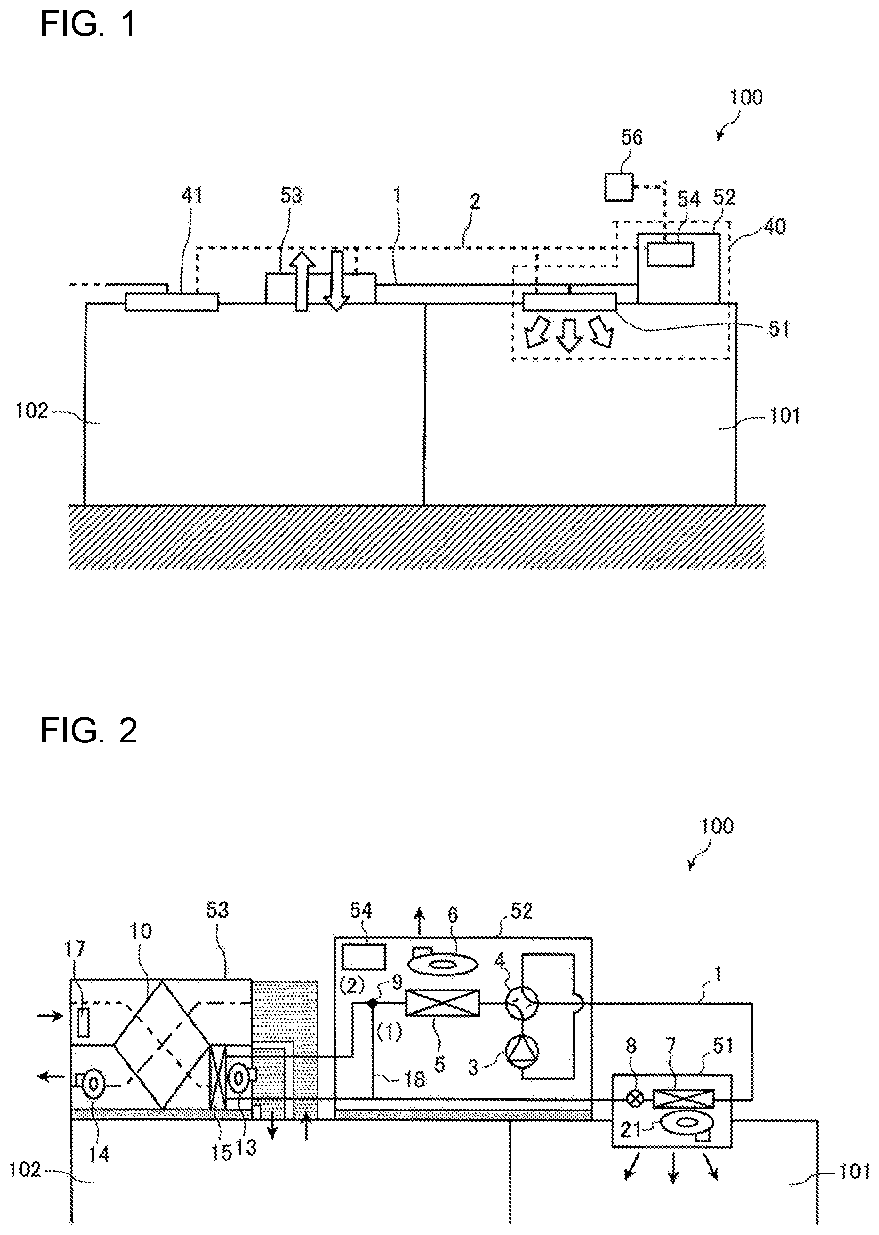
[0026] FIG. 1 is a schematic diagram illustrating a configuration of a heat pump system 100 according to Embodiment 1 of the present disclosure.
[0027] As illustrated in FIG. 1, the heat pump system 100 according to Embodiment 1 includes an air-conditioning apparatus 40, a ventilator 53, and a controller 54.
[0028] The air-conditioning apparatus 40 is installed for a first space 101, and air-conditions the first space 101. The air-conditioning apparatus 40 includes an indoor unit 51 and an outdoor unit 52. The ventilator 53 is installed for a second space 102, and ventilates and air-conditions the second space 102. The indoor unit 51, the outdoor unit 52, and the ventilator 53 are connected by a refrigerant pipe 1. The first space 101 and the second space 102 are different spaces.
[0029] The controller 54 is housed in the indoor unit 52. The controller 54 is connected to the indoor unit 51, the outdoor unit 52, and the ventilator 53 by communication transmission lines 2. The controller 54 monitors the operating state of each of devices (the indoor unit 51, the outdoor unit 52, and the ventilator 53), and gives an output instruction to each of actuators of he devices. A remote control unit 56 is connected to the controller 54 either wirelessly or by a signal line. It is therefore possible to change, using the remote control unit 56, an on/off state such as whether each device is in operation or stopped state, i.e., in on state or off state, an operation mode, a set temperature, the amount of air, etc., of each device.
[0030] It should be noted that although with respect to Embodiment 1, although it is described that the controller 54 is provided in the outdoor unit 52, it is not limited where the controller 54 is provided. For example, the controller 54 may be provided in the indoor unit 51.
[0031] An air-conditioning apparatus 41 as illustrated in FIG. 1 will be described later on.
[0032] FIG. 2 is a first detailed configuration diagram of the heat pump system 100 according to Embodiment 1 of the present disclosure. FIG. 3 is a second detailed configuration diagram of the heat pump system 100 according to Embodiment 1 of the present disclosure.
[0033] As illustrated in FIGS. 2 and 3, the indoor unit 51 includes an indoor-side heat exchanger 7, an expansion device 8, and an indoor fan 21. The outdoor unit 52 includes a compressor 3, a first flow switching device 4, an outdoor-side heat exchanger 5, an outdoor fan 6, and a second flow switching device 9. The ventilator 53 includes a total heat exchanger 10, a supply air fan 13, an exhaust air fan 14, a first auxiliary heat exchanger 15, and an outside-air temperature sensor 17.
[0034] The heat pump system 100 includes a refrigerant circuit in which the compressor 3, the first flow switching device 4, the outdoor-side heat exchanger 5, the second flow switching device 9, the first auxiliary heat exchanger 15, the expansion device 8, and the indoor-side heat exchanger 7 are sequentially connected by refrigerant pipes 1 to allow refrigerant to circulate. The refrigerant circuit includes a bypass 18 that bypasses the first auxiliary heat exchanger 15.
[0035] The first flow switching device 4 switches the flow direction of refrigerant between an .alpha.-direction (indicated by a solid line in FIG. 3) in which the refrigerant flows from the discharge side of the compressor 3 toward the outdoor-side heat exchanger 5 and a .beta.-direction (indicated by a broken line in FIG. 3) in which the refrigerant flows from the discharge side of the compressor 3 toward the indoor-side heat exchanger 7. The first flow switching device 4 is, for example, a four-way valve.
[0036] Also, the second flow switching device 9 switches the flow direction of refrigerant between a first direction (corresponding to passage (1) in FIG. 3) in which the refrigerant bypasses the first auxiliary heat exchanger 15 and passes through the bypass 18 and a second direction (corresponding to passage (2) in FIG. 3) in which the refrigerant passes through the first auxiliary heat exchanger 15. The second flow switching device 9 is, for example, a three-way valve.
[0037] To explain the operation of the heat pump system 100, it will be described how the air-conditioning apparatus 40 that air-conditions the first space 101 operates during the cooling operation and the heating operation, and also how the ventilator 53 that ventilates and air-conditions the second space 102 operates.
[0038] [Cooling Operation]
[0039] In the cooling operation of the air-conditioning apparatus 40, the first flow switching device 4 switches the flow direction of the refrigerant to the .alpha.-direction. When the second flow switching device 9 switches the flow direction of the refrigerant to the first direction, high-temperature, high-pressure refrigerant discharged by the compressor 3 passes through the outdoor-side heat exchanger 5 and condenses. By contrast, when the second flow switching device 9 switches the flow direction of the refrigerant to the second direction, the high-temperature, high-pressure refrigerant discharged by the compressor 3 sequentially passes through the outdoor-side heat exchanger 5 and the first auxiliary heat exchanger 15 and condenses.
[0040] The refrigerant that has condensed is reduced in pressure by the expansion device 8 to change into low-temperature, low-pressure refrigerant. The low-temperature, low-pressure refrigerant flows into the indoor-side heat exchanger 7, exchanges heat with indoor air in the first space 101, and evaporates. The refrigerant that has evaporated is sucked into the compressor 3 and compressed thereby into high-temperature, high-pressure refrigerant. The high-temperature, high-pressure refrigerant is re-discharged from the compressor 3. Then, the refrigerant is repeatedly subjected to the above processes and flows in the above manner. By contrast, air subjected to heat exchange at the indoor-side heat exchanger 7 is blown out into the first space 101.
[0041] [Heating Operation]
[0042] In the heating operation of the air-conditioning apparatus 40, the first flow switching device 4 switches the flow direction of refrigerant to the .beta.-direction. The high-temperature, high-pressure refrigerant discharged by the compressor 3 flows into the indoor-side heat exchanger 7, exchanges heat with indoor air in the first space 101, and condenses. The refrigerant that has condensed is reduced in pressure by the expansion device 8. When the second flow switching device 9 switches the flow direction of the refrigerant to the first direction, the refrigerant that has been reduced in pressure passes through the outdoor-side heat exchanger 5 and evaporates. By contrast, when the second flow switching device 9 switches the flow direction of the refrigerant to the second direction, the refrigerant that has been reduced in pressure sequentially passes through the first auxiliary heat exchanger 15 and the outdoor-side heat exchanger 5 and evaporates.
[0043] The refrigerant that has evaporated is sucked into the compressor 3, and compressed into high-temperature, high-pressure refrigerant. The high-temperature, high-pressure refrigerant is re-discharged from the compressor 3. Then, the refrigerant is repeatedly subjected to the above processes and flows in the above manner. By contrast, air subjected to heat exchange at the indoor-side heat exchanger 7 is blown out into the first space 101.
[0044] The ventilator 53 causes air taken in from the outdoor space to exchange heat with air let out from the second space 102, and then supplies the air into the second space 102. The supply air fan 13 produces, in a supply air passage 11, an air flow for taking air from the outdoor space into the second space 102. The exhaust air fan 14 produces, in an exhaust air passage 12, an air flow for letting out air from the second space 102 to the outdoor space. The total heat exchanger 10 causes heat exchange to be performed between air that flows in the supply air passage 11 and air that flows in the exhaust air passage 12.
[0045] The first auxiliary heat exchanger 15 is installed in part of the supply air passage 11 that is located leeward of the total heat exchanger 10, i.e., that is located between the total heat exchanger 10 and the supply air fan 13. The first auxiliary heat exchanger 15 causes air that has passed through the total heat exchanger 10 to exchange heat with refrigerant. The ventilator 53 is also configured to cause air taken from the outdoor space into the ventilator 53 to pass through the total heat exchanger 10 and then pass through the first auxiliary heat exchanger 15. Because of this configuration, heat is not taken away by exhaust air, and can thus be efficiently used. After passing through the first auxiliary heat exchanger 15, the air is supplied into the second space 102.
[0046] Also, the outside-air temperature sensor 17 is provided in part of the supply air passage 11 that is located windward of the total heat exchanger 10. The outside-air temperature sensor 17 is, for example, a thermistor, and detects the temperature of outside air, i.e., outside air temperature. Information on the outside air temperature detected by the outside-air temperature sensor 17 (which will be hereinafter referred to as outside-air temperature information) is sent to the controller 54.
[0047] Although regarding Embodiment 1, it is described above that the outside-air temperature sensor 17 is included in the ventilator 53, this is not limitative. Also, it is not limited where the outside-air temperature sensor 17 is provided. For example, the outside-air temperature sensor 17 may be installed outside the ventilator 53.
[0048] Furthermore, during the cooling operation of the air-conditioning apparatus 40, when the second flow switching device 9 switches a flow passage for the refrigerant to a flow passage in which the refrigerant passes through the first auxiliary heat exchanger 15, air warmed up at the first auxiliary heat exchanger 15 is supplied into the second space 102.
[0049] It should be noted that in the case where during the cooling operation of the air-conditioning apparatus 40, the refrigerant is made to flow through the first auxiliary heat exchanger 15, it is appropriate that the rotation speed of the outdoor fan 6, the rotation speed of the supply air fan 13, and the rotation speed of the exhaust air fan 14 are regulated.
[0050] When the rotation speed of the outdoor fan 6, the rotation speed of the supply air fan 13, and the rotation speed of the exhaust air fan 14 are regulated, the amount of heat that is transferred at the outdoor-side heat exchanger 5 and that at the first auxiliary heat exchanger 15 can be regulated. Because of this regulation, the amount of condensation at the outdoor-side heat exchanger 5 and that at the first auxiliary heat exchanger 15 are controlled, whereby the operation of the refrigeration cycle circuit is stabilized, and the amount of heat that is transferred at the first auxiliary heat exchanger 15 is regulated. Thus, the amount of heat that is supplied to the second space 102 can be regulated.
[0051] For example, in the case where during the cooling operation of the air-conditioning apparatus 40, the refrigerant is made to flow through the first auxiliary heat exchanger 15, the rotation speed of the outdoor fan 6 is set lower than in the case where the refrigerant is not made to flow through the first auxiliary heat exchanger 15.
[0052] During the heating operation of the air-conditioning apparatus 40, when the second flow switching device 9 switches the flow passage for the refrigerant to the flow passage in which the refrigerant passes through the first auxiliary heat exchanger 15, air cooled at the first auxiliary heat exchanger 15 is supplied into the second space 102.
[0053] In the case where during heating operation of the air-conditioning apparatus 40, the refrigerant is made to flow through the first auxiliary heat exchanger 15, it is appropriate that the rotation speed of the outdoor fan 6, the rotation speed of the supply air fan 13, and the rotation speed of the exhaust air fan 14 are regulated.
[0054] When the rotation speed of the outdoor fan 6, the rotation speed of the supply air fan 13, and the rotation speed of the exhaust air fan 14 are regulated, the amount of heat that is transferred at the outdoor-side heat exchanger 5 and that at the first auxiliary heat exchanger 15 can be regulated. Because of this regulation, the amount of evaporation at the outdoor-side heat exchanger 5 and that at the first auxiliary heat exchanger 15 are controlled, whereby the operation of the refrigeration cycle circuit is stabilized, and the amount of heat that is transferred at the first auxiliary heat exchanger 15 is regulated. Thus, the amount of heat that is supplied to the second space 102 can be regulated.
[0055] For example, in the case where during the heating operation of the air-conditioning apparatus 40, the refrigerant is passed through the first auxiliary heat exchanger 15, the rotation speed of the outdoor fan 6 is set lower than in the case where the refrigerant is not passed through the first auxiliary heat exchanger 15.
[0056] As described above, in the heat pump system 100 according to Embodiment 1, in the case where the first space 1 is air-conditioned, heat that is released to the outdoor space by the outdoor-side heat exchanger 5 can be used to air-condition the second space 102. That is, since the heat pump system 100 according to Embodiment 1 can perform air-conditioning using exhaust heat, the energy efficiency of the entire heat pump system 100 can be improved to achieve energy savings. Also, in the heat pump system 100 according to Embodiment 1, the amount of heat that is transferred at the outdoor-side heat exchanger 5 can be reduced, heat-island phenomenon and cold-island phenomenon can thus be reduced.
[0057] FIG. 4 indicates an example of the conditions for controlling the second flow switching device 9 of the heat pump system 100 according to Embodiment 1 of the present disclosure. In FIG. 4, "-" means that related determinations are made regardless of the conditions indicated by "-".
[0058] In an operation example indicated in FIG. 4, the air-conditioning apparatus 41 (see FIG. 1) is installed in the second space 102. The air-conditioning apparatus 41 is different from the air-conditioning apparatus 40 installed in the first space 101. For example, the air-conditioning apparatus 41 air-conditions the second space 102 using the refrigeration cycle circuit. The air-conditioning apparatus 41 is connected to the controller 54 by a communication transmission line 2.
[0059] As indicated in FIG. 4, the heat pump system 100 determines the flow direction of the refrigerant that is to be set by the second flow switching device 9, based on the operating states (operation mode and thermo-state) of the air-conditioning apparatus 40 installed in the first space 101, the operating states (operation mode and thermo-state) of the air-conditioning apparatus 41 installed in the second space 102, and the operating state of the ventilator 53 installed in the second space 102 (whether the ventilator 53 is in operation or stopped state).
[0060] FIG. 5 is a control flow diagram of the heat pump system 100 according to Embodiment 1 of the present disclosure.
[0061] A control by the heat pump system 100 of Embodiment 1 will be described with reference to FIG. 5.
[0062] The controller 54 acquires the operation information on the air-conditioning apparatus 40 installed in the first space 101 (step S101) and also acquires the operation information on the air-conditioning apparatus 41 and ventilator 53 installed in the second space 102 (step S102). The controller 54 also acquires the outside-air temperature information (step S103).
[0063] The operation information on the air-conditioning apparatus 40 includes the operation mode and the thermo-state of the air-conditioning apparatus 40. The operation information on the air-conditioning apparatus 41 includes the operation mode and the thermo-state of the air-conditioning apparatus 41. The operation information on the ventilator 53 includes on/off state information indicating whether the ventilator 53 is in operation or stopped state.
[0064] After step S103, the controller 54 determines, on the basis of each operation information, whether the operation mode of the air-conditioning apparatus 40 is the same as the operation mode of the air-conditioning apparatus 41 or not (step S104).
[0065] When determining in step S104 that the operation mode of the air-conditioning apparatus 40 is the same as the operation mode of the air-conditioning apparatus 41 (YES in step S104), the controller 54 causes the second flow switching device 9 to switch the flow direction of the refrigerant to the first direction (step S105). By contrast, when the controller 54 determines that the operation mode of the air-conditioning apparatus 40 is different from the operation mode of the air-conditioning apparatus 41 (NO in step S104), the process proceeds to step S106.
[0066] In step S106, the controller 54 determines, on the basis of each operation information, whether or not the air-conditioning apparatus 40 is in thermo-on state and the air-conditioning apparatus 41 is in thermo-on state. It should be noted that "air-conditioning apparatus 40 is in thermo-on state" means that the compressor 3 of the air-conditioning apparatus 40 is in operation. Similarly, "air-conditioning apparatus 41 is thermo-on state" means that a compressor (not illustrated) of the air-conditioning apparatus 41 is in operation.
[0067] When determining in step S106 that at least one of the air-conditioning apparatus 40 and the air-conditioning apparatus 41 is not in thermo-on state (NO in step S106), the controller 54 causes the second flow switching device 9 to switch the flow direction of the refrigerant to the first direction (step S110). By contrast, when the controller 54 determines that the air-conditioning apparatus 40 is in thermo-on state and the air-conditioning apparatus 41 is also in thermo-on state (YES in step S106), the process proceeds to step S107.
[0068] In step S107, the controller 54 determines, on the basis of each operation information, whether the ventilator 53 is in operation or not. When determining that the ventilator 53 is not in operation (NO in step S107), the controller 54 causes the second flow switching device 9 to switch the flow direction of the refrigerant to the first direction (step S110). By contrast, when the controller 54 determines that the ventilator 53 is in operation (YES in step S107), the process proceeds to step S108.
[0069] In step S108, the controller 54 determines, on the basis of outside-air temperature information, whether the outside air temperature is higher than a first temperature set in advance and is lower than a second temperature set in advance. It should be noted that the first temperature is a low temperature threshold at which the operation of the refrigeration cycle circuit becomes unstable, and the second temperature is a high temperature threshold at which the operation of the refrigeration cycle circuit becomes unstable.
[0070] When determining in step S108 that the outside air temperature is higher than the first temperature and lower than the second temperature (YES in step S108), the controller 54 causes the second flow switching device 9 to switch the flow direction of the refrigerant to the second direction (step S109). By contrast, when determining that the outside air temperature is lower than or equal to the first temperature, or higher than or equal to the second temperature (NO in step S108), the controller 54 causes the second flow switching device 9 to switch the flow direction of the refrigerant to the first direction (step S110).
[0071] As described above, when the operation modes of the air-conditioning apparatuses 40 and 41 are different from each other, the air-conditioning apparatuses 40 and 41 are both in thermo-on state, and the ventilator 53 is in operation, the controller 54 causes the second flow switching device 9 to switch the flow direction of the refrigerant to the second direction in accordance with the outside air temperature. In such a manner, because of the control of the second flow switching device 9, exhaust heat from the air-conditioning apparatus 40 installed in the first space 101 can be used in the second space 102. It is therefore possible to reduce the internal air-conditioning load in the second space 102 and improve the energy efficiency of the heat pump system 100 to achieve energy savings.
[0072] When the outside air temperature is low or high to cause the operation of the refrigeration cycle circuit to be unstable, priority is given to stabilization of the operation of the refrigeration cycle circuit. Therefore, the flow direction set by the second flow switching device 9 is not switched to the second direction. When the ventilator 53 is in operation, priority is given to control of the ventilation. It is therefore hard to control the amount of air in the supply air passage 11 or the exhaust air passage 12 of the ventilator 53 in such a manner as to stabilize the operation of the refrigeration cycle circuit. In this case, the flow direction set by the second flow switching device 9 is switched to the first direction to give priority to stabilization of the operation of the refrigeration cycle circuit.
[0073] The heat pump system 100 according to Embodiment 1 can be simply configured to incorporate an auxiliary heat exchanger unit 500 (see FIG. 3) in which the second flow switching device 9 and the first auxiliary heat exchanger 15 are connected by the refrigerant pipe 1. That is, the heat pump system 100 can be formed simply by connecting the auxiliary heat exchanger unit 500 to an existing refrigeration cycle apparatus.
[0074] The heat pump system 100 of Embodiment 1 is not limited to the example described above. To be more specific, it is not indispensable that the first auxiliary heat exchanger 15 is provided in the supply air passage 11. That is, it suffices that the first auxiliary heat exchanger 15 is provided in the second space 102 different from the first space 101 to supply heat to the second space 102.
[0075] As described above, the heat pump system 100 according to Embodiment 1 includes: the air-conditioning apparatus 40 that includes the compressor 3, the outdoor-side heat exchanger 5, the expansion device 8, and the indoor-side heat exchanger 7, and that air-conditions the first space 101; the ventilator 53 that includes the first auxiliary heat exchanger 15, and ventilates and air-conditions the second space 102 different from the first space 101; and the refrigerant circuit in which the compressor 3, the outdoor-side heat exchanger 5, the first auxiliary heat exchanger 15, the expansion device 8, and the indoor-side heat exchanger 7 are sequentially connected by the refrigerant pipes 1 to allow refrigerant to circulate. The first auxiliary heat exchanger 15 is provided in the supply air passage 11 of the ventilator 53.
[0076] The heat pump system 100 according to Embodiment 1 includes the refrigerant circuit in which the compressor 3, the outdoor-side heat exchanger 5, the first auxiliary heat exchanger 15, the expansion device 8, and the indoor-side heat exchanger 7 are sequentially connected by the refrigerant pipes 1 to allow refrigerant to circulate. The first auxiliary heat exchanger 15 is provided in the supply air passage 11 of the ventilator 53. Because of this configuration, exhaust heat from the outdoor-side heat exchanger 5 installed for the first space 101 can be used to regulate the temperature of air that is supplied from the ventilator 53 installed for the second space 102 different from the first space 101. It is therefore possible to reduce the internal air-conditioning load in the second space 102 and improve the energy efficiency to achieve energy savings.
[0077] In the heat pump system 100 according to Embodiment 1, the first auxiliary heat exchanger 15 is provided in the part of the supply air passage 11 that is located leeward of the total heat exchanger 10. The heat pump system 100 according to Embodiment 1 is configured to cause air taken from the outdoor space into the ventilator 53 to pass through the total heat exchanger 10 and then pass through the first auxiliary heat exchanger 15. It is therefore possible to prevent heat from being removed by exhaust air and thus efficiently use heat.
[0078] Furthermore, in the heat pump system 100 according to Embodiment 1, the controller 54 causes the second flow switching device 9 to switch the flow passage for the refrigerant to the flow passage in which the refrigerant flows into the first auxiliary heat exchanger 15, when the following first condition is satisfied: the operation mode of the air-conditioning apparatus 40 that air-conditions the first space 101 is different from that of the air-conditioning apparatus 41 that air-conditions the second space 102; the compressor 3 of the air-conditioning apparatus 40 and the compressor (not illustrated) of the air-conditioning apparatus 41 are both in operation; and the ventilator 53 is in operation.
[0079] In the heat pump system 100 according to Embodiment 1, the second flow switching device 9 is controlled in the above manner, whereby exhaust heat from the air-conditioning apparatus 40 installed in the first space 101 can be used in the second space 102. It is therefore possible to reduce the internal air-conditioning load in the second space 102 and improve the energy efficiency of the heat pump system 100 to achieve energy savings.
[0080] In the heat pump system 100 according to Embodiment 1, when the first condition is satisfied and the outside air temperature is lower than or equal to the predetermined first temperature or higher than or equal to the second temperature set in advance and higher than the first temperature, the controller 54 causes the second flow switching device 9 to switch the flow passage for the refrigerant to a flow passage in which the refrigerant flows into the bypass 18.
[0081] If the operation of the refrigeration cycle circuit is unstable, the heat pump system 100 according to Embodiment 1 can give priority to stabilization of the operation of the refrigeration cycle circuit.
Embodiment 2
[0082] Embodiment 2 of the present disclosure will be described. It should be noted that with respect to Embodiment 2, part of the above description regarding Embodiment 1 that can also be applied to Embodiment 2 will not be repeated, and components that are the same as or equivalent to those in Embodiment 1 will be denoted by the same reference signs.
[0083] FIG. 6 is a detailed configuration diagram of the heat pump system 100 according to Embodiment 2 of the present disclosure. As illustrated in FIG. 6, in Embodiment 2, the first auxiliary heat exchanger 15 is provided in the part of the supply air passage 11 that is located between the total heat exchanger 10 and the supply air fan 13, and a second auxiliary heat exchanger 16 is provided in part of the exhaust air passage 12 that is located between the total heat exchanger 10 and the exhaust air fan 14.
[0084] The heat pump system 100 includes a refrigerant circuit in which the compressor 3, the first flow switching device 4, the outdoor-side heat exchanger 5, the second flow switching device 9, the first auxiliary heat exchanger 15, the expansion device 8, and the indoor-side heat exchanger 7 are sequentially connected by the refrigerant pipes 1 to allow refrigerant to circulate. Furthermore, in the refrigerant circuit, the second auxiliary heat exchanger 16 is connected in parallel with the first auxiliary heat exchanger 15.
[0085] The second flow switching device 9 switches the flow direction of the refrigerant to one of the second direction (corresponding to passage (2) in FIG. 6) in which the refrigerant flows through the first auxiliary heat exchanger 15 and a third direction (corresponding to passage (3) in FIG. 6) in which the refrigerant flows through the second auxiliary heat exchanger 16.
[0086] The second auxiliary heat exchanger 16 causes air that has passed through the total heat exchanger 10 to exchange heat with the refrigerant. The ventilator 53 is configured to cause air taken from the indoor space into the ventilator 53 to pass through the total heat exchanger 10 and then pass through the second auxiliary heat exchanger 16. Because of this configuration, heat can be efficiently used. After passing through the second auxiliary heat exchanger 16, the air is let out to the outdoor space.
[0087] The second auxiliary heat exchanger 16 operates together with the outdoor-side heat exchanger 5 to let out heat for air-conditioning. Since the second auxiliary heat exchanger 16 functions, the amount of heat exchange at the outdoor-side heat exchanger 5 can be reduced.
[0088] For example, during the cooling operation of the air-conditioning apparatus 40, the outdoor-side heat exchanger 5 and the second auxiliary heat exchanger 16 both operate as condensers. During the cooling operation of the air-conditioning apparatus 40, the first space 101 is cooled and cool air from the first space 101 flows through the exhaust air passage 12. The second auxiliary heat exchanger 16 can condense the refrigerant using the cool air that flows through the exhaust air passage 12. That is, the second auxiliary heat exchanger 16 can efficiently condense the refrigerant. It is therefore possible to reduce the amount of heat exchange at the outdoor-side heat exchanger 5.
[0089] During the heating operation of the air-conditioning apparatus 40, the outdoor-side heat exchanger 5 and the second auxiliary heat exchanger 16 both operate as evaporators. During the heating operation of the air-conditioning apparatus 40, the first space 101 is warmed up, and warm air from the first space 101 flows through the exhaust air passage 12. The second auxiliary heat exchanger 16 evaporates the refrigerant using the warm air that flows through the exhaust air passage 12. That is, the second auxiliary heat exchanger 16 can efficiently evaporate the refrigerant. It is therefore possible to reduce the amount of heat exchange at the outdoor-side heat exchanger 5.
[0090] The ventilator 53 is configured to cause air taken from the room into the ventilator 53 to pass through the total heat exchanger 10 and then pass through the second auxiliary heat exchanger 16. Because of this configuration, priority is given to heat exchange of air that flows in the indoor space. Therefore, comfortability of the indoor space is ensured, and the energy efficiency of the air-conditioning apparatus 40 is improved to achieve energy savings.
[0091] FIG. 7 indicates an example of conditions for controlling the second flow switching device 9 of the heat pump system 100 according to Embodiment 2 of the present disclosure. In FIG. 7, "-" means that related determinations are made regardless of the conditions indicated by "-".
[0092] In the example as indicated in FIG. 7, the air-conditioning apparatus 41 (see FIG. 1) is installed in the second space 102. The air-conditioning apparatus 41 is different from the air-conditioning apparatus 40 installed in the first space 101. For example, the air-conditioning apparatus 41 air-conditions the second space 102 using a refrigeration cycle circuit. The air-conditioning apparatus 41 is connected to the controller 54 by the communication transmission line 2.
[0093] As indicated in FIG. 7, the heat pump system 100 determines the direction to which the flow direction set by the second flow switching device 9 is to be switched, based on the following condition: the operating state (operation mode and thermo-state) of the air-conditioning apparatus 40 installed in the first space 101; the operating state (operation mode and thermo-state) of the air-conditioning apparatus 41 installed in the second space 102; and the operating state of the ventilator 53 installed in the second space 102 (whether the ventilator 53 is in operation or stopped state).
[0094] FIG. 8 is a control flow diagram of the heat pump system 100 according to Embodiment 2 of the present disclosure.
[0095] A control by the heat pump system 100 of Embodiment 2 will be described with reference to FIG. 8.
[0096] The controller 54 acquires the operation information on the air-conditioning apparatus 40 installed in the first space 101 (step S201) and also acquires the operation information on the air-conditioning apparatus 41 and ventilator 53 installed in the second space 102 (step S202). The controller 54 also acquires the outside-air temperature information (step S203).
[0097] The operation information on the air-conditioning apparatus 40 includes the operation mode and the thermo-state of the air-conditioning apparatus 40. The operation information on the air-conditioning apparatus 41 includes the operation mode and the thermo-state of the air-conditioning apparatus 41. The operation information on the ventilator 53 includes the on/off information of the ventilator 53.
[0098] After step S203, the controller 54 determines, on the basis of each operation information, whether the operation mode of the air-conditioning apparatus 40 is the same as that of the air-conditioning apparatus 41 (step S204).
[0099] When determining in step S204 that the operation mode of the air-conditioning apparatus 40 is the same as that of the air-conditioning apparatus 41 (YES in step S204), the controller 54 causes the second flow switching device 9 to switch the flow direction of the refrigerant to the third direction (step S205). By contrast, when the controller 54 determines that the operation mode of the air-conditioning apparatus 40 is different from the operation mode of the air-conditioning apparatus 41 (NO in step S204), the process proceeds to step S206.
[0100] In step S206, the controller 54 determines, on the basis of each operation information, whether or not the air-conditioning apparatus 40 is in thermo-on state and the air-conditioning apparatus 41 is in thermo-on state. It should be noted that "air-conditioning apparatus 40 is in thermo-on state" means that the compressor 3 of the air-conditioning apparatus 40 is in operation. Similarly, "air-conditioning apparatus 41 is in thermo-on state" means that the compressor (not illustrated) of the air-conditioning apparatus 41 is in operation.
[0101] When determining in step S206 that at least one of the air-conditioning apparatuses 40 and 41 is not in thermo-on state (NO in step S206), the controller 54 causes the second flow switching device 9 to switch the flow direction of the refrigerant to the third direction (step S210). By contrast, when the controller 54 determines that the air-conditioning apparatuses 40 and 41 are both in thermo-on state (YES in step S206), the process proceeds to step S207.
[0102] In step S207, the controller 54 determines, on the basis of each operation information, whether the ventilator 53 is in operation. When determining that the ventilator 53 is not in operation (NO in step S207), the controller 54 causes the second flow switching device 9 to switch the flow direction of the refrigerant to the third direction (step S210). On the other hand, if the controller 54 determines that the ventilator 53 is in operation (YES in step S207), the process proceeds to step S208.
[0103] In step S208, the controller 54 determines, on the basis of the outside-air temperature information, whether or not the outside air temperature is higher than a first temperature set in advance and lower than a second temperature set in advance. It should be noted that that the first temperature is a low temperature threshold at which the operation of the refrigeration cycle becomes unstable, and the second temperature is a high temperature threshold at which the operation of the refrigeration cycle becomes unstable.
[0104] When determining in step S208 that the outside air temperature is higher than the first temperature and lower than the second temperature (YES in step S208), the controller 54 causes the second flow switching device 9 to switch the flow direction of the refrigerant to the second direction (step S209). By contrast, when determining that the outside air temperature is lower than or equal to the first temperature, or higher than or equal to the second temperature (NO in step S208), the controller 54 causes the second flow switching device 9 to switch the flow direction of the refrigerant to the third direction (step S210).
[0105] As described above, when the operation mode of the air-conditioning apparatus 40 is different from that of the air-conditioning apparatus 41, the air-conditioning apparatuses 40 and 41 are both in thermo-on state, and the ventilator 53 is in operation, the controller 54 causes the second flow switching device 9 to switch the flow direction of the refrigerant to the second direction. In such a manner, because of the control of the second flow switching device 9, exhaust heat from the air-conditioning apparatus 40 installed in the first space 101 can be used in the second space 102. It is therefore possible to reduce the internal air-conditioning load in the second space 102 and improve the energy efficiency of the entire heat pump system 100 to achieve energy savings.
[0106] When the second flow switching device 9 switches the flow direction of the refrigerant to the third direction, the second auxiliary heat exchanger 16 can be made to perform part of heat exchange that should be performed at the outdoor-side heat exchanger 5 of the air-conditioning apparatus 40. As a result, the flow rate of air to be sent by the outdoor fan 6 in the air-conditioning apparatus 40 can be reduced. Thus, since the rotation speed of the outdoor fan 6 can be reduced, it is possible to achieve energy savings and reduce nose.
[0107] If the outside air temperature is low or high to cause the operation of the refrigeration cycle to be unstable, priority is given to stabilization of the operation of the refrigeration cycle. Therefore, the flow direction set by the second flow switching device 9 is not switched to the second direction. When the ventilator 53 is in operation, priority is given to control of the ventilation. It is therefore hard to control the amount of air in the supply air passage 11 or the exhaust air passage 12 of the ventilator 53 in such a manner as to stabilize the operation of the refrigeration cycle circuit. In this case, the flow direction set by the second flow switching device 9 is switched to the third direction to give priority to stabilization of the operation of the refrigeration cycle circuit.
[0108] In the heat pump system 100 according to Embodiment 2, the second auxiliary heat exchanger 16 is provided in the part of the exhaust air passage 12 that is located leeward of the total heat exchanger 10. The heat pump system 100 according to Embodiment 2 is configured to cause air taken from the room into the ventilator 53 to pass through the total heat exchanger 10 and then pass through the second auxiliary heat exchanger 16. It is therefore possible to efficiently use heat.
[0109] In the heat pump system 100 according to Embodiment 2, the controller 54 causes the second flow switching device 9 to switch the flow passage for the refrigerant to the flow passage in which the refrigerant flows into the first auxiliary heat exchanger 15, when the following first condition is satisfied: the operation mode of the air-conditioning apparatus 40 that air-conditions the first space 101 is different from that of the air-conditioning apparatus 41 that air-conditions the second space 102; the compressor 3 of the air-conditioning apparatus 40 and the compressor (not illustrated) of the air-conditioning apparatus 41 are both in operation; and the ventilator 53 is in operation.
[0110] In the heat pump system 100 according to Embodiment 2, the second flow switching device 9 is controlled in the above manner, whereby exhaust heat from the air-conditioning apparatus 40 installed in the first space 101 can be used in the second space 102. It is therefore possible to reduce the internal air-conditioning load in the second space 102 and improve the energy efficiency of the heat pump system 100 to achieve energy savings.
[0111] In the heat pump system 100 according to Embodiment 2, when the first condition is satisfied, and the outside air temperature is lower than or equal to the first temperature set in advance or higher than or equal to the second temperature set in advance and higher than the first temperature, the controller 54 causes the second flow switching device 9 to switch the flow passage for the refrigerant to the flow passage in which the refrigerant flows into the second auxiliary heat exchanger 16.
[0112] If the operation of the refrigeration cycle is unstable, the heat pump system 100 according to Embodiment 2 can give priority to stabilization of the operation of the refrigeration cycle.
Embodiment 3
[0113] Embodiment 3 of the present disclosure will be described. It should be noted that part of the above descriptions regarding Embodiments 1 and 2 that can also be applied to Embodiment 3 will not be repeated, and components that are the same as or equivalent to those in each of Embodiments 1 and 2 will be denoted by the same reference signs.
[0114] FIG. 9 is a detailed configuration diagram of the heat pump system 100 according to Embodiment 3 of the present disclosure.
[0115] As illustrated in FIG. 9, in Embodiment 3, the first auxiliary heat exchanger 15 is installed in part of the supply air passage 11 that is located between the total heat exchanger 10 and the supply air fan 13, and the second auxiliary heat exchanger 16 is installed in part of the exhaust air passage 12 that is located between the total heat exchanger 10 and the exhaust air fan 14.
[0116] The heat pump system 100 includes the refrigerant circuit in which the compressor 3, the first flow switching device 4, the outdoor-side heat exchanger 5, the second flow switching device 9, the first auxiliary heat exchanger 15, the expansion device 8, and the indoor-side heat exchanger 7 are sequentially connected by the refrigerant pipes 1 to allow refrigerant to circulate. Also, in the refrigerant circuit, the second auxiliary heat exchanger 16 is connected in parallel with the first auxiliary heat exchanger 15. The refrigerant circuit includes the bypass 18 that bypasses the first auxiliary heat exchanger 15 and the second auxiliary heat exchanger 16.
[0117] The second flow switching device 9 switches the flow direction of refrigerant to one of the first direction (corresponding to passage (1) in FIG. 9) in which the refrigerant bypasses the first auxiliary heat exchanger 15 and the second auxiliary heat exchanger 16 and flows through the bypass 18, the second direction (corresponding to passage (2) in FIG. 9) in which the refrigerant flows through the first auxiliary heat exchanger 15, and the third direction (corresponding to passage (3) in FIG. 9) in which the refrigerant flows through the second auxiliary heat exchanger 16.
[0118] FIG. 10 indicates an example of conditions for controlling the second flow switching device 9 of the heat pump system 100 according to Embodiment 3 of the present disclosure. In FIG. 10, "-" means that related determinations are made regardless of the conditions indicated by "-".
[0119] In the example indicated in FIG. 10, the air-conditioning apparatus 41 (see FIG. 1) is installed in the second space 102. The air-conditioning apparatus 41 is different from the air-conditioning apparatus 40 installed in the first space 101. For example, the air-conditioning apparatus 41 air-conditions the second space 102 using the refrigeration cycle circuit. The air-conditioning apparatus 41 is connected to the controller 54 by the communication transmission line 2.
[0120] As indicated in FIG. 10, the heat pump system 100 determines the flow direction to be set by the second flow switching device 9 based on the following condition: the operating state (operation mode and thermo-state) of the air-conditioning apparatus 40 installed in the first space 101; the operating state (operation mode and thermo-state) of the air-conditioning apparatus 41 installed in the second space 102; and the operating state of the ventilator 53 installed in the second space 102 (whether the ventilator 53 is in operation or stopped state).
[0121] FIG. 11 is a control flow diagram of the heat pump system 100 according to Embodiment 3 of the present disclosure.
[0122] A control by the heat pump system 100 of Embodiment 3 will be described with reference to FIG. 11.
[0123] The controller 54 acquires the operation information on the air-conditioning apparatus 40 installed in the first space 101 (step S301) and also acquires the operation information on the air-conditioning apparatus 41 and ventilator 53 installed in the second space 102 (step S302). Furthermore, the controller 54 acquires the outside-air temperature information (step S303).
[0124] The operation information on the air-conditioning apparatus 40 includes the operation mode and the thermo-state of the air-conditioning apparatus 40. The operation information on the air-conditioning apparatus 41 includes the operation mode and the thermo-state of the air-conditioning apparatus 41. The operation information on the ventilator 53 includes the on/off information of the ventilator 53.
[0125] After step S303, the controller 54 determines, on the basis of each operation information, whether the operation mode of the air-conditioning apparatus 40 is the same as the operation mode of the air-conditioning apparatus 41 (step S304).
[0126] When determining in step S304 that the operation mode of the air-conditioning apparatus 40 is the same as the operation mode of the air-conditioning apparatus 41 (YES in step S304), the controller 54 causes the second flow switching device 9 to switch the flow direction of the refrigerant to the third direction (step S305). By contrast, when the controller 54 determines that the operation mode of the air-conditioning apparatus 40 is different from the operation mode of the air-conditioning apparatus 41 (NO in step S304), the process proceeds to step S306.
[0127] In step S306, the controller 54 determines, on the basis of each operation information, whether the air-conditioning apparatus 40 is in thermo-on state and the air-conditioning apparatus 41 is in thermo-on state. It should be noted that "air-conditioning apparatus 40 is in thermo-on state" means that the compressor 3 of the air-conditioning apparatus 40 is in operation. Similarly, "air-conditioning apparatus 41 is in thermo-on state" means that the compressor (not illustrated) of the air-conditioning apparatus 41 is in operation.
[0128] When determining in step S306 that at least one of the air-conditioning apparatuses 40 and 41 is not in thermo-on state (NO in step S306), the controller 54 causes the second flow switching device 9 to switch the flow direction of the refrigerant to the third direction (step S310). By contrast, when the controller 54 determines that the air-conditioning apparatuses 40 and 41 are both in thermo-on state (YES in step S306), the process proceeds to step S307.
[0129] In step S307, the controller 54 determines, on the basis of each operation information, whether the ventilator 53 is in operation. When determining that the ventilator 53 is not in operation (NO in step S307), the controller 54 causes the second flow switching device 9 to switch the flow direction of the refrigerant to the third direction (step S310). By contrast, when the controller 54 determines that the ventilator 53 is in operation (YES in step S307), the process proceeds to step S308.
[0130] In step S308, the controller 54 determines, on the basis of outside-air temperature information, whether the outside air temperature is higher than a first temperature set in advance and lower than a second temperature set in advance. It should be noted that the first temperature is a low temperature threshold at which the operation of the refrigeration cycle becomes unstable, and the second temperature is a high temperature threshold at which the operation of the refrigeration cycle becomes unstable.
[0131] When determining in step S308 that the outside air temperature is higher than the first temperature and lower than the second temperature (YES in step S308), the controller 54 causes the second flow switching device 9 to switch the flow direction of the refrigerant to the second direction (step S309). By contrast, when the controller 54 determines that the outside air temperature is lower than or equal to the first temperature, or higher than or equal to the second temperature (NO in step S308), the controller 54 causes the second flow switching device 9 to switch the flow direction of the refrigerant to the first direction (step S311).
[0132] As described above, when the operation mode of the air-conditioning apparatus 40 is different from that of the air-conditioning apparatus 41, the air-conditioning apparatuses 40 and 41 are both in thermo-on state, and the ventilator 53 is in operation, the controller 54 causes the second flow switching device 9 to switch the flow direction of the refrigerant to the second direction. Since the second flow switching device 9 is controlled in the above manner, exhaust heat from the air-conditioning apparatus 40 installed in the first space 101 can be used in the second space 102. It is therefore possible to reduce the internal air-conditioning load in the second space 102 and improve the energy efficiency of the entire heat pump system 100 to achieve energy savings.
[0133] When the flow direction set by the second flow switching device 9 is switched to the third direction, the second auxiliary heat exchanger 16 can be made to perform part of heat exchange that should be performed at the outdoor-side heat exchanger 5 of the air-conditioning apparatus 40. As a result, the flow rate of air to be sent by the outdoor fan 6 in the air-conditioning apparatus 40 can be reduced. Thus, since the rotation speed of the outdoor fan 6 can be reduced, it is possible to reduce noise and improve the energy efficiency to achieve energy savings.
[0134] When the outside air temperature is low or high to cause the operation of the refrigeration cycle to be unstable, priority is given to stabilization of the operation of the refrigeration cycle. Therefore, the flow direction set by the second flow switching device 9 is not switched to the second direction. When the ventilator 53 is in operation, priority is given to control of the ventilation. It is therefore hard to control the amount of air in the supply air passage 11 or the exhaust air passage 12 of the ventilator 53 in such a manner as to stabilize the operation of the refrigeration cycle. In this case, the flow direction set by the second flow switching device 9 is switched to the first direction to give priority to stabilization of the operation of the refrigeration cycle.
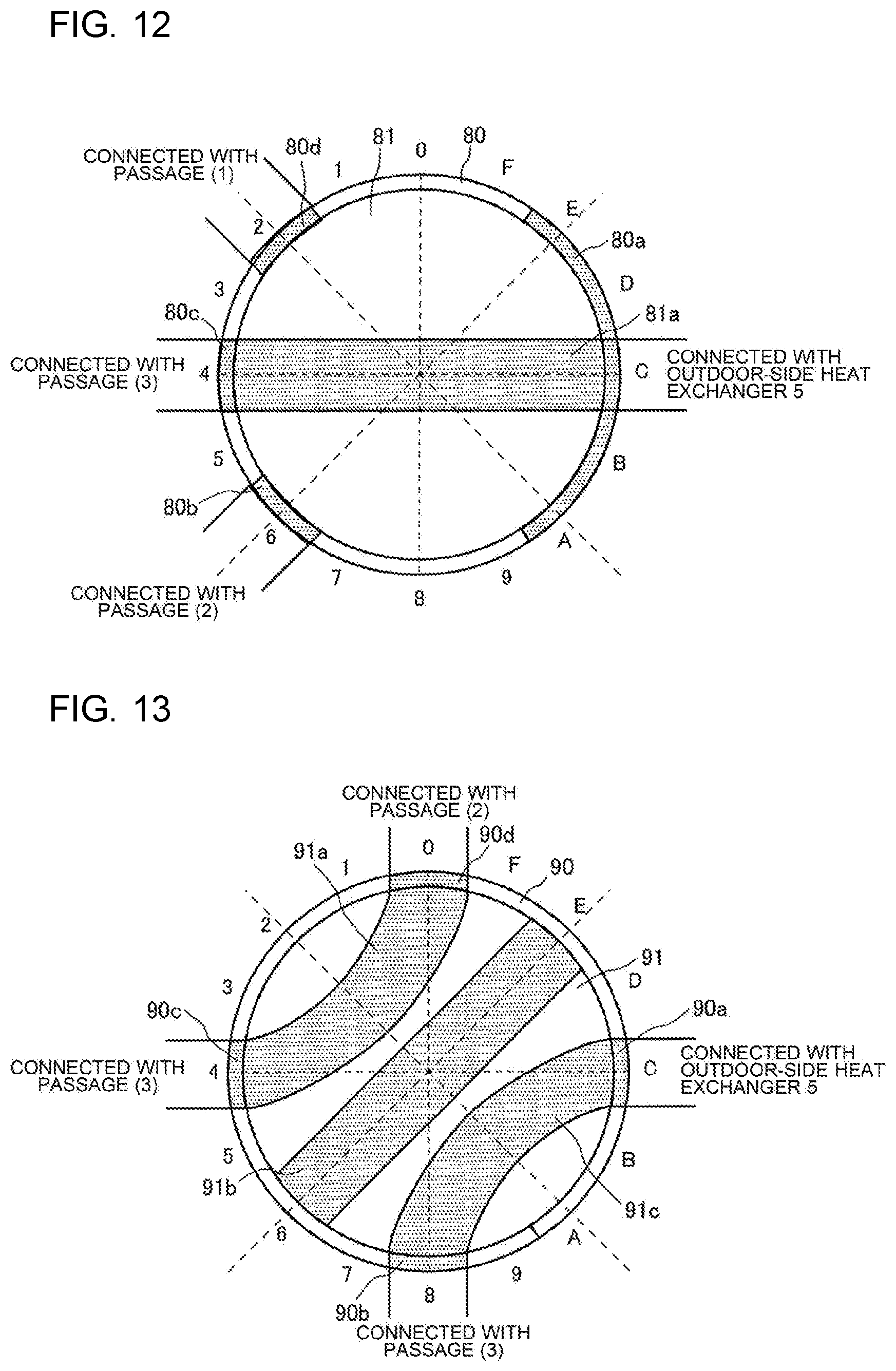
[0135] FIG. 12 is a diagram illustrating an example of the second flow switching device 9 of the heat pump system 100 according to Embodiment 3 of the present disclosure. FIG. 13 is a diagram illustrating another example of the second flow switching device 9 of the heat pump system 100 according to Embodiment 3 of the present disclosure. FIGS. 12 and 13 each schematically illustrate the second flow switching device 9 as viewed in a direction along the rotation axis.
[0136] As illustrated in FIG. 12, the second flow switching device 9 is, for example, a rotary valve having conductive portions, which are shaded as indicated in the figure, has a cylindrical shape, and includes an outer peripheral portion 80 and a cylindrical valve body 81. In the outer peripheral portion 80, connection apertures 80a to 80d are formed, and in the cylindrical valve body 81, a conduit 81a formed.
[0137] The connection aperture 80a is connected with the outdoor-side heat exchanger 5 by a refrigerant pipe 1, and the connection aperture 80b is connected with the first auxiliary heat exchanger 15 by a refrigerant pipe 1. The connection aperture 80c is connected with the second auxiliary heat exchanger 16 by a refrigerant pipe 1, and the connection aperture 80d is connected with the expansion device 8 by a refrigerant pipe 1.
[0138] Alternatively, as illustrated in FIG. 13, the second flow switching device 9 is, for example, a rotary valve having conductive portions, which are shaded as indicated in the figure, has a cylindrical shape, and includes an outer peripheral portion 90 and a cylindrical valve body 91. In the outer peripheral portion 90, connection apertures 90a to 90d are formed, and in the cylindrical valve body 91, conduits 91a to 91c are formed.
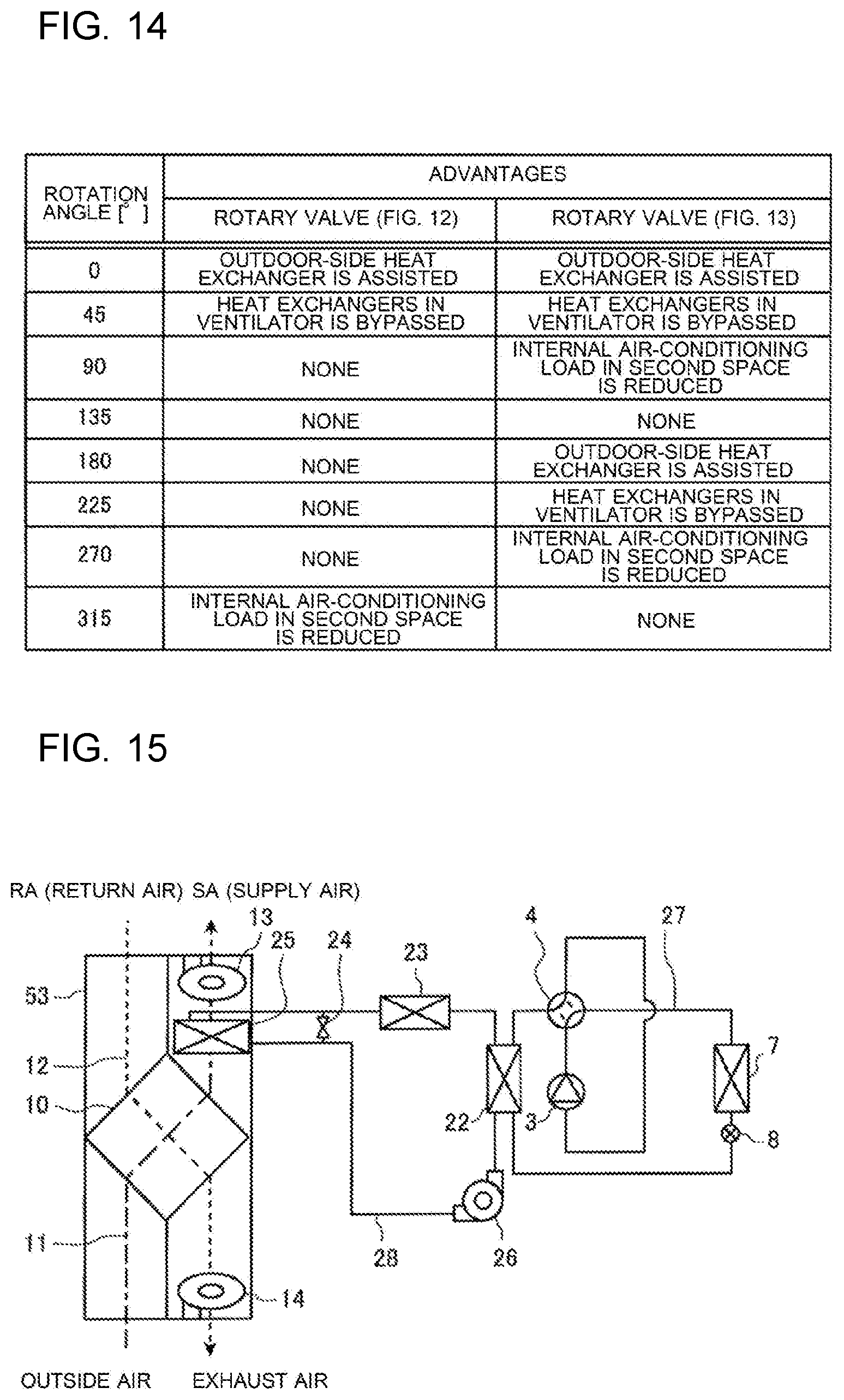
[0139] FIG. 14 illustrates examples of the operation of the second flow switching device 9 of the heat pump system 100 according to Embodiment 3 of the present disclosure. Specifically, FIG. 14 indicates a list of advantages (achievable operation modes) that are obtained in the case where rotation angles of the rotary valves are rotation angles indicated in the figure. In this case, it is assumed that the rotation angles of the rotary valves that are set as illustrated in FIGS. 12 and 13 are each a reference angle (0 degrees).
[0140] In the rotary valve as illustrated in FIG. 12, when the rotation angle of the cylindrical valve body 81 is the reference angle, the flow direction set by the second flow switching device 9 is the third direction, and the heat exchange at the outdoor-side heat exchanger 5 is assisted. When the cylindrical valve body 81 is rotated through an angle of 45 degrees from the reference angle in a clockwise direction, the flow direction set by the second flow switching device 9 is the first direction, and the refrigerant bypasses the first auxiliary heat exchanger 15 and the second auxiliary heat exchanger 16 installed inside the ventilator 53. When the cylindrical valve body 81 is rotated through an angle of 315 degrees from the reference angle in the clockwise direction (or an angle of 45 degrees in a counterclockwise direction), the flow direction set by the second flow switching device 9 is the second direction, and the internal air-conditioning load in the second space 102 is reduced.
[0141] In the rotary valve as illustrated in FIG. 13, when the rotation angle of the cylindrical valve body 91 is the reference angle, or the cylindrical valve body 91 is rotated through an angle of 180 degrees from the reference angle in the clockwise direction, the flow direction set by the second flow switching device 9 is the third direction, and the heat exchange at the outdoor-side heat exchanger 5 is assisted. When the cylindrical valve body 91 is rotated through an angle of 45 degrees or an angle of 225 degrees from the reference angle in the clockwise direction, the flow direction set by the second flow switching device 9 is the first direction, and the refrigerant bypasses the first auxiliary heat exchanger 15 and the second auxiliary heat exchanger 16 installed inside the ventilator 53. When the cylindrical valve body 91 is rotated through an angle of 90 degrees or an angle of 270 degrees from the reference angle in the clockwise direction, the flow direction set by the second flow switching device 9 is the second direction, and the internal air-conditioning load in the second space 102 is reduced.
[0142] In the heat pump system 100 according to Embodiment 3, the controller 54 causes the second flow switching device 9 to switch the flow passage for the refrigerant to the flow passage in which the refrigerant flows into the first auxiliary heat exchanger 15, when the following first condition is satisfied: the operation mode of the air-conditioning apparatus 40 that air-conditions the first space 101 is different from that of the air-conditioning apparatus 41 that air-conditions the second space 102; the compressor 3 of the air-conditioning apparatus 40 and the compressor (not illustrated) of the air-conditioning apparatus 41 are both in operation, and the ventilator 53 is in operation.
[0143] In the heat pump system 100 according to Embodiment 3, since the second flow switching device 9 is controlled in the above manner, exhaust heat from the air-conditioning apparatus 40 installed in the first space 101 can be used in the second space 102. It is therefore possible to reduce the internal air-conditioning load in the second space 102 and improve the energy efficiency of the heat pump system 100 to achieve energy savings.
[0144] In the heat pump system 100 according to Embodiment 3, when the first condition is satisfied and the outside air temperature is lower than or equal to the first temperature set in advance or higher than or equal to the second temperature set in advance and higher than the first temperature, the controller 54 causes the second flow switching device 9 to switch the flow passage for the refrigerant to the flow passage in which the refrigerant flows into the bypass 18.
[0145] If the operation of the refrigeration cycle is unstable, the heat pump system 100 according to Embodiment 3 can give priority to stabilization of the operation of the refrigeration cycle circuit.
Embodiment 4
[0146] Embodiment 4 of the present disclosure will be described. It should be noted that with respect to Embodiment 4, part of the above descriptions regarding Embodiments 1 to 3 that can also be applied to Embodiment 4 will not be repeated, and components that are the same as or equivalent to those in each of Embodiments 1 to 3 will be denoted by the same reference signs.
[0147] FIG. 15 is a first detailed configuration diagram of the heat pump system 100 according to Embodiment 4 of the present disclosure.
[0148] As illustrated in FIG. 15, in Embodiment 4, an auxiliary heat exchanger 25 is provided in part of the supply air passage 11 that is located between the total heat exchanger 10 and the supply air fan 13.
[0149] The heat pump system 100 includes a refrigerant circuit in which the compressor 3, the first flow switching device 4, the indoor-side heat exchanger 7, the expansion device 8, and a water heat exchanger 22 are sequentially connected by refrigerant pipes 27 to allow refrigerant to circulate. The heat pump system 100 also includes a water circuit in which the water heat exchanger 22, a heat-source-side heat exchanger 23, the auxiliary heat exchanger 25, and a pump 26 are sequentially connected by a water pipe 28 to allow water to circulate. In the water circuit, a bypass open/close valve 24 is provided in parallel with the auxiliary heat exchanger 25.
[0150] The water heat exchanger 22 causes refrigerant that flows in the refrigerant circuit to exchange heat with water that flows in the water circuit. The bypass open/close valve 24 is connected to both ends of the auxiliary heat exchanger 25 by the water pipe 28. When being in closed state, the bypass open/close valve 24 allows water to pass through the auxiliary heat exchanger 25. By contrast, when being in opened state, the bypass open/close valve 24 does not allow water to pass through the auxiliary heat exchanger 25. The heat-source-side heat exchanger 23 causes water that flows in the water circuit to exchange heat with air that flows in the indoor space.
[0151] The auxiliary heat exchanger 25 causes air that has passed through the total heat exchanger 10 to exchange heat with water. The auxiliary heat exchanger 25 is configured to cause air taken from the outdoor space into the ventilator 53 to pass through the total heat exchanger 10 and then pass through the auxiliary heat exchanger 25. Because of this configuration, priority is given to heat exchange of air that flows in the indoor space. It is therefore possible to ensure the comfortability of the indoor space and improve the energy efficiency of the air-conditioning apparatus 40 to achieve energy savings.
[0152] FIG. 16 is a second detailed configuration diagram of the heat pump system 100 according to Embodiment 4 of the present disclosure.
[0153] As illustrated in FIG. 16, the heat pump system 100 may be configured such that a plurality of refrigerant circuits and a plurality of water circuits are provided, and the water circuits are arranged in parallel with each other. Alternatively, the heat pump system 100 may be configured such that a plurality of indoor-side heat exchangers 7 and a plurality of expansion devices 8 are provided, and the indoor-side heat exchangers 7 are arranged in parallel with the expansion devices 8.
[0154] The second flow switching device 9 corresponds to "flow switching device" of the present disclosure, the air-conditioning apparatus 40 corresponds to "first air-conditioning apparatus" of the present disclosure, and the air-conditioning apparatus 41 corresponds to "second air-conditioning apparatus" of the present disclosure.
REFERENCE SIGNS LIST
[0155] 1 refrigerant pipe, 2 communication transmission line, 3 compressor, 4 first flow switching device, 5 outdoor-side heat exchanger, 6 outdoor fan, 7 indoor-side heat exchanger, 8 expansion device, 9 second flow switching device, 10 total heat exchanger, 11 supply air passage, 12 exhaust air passage, 13 supply air fan, 14 exhaust air fan, 15 first auxiliary heat exchanger, 16 second auxiliary heat exchanger, 17 outside-air temperature sensor, 18 bypass, 21 indoor fan, 22 water heat exchanger, 23 heat-source-side heat exchanger, 24 bypass open/close valve, 25 auxiliary heat exchanger, 26 pump, 27 refrigerant pipe, 28 water pipe, 40 air-conditioning apparatus, 41 air-conditioning apparatus, 51 indoor unit, 52 outdoor unit, 53 ventilator, 54 controller, 56 remote control unit, 80 outer peripheral portion 80a to 80d connection aperture, 81 cylindrical valve body, 81a conduit, 90 outer peripheral portion 90a to 90d connection aperture, 91 cylindrical valve body, 91a to 91d conduit, 100 heat pump system, 101 first space, 102 second space, 500 auxiliary heat exchanger unit
* * * * *
D00000
D00001
D00002
D00003
D00004
D00005
D00006
D00007
D00008
D00009
D00010
XML
uspto.report is an independent third-party trademark research tool that is not affiliated, endorsed, or sponsored by the United States Patent and Trademark Office (USPTO) or any other governmental organization. The information provided by uspto.report is based on publicly available data at the time of writing and is intended for informational purposes only.
While we strive to provide accurate and up-to-date information, we do not guarantee the accuracy, completeness, reliability, or suitability of the information displayed on this site. The use of this site is at your own risk. Any reliance you place on such information is therefore strictly at your own risk.
All official trademark data, including owner information, should be verified by visiting the official USPTO website at www.uspto.gov. This site is not intended to replace professional legal advice and should not be used as a substitute for consulting with a legal professional who is knowledgeable about trademark law.