Egg Container And A Method Of Removing One Or More Eggs From Said Egg Container
Schein; Brogan S. ; et al.
U.S. patent application number 16/599214 was filed with the patent office on 2020-06-25 for egg container and a method of removing one or more eggs from said egg container. This patent application is currently assigned to All About Packaging, Inc.. The applicant listed for this patent is All About Packaging, Inc.. Invention is credited to Eric S. Hamberger, Brogan S. Schein.
| Application Number | 20200198879 16/599214 |
| Document ID | / |
| Family ID | 71097310 |
| Filed Date | 2020-06-25 |


| United States Patent Application | 20200198879 |
| Kind Code | A1 |
| Schein; Brogan S. ; et al. | June 25, 2020 |
EGG CONTAINER AND A METHOD OF REMOVING ONE OR MORE EGGS FROM SAID EGG CONTAINER
Abstract
An egg container is disclosed which includes a hollow receptacle having a pair of sidewalls connected to a first end wall, to a second end wall, and to a bottom wall. The hollow receptacle has an open top surrounded by a rim. The rim has a pair of folded flanges formed thereon, each of which extends along at least a portion of the length of each of the pair of sidewalls. The hollow receptacle is capable of holding multiple eggs in a stationary and spaced apart fashion. The egg container further includes a lid sized and shaped to slide between the pair of folded flanges and completely cover the open top of the hollow receptacle. A method of removing one or more eggs from the egg container is also taught.
| Inventors: | Schein; Brogan S.; (Neenah, WI) ; Hamberger; Eric S.; (Menasha, WI) | ||||||||||
| Applicant: |
|
||||||||||
|---|---|---|---|---|---|---|---|---|---|---|---|
| Assignee: | All About Packaging, Inc. Appleton WI |
||||||||||
| Family ID: | 71097310 | ||||||||||
| Appl. No.: | 16/599214 | ||||||||||
| Filed: | October 11, 2019 |
Related U.S. Patent Documents
| Application Number | Filing Date | Patent Number | ||
|---|---|---|---|---|
| 62783304 | Dec 21, 2018 | |||
| Current U.S. Class: | 1/1 |
| Current CPC Class: | B65D 85/324 20130101; B65D 43/12 20130101; B65D 1/36 20130101; B65B 69/00 20130101; B65D 85/32 20130101 |
| International Class: | B65D 85/32 20060101 B65D085/32; B65D 1/36 20060101 B65D001/36; B65D 43/12 20060101 B65D043/12; B65B 69/00 20060101 B65B069/00 |
Claims
1. An egg container comprising: a) a hollow receptacle having a pair of sidewalls connected to a first end wall, to a second end wall, and to a bottom wall, said hollow receptacle having an open top surrounded by a rim, said rim having a pair of folded flanges formed thereon, each of which extends along at least a portion of the length of each of said pair of sidewalls, and said hollow receptacle capable of holding multiple eggs in a stationary and spaced apart fashion; and b) a lid sized and shaped to slide between said pair of folded flanges and completely cover said open top of said receptacle.
2. The egg container of claim 1 wherein said hollow receptacle is constructed from polyethylene terephthalate or polyethylene terephthalate with glycol.
3. The egg container of claim 2 wherein said hollow receptacle is molded from polyethylene terephthalate having a thickness of from between about 25 to about 35 millimeters.
4. The egg container of claim 1 wherein said pair of folded flanges is aligned parallel to one another.
5. The egg container of claim 1 wherein said open top of said hollow receptacle has a generally rectangular configuration, and said hollow receptacle has a height of at least about 2.5 inches.
6. The egg container of claim 1 wherein said lid is planar and has a first side, a second side, a first end and a second end, and said lid has a generally rectangular configuration.
7. The egg container of claim 6 wherein each of said pair of folded flanges has an upper surface, and said rim includes a pair of spaced apart upward extending protrusions formed above said second end wall, and each of said pair of upward extending protrusions extends above said upper surface of each of said pair of folded flanges, and said lid has a pair of apertures formed therethrough adjacent to said second end which corresponds with said pair of upward extending protrusions, and as said lid is slide between said pair of folded flanges and covers said open top of said hollow receptacle, said pair of apertures engage with said pair of upwardly extending protrusions and lock said lid to said hollow receptacle.
8. The egg container of claim 1 wherein said lid is constructed from paperboard.
9. The egg container of claim 8 wherein said paperboard has a thickness ranging from between about 0.01 inches to about 0.02 inches.
10. An egg container comprising: a) a hollow receptacle having a pair of sidewalls connected to a first end wall, to a second end wall, and to a bottom wall, said hollow receptacle having an open top surrounded by a rim, said rim having a pair of folded flanges formed thereon, each of which extends along at least a portion of the length of each of said pair of sidewalls, said pair of folded flanges having an upper plane, and said rim includes a pair of spaced apart upwardly extending protrusions formed above said second end wall, and each of said pair of spaced apart upwardly extending protrusions extends above said upper surface of said pair of folded flanges, and said hollow receptacle is capable of holding multiple eggs in a stationary and spaced apart fashion; and b) a lid having a first side, a second side, a first end and a second end, and said lid having a generally rectangular configuration, said lid having a pair of apertures formed therethrough adjacent to said second end which corresponds with said pair of upwardly extending protrusions, and as said lid is slid between said pair of folded flanges it covers said open top of said hollow receptacle, and said pair of apertures engage with said pair of spaced apart upwardly extending protrusions to lock said lid to said hollow receptacle.
11. The egg container of claim 10 wherein said hollow receptacle is constructed of a recyclable, clear plastic material.
12. The egg container of claim 10 wherein said hollow receptacle has stacking nubs formed in said bottom wall.
13. The egg container of claim 10 wherein said hollow receptacle can nest with another hollow receptacle thereby saving floor space at a packaging site.
14. The egg container of claim 10 wherein said rim contains a third upwardly extending protrusion positioned above said second end wall, and said third upwardly extending protrusion stops said lid from sliding past said second end wall.
15. The egg container of claim 14 wherein said third upwardly extending protrusion is positioned between said pair of spaced apart upwardly extending protrusions.
16. The egg container of claim 10 wherein said lid is constructed from cardboard and can be printed.
17. An egg container comprising: a) a hollow receptacle having a pair of sidewalls connected to a first end wall, to a second end wall, and to a bottom wall, said hollow receptacle having an open top surrounded by a rim, said rim having a pair of folded flanges formed thereon, each of which extends along at least a portion of the length of each of said pair of sidewalls, said pair of folded flanges having an upper plane, and said rim includes a pair of spaced apart upwardly extending protrusions formed above said second end wall and a third upwardly extending protrusion formed between said pair of spaced apart upwardly extending protrusions, each of said pair of spaced apart upwardly extending protrusions and said third upwardly extending protrusion extends above said upper surface of said pair of folded flanges, and said hollow receptacle is capable of holding at least twelve eggs in a stationary and spaced apart fashion; and b) a lid having a first side, a second side, a first end and a second end, and said lid having a generally rectangular configuration, said lid having a pair of apertures formed therethrough adjacent to said second end which corresponds with said pair of upwardly extending protrusions, and as said lid is slid between said pair of folded flanges and covers said open top of said hollow receptacle, said pair of apertures engage with said pair of spaced apart upwardly extending protrusions to lock said lid to said hollow receptacle, and said third upwardly extending protrusion stops said lid from sliding past said second end wall.
18. The egg container of claim 16 wherein each of said pair of spaced apart upwardly extending protrusions has a ramp configuration.
19. The egg container of claim 16 wherein each of said pair of spaced apart upwardly extending protrusions and said third upwardly extending protrusion terminate in a respective plane.
20. A method of removing one or more eggs from an egg container after said egg container has been filled with multiple eggs, said egg container including a hollow receptacle having a pair of sidewalls connected to a first end wall, to a second end wall, and to a bottom wall, said hollow receptacle having an open top surrounded by a rim, said rim having a pair of folded flanges formed thereon, each of which extends along at least a portion of the length of each of said pair of sidewalls, said pair of folded flanges having an upper plane, and said rim includes a pair of spaced apart upwardly extending protrusions formed above said second end wall, and each of said pair of spaced apart upwardly extending protrusions extends above said upper surface of said pair of folded flanges, and said hollow receptacle is capable of holding said multiple eggs in a stationary and spaced apart fashion; and a lid sized and shaped to slide between said pair of folded flanges and completely cover said open top of said receptacle, said lid having a pair of apertures formed therethrough adjacent to said second end which corresponds with said pair of spaced apart upwardly extending protrusions, and as said lid is slid between said pair of folded flanges it covers said open top of said hollow receptacle, and said pair of apertures engage with said pair of upwardly extending protrusions to lock said lid to said hollow receptacle, said method comprising the steps of: a) sliding said lid in a direction away from said second end wall a sufficient distance to expose one or more eggs; and b) turning said egg container upside down to allow said one or more exposed eggs to fall out into a person's hand.
21. The method of claim 19 further comprising sliding said lid towards said second end wall of said receptacle; and allowing said pair of apertures to again engage with said pair of spaced apart upwardly extending protrusions to close said open top and lock said lid to said hollow receptacle.
Description
FIELD OF THE INVENTION
[0001] This invention relates to an egg container and a method of removing one or more eggs from the egg container.
BACKGROUND OF THE INVENTION
[0002] Today, eggs are typically packaged in cardboard or Styrofoam.TM. containers which usually can hold twelve or eighteen eggs. Styrofoam is a trademark used for a light resilient polystyrene plastic. Styrene is a colorless oily liquid, C.sub.6H.sub.5CH:CH.sub.2, the monomer of polystryene. Polystyrene is a rigid clear thermoplastic polymer that can be molded into objects or be made into a foam used in packaging. The egg cartons are filled with standard size eggs and are placed in coolers for sale in various food stores, grocery stores and supermarkets. Most such egg cartons consist of a clam shell design having an upper portion hinged to a lower portion. The upper portion can swing open at the hinge line to expose the eggs contained in the lower portion. The materials from which these egg cartons are manufactured completely hide the eggs from view when the egg cartons are closed. In order for a prospective purchaser to view the eggs therein, to see if any of the eggs are cracked or broken, he or she has to physically open the egg carton. This is an inconvenience to many purchasers. In addition, many of these clam shell cartons exhibit weak points in their construction. They are especially prone to side pressures which can cause the egg carton to open and can cause one or more of the eggs housed therein to be damaged or cracked during transport and storage. Broken and cracked eggs mean less profit to the grocery store. A third disadvantage with current egg cartons is that they cannot be easily printed and when they are printed, the print quality is usually poor and exhibits low resolution. This distracts from brand recognition and limits the ability of the vendor to cross sell complementary products.
[0003] Now, an improved egg container has been invented which visibly displays the eggs contained therein and which is not susceptible to egg breakage due to side pressures exerted thereon. In addition, this improved egg container can be easily printed in high resolution and/or in multiple colors. A method of removing one or more eggs from the egg container is also disclosed.
SUMMARY OF THE INVENTION
[0004] Briefly, this invention relates to an egg container and a method of removing one or more eggs from the egg container. In one embodiment, the egg container includes a hollow receptacle having a pair of sidewalls connected to a first end wall, to a second end wall, and to a bottom wall. The hollow receptacle has an open top surrounded by a rim. The rim has a pair of folded flanges formed thereon, each of which extends along at least a portion of each of the pair of sidewalls. The hollow receptacle is capable of holding multiple eggs in a stationary and spaced apart fashion. The egg container further includes a lid sized and shaped to slide between the pair of folded flanges and completely cover the open top of the receptacle.
[0005] In a second embodiment, the egg container includes a hollow receptacle having a pair of sidewalls connected to a first end wall, to a second end wall, and to a bottom wall. The hollow receptacle has an open top surrounded by a rim. The rim has a pair of folded flanges formed thereon, each of which extends along at least a portion of each of the pair of sidewalls. The pair of folded flanges have an upper surface, and the rim includes a pair of spaced apart upwardly extending protrusions formed above the second end wall. Each of the pair of upwardly extending protrusions extends above the upper surface of the pair of folded flanges. The hollow receptacle is capable of holding multiple eggs in a stationary and spaced apart fashion. The egg container further includes a lid having a first side, a second side, a first end and a second end and has a generally rectangular configuration. The lid has a pair of apertures formed therethrough, adjacent to the second end, which corresponds with the pair of upwardly extending protrusions. As the lid is slid between the pair of folded flanges it covers the open top of the hollow receptacle, and the pair of apertures engage with the pair of upwardly extending protrusions to lock the lid to the hollow receptacle.
[0006] In a third embodiment, the egg container includes a hollow receptacle having a pair of sidewalls connected to a first end wall, to a second end wall, and to a bottom wall. The hollow receptacle has an open top surrounded by a rim. The rim has a pair of folded flanges formed thereon, each of which extends along at least a portion of each of the pair of sidewalls. The pair of folded flanges has an upper surface. The rim includes a pair of spaced apart upwardly extending protrusions formed above the second end wall and a third upwardly extending protrusion formed between the pair of upwardly extending protrusions. Each of the pair of upwardly extending protrusions and the third upwardly extending protrusion extends above the upper surface of the pair of folded flanges, and the hollow receptacle is capable of holding at least twelve eggs in a stationary and spaced apart fashion. The egg container further includes a lid having a first side, a second side, a first end and a second end, and has a generally rectangular configuration. The lid has a pair of apertures formed therethrough, adjacent to said second end, which corresponds with the pair of upwardly extending protrusions. As the lid is slid between the pair of folded flanges and covers the open top of the hollow receptacle, the pair of apertures engages with the pair of upwardly extending protrusions to lock the lid to the hollow receptacle, and the third upwardly extending protrusion stops the lid from sliding past the second end wall.
[0007] A method of removing one or more eggs from an egg container after the egg container has been filled with multiple eggs, is also taught. The egg container includes a hollow receptacle having a pair of sidewalls connected to a first end wall, to a second end wall, and to a bottom wall. The hollow receptacle has an open top surrounded by a rim. The rim has a pair of folded flanges formed thereon, each of which extends along at least a portion of each of the pair of sidewalls. The hollow receptacle is capable of holding multiple eggs in a stationary and spaced apart fashion. The egg container further includes a lid sized and shaped to slide between the pair of folded flanges and completely cover the open top of the receptacle. The method includes the steps of sliding the lid in a direction away from the second end wall a sufficient distance to expose one or more eggs. The egg container is then turned upside down to allow the one or more exposed eggs to fall out into a person's hand.
[0008] The general object of this invention is to provide an egg container. A more specific object of this invention is to provide an egg container which visibly displays the eggs housed therein.
[0009] Another object of this invention is to provide an egg container that does not require a hinge.
[0010] A further object of this invention is to provide an egg container formed from two distinct members, each of which can be recycled.
[0011] Still another object of this invention is to provide an egg container which includes a receptacle which can be nested and stacked with like receptacles, prior to being filled with eggs at a packaging site, thereby saving floor space.
[0012] Still further, an object of this invention is to provide a method of removing one or more eggs from the egg container.
[0013] Still another object of this invention is to provide an egg container that can be printed in high resolution and/or in multiple colors.
[0014] Other objects and advantages of the present invention will become more apparent to those skilled in the art in view of the following description and the accompanying drawings.
BRIEF DESCRIPTION OF THE DRAWINGS
[0015] FIG. 1 is a perspective view of an egg container which includes a receptacle and a movable lid.
[0016] FIG. 2 is a perspective view of the receptacle shown in FIG. 1 which is capable of holding six eggs in a stationary and spaced apart fashion.
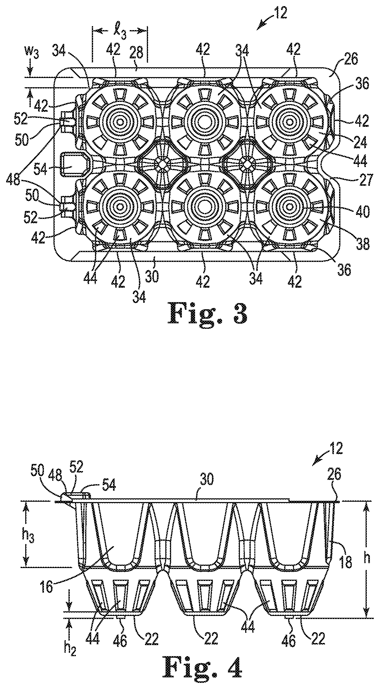
[0017] FIG. 3 is a top view of the receptacle shown in FIG. 2.
[0018] FIG. 4 is a side view of the receptacle shown in FIG. 2.
[0019] FIG. 5 is an end view of the receptacle shown in FIG. 2.
[0020] FIG. 6 is a top view of the egg container shown in FIG. 1 depicting the lid closing the open top of the receptacle.
[0021] FIG. 7 is a side view of the egg container shown in FIG. 6 showing the presence of the lid.
[0022] FIG. 8 is an end view of the egg container shown in FIG. 6 showing the presence of the lid.
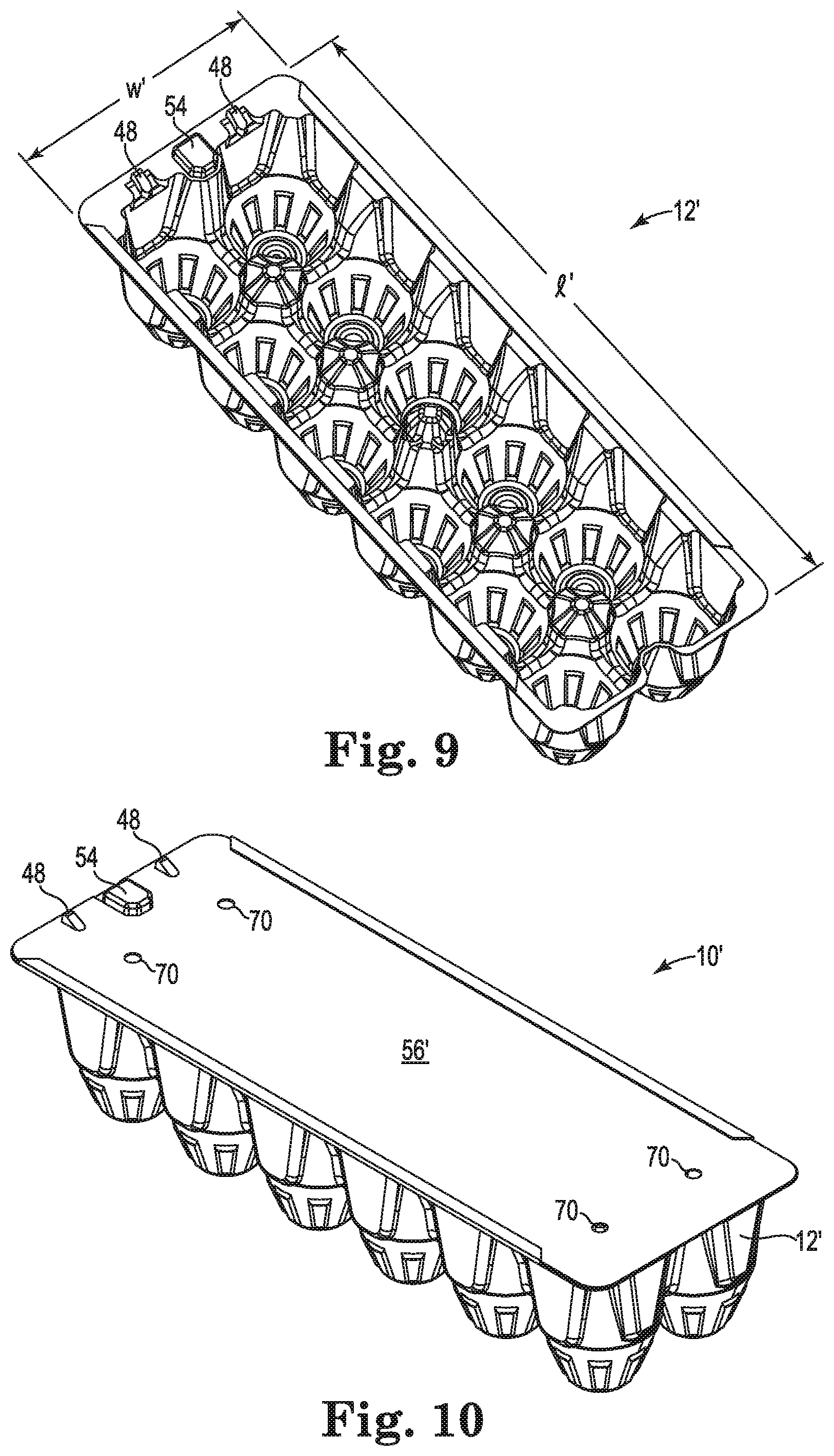
[0023] FIG. 9 is a perspective view of a receptacle capable of holding twelve eggs.
[0024] FIG. 10 is a perspective view of the receptacle shown in FIG. 9 having a lid attached.
[0025] FIG. 11 is a perspective view of a receptacle capable of holding eighteen eggs.
[0026] FIG. 12 is a perspective view of the receptacle shown in FIG. 11 having a lid attached.
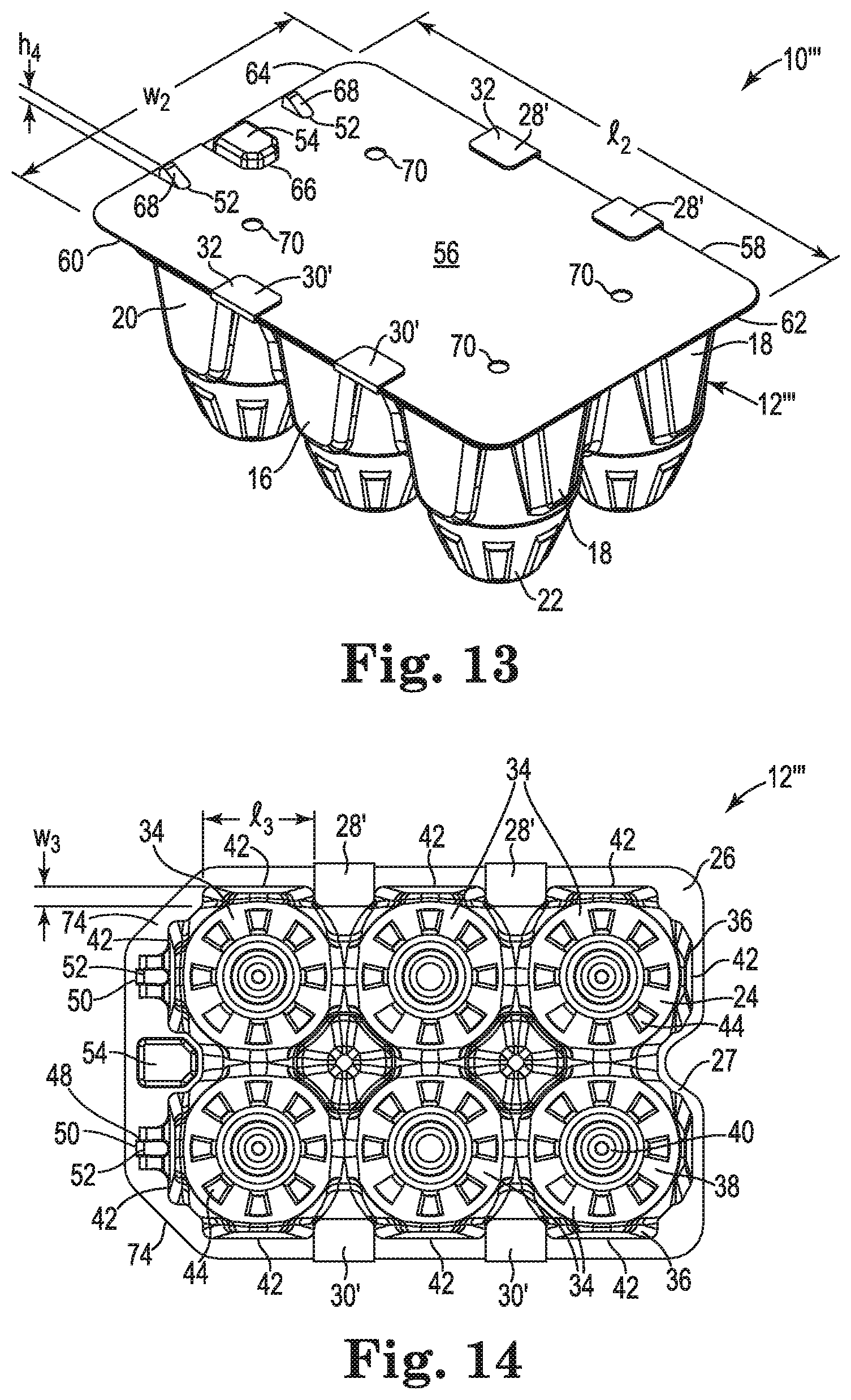
[0027] FIG. 13 is a perspective view of an alternative egg container which includes a receptacle and a movable lid.
[0028] FIG. 14 is a top view of the receptacle shown in FIG. 13 without the lid.
DETAILED DESCRIPTION OF THE INVENTION
[0029] Referring to FIG. 1, an egg container 10 is shown. By "container" it is meant a receptacle having raised sides and a bottom used for holding or displaying articles. The egg container 10 is capable of retaining and holding one or more eggs in a stationary and spaced apart fashion, By "stationary" it is meant not moving, unchanging, By "spaced apart" it is meant that one egg does not physically touch or contact another egg. The egg container 10 is designed to hold the eggs in such a fashion that breaking or cracking of the eggs will be reduced during storage, transport, while being displayed for sale in a cooler at a grocery store, and while retained in a consumer's refrigerator after being purchased from a retail store. The egg container 10 can hold multiple eggs. By "multiple" it is meant consisting of more than one individual egg. By "egg" it is meant the round or oval reproductive body of various animals, consisting usually of an embryo surrounded by nutrient material and a protective covering. A bird's egg especially that of a hen, is commonly used as food by humans. Commonly, four, six, twelve or eighteen eggs are retained in an egg container 10, However, the egg container 10 can be sized to hold any number of eggs. For example, the egg container 10 can hold as few as four eggs, or as many as thirty eggs.
[0030] Referring to FIGS. 1-5, the egg container 10 includes a hollow receptacle 12. By "hollow receptacle" it is meant a container that holds items or matter. The hollow receptacle 12, best shown in FIG. 2, is a one-piece structure. The hollow receptacle 12 is capable of holding multiple eggs in a stationary and spaced apart fashion. The hollow receptacle 12 can vary in size, shape and configuration. The hollow receptacle 12 has a length l, a width w and a height h, see FIGS. 2 and 4. The length l, the width w and the height h of the hollow receptacle 12 can all vary depending upon the number of eggs one wishes to retain in the egg container 10. For example, for an egg container 10 which can retain six large size eggs, the hollow receptacle 12 can have a length l of about 6.3 inches, a width w of about 4.25 inches and a height h of about 2.7 inches. For an egg container 10 which can retain twelve large size eggs, the hollow receptacle 12 can have a length l of about 12.5 inches, a width w of about 4.25 inches and a height h of about 2.7 inches. For an egg container 10 which can retain eighteen large size eggs, the hollow receptacle 12 can have a length l of about 12.5 inches, a width w of about 6.5 inches and a height h of about 2.7 inches. An egg container 10 designed to hold "large eggs" can also hold "extra large eggs" without necessitating an increase in overall dimensions.
[0031] The hollow receptacle 12 can be formed or molded from various plastic materials. Desirably, the hollow receptacle 12 is molded. The hollow receptacle 12 should be constructed from a clear and/or transparent material, such that the eggs retained therein are visible to a potential purchaser. A desired material from which the hollow receptacle 12 can be formed is polyethylene terephthalate (PET). PET is the chemical name for polyester. PET is a clear, strong, and lightweight plastic that is widely used for packaging foods and beverages, especially convenience-sized soft drinks, juices and water. The basic building blocks of PET are ethylene glycol and terephthalic acid, which are combined to form a polymer chain. The resulting spaghetti-like strands of PET are extruded, quickly cooled, and cut into small pellets. The resin pellets are then heated to a molten liquid that can be easily extruded or molded into items of practically any shape.
[0032] PET was first synthesized in North America in the mid-1940s by DuPont chemists searching for new synthetic fibers. DuPont later branded its PET fiber as "Dacron". Today, more than half of the world's synthetic fiber is made from PET, which is called "polyester" when used for fiber or fabric applications. When used for containers and other purposes, it is called PET or PET resin.
[0033] It should be understood that other thermoplastic materials, known to those skilled in the art, can also be used. These include but are not limited to: polyolefins, including polyethylene, polypropylene or variations thereof. Polyethylene is a polymerized ethylene resin, used especially for containers, kitchenware, and tubing or in the form of films and sheets for packaging. Polypropylene is any of various thermoplastic resins that are polymers of polypropylene and are used to make molded articles and fibers. However, when using polyethylene or polypropylene, one should make sure that they are polymerized to produce a clear plastic.
[0034] Other thermoplastic materials that can also be used include polyethylene terephthalate with glycol (PETG), polyvinyl (PV) and polyvinyl chloride (PVC). Polyethylene terephthalate with glycol (PETG) is of the same chemical composition as PET but with the addition of glycol. With just this one addition, the chemical composition is completely changed, creating a whole new plastic. The addition of glycol to create PETG removes the hazing effect seen during heating and also prevents an undesirable crystallization effect that causes standard PET to become brittle. Additionally, the inclusion of glycol in this plastic will transform the outer walls of a bottle into a softer and more pliable material, making it easier and more comfortable to grip.
[0035] Polyvinyl (PV) designates any of a group of polymerized thermoplastic vinyls, including polyvinyl chloride (PVC). Polyvinyl chloride (PVC) is a solid plastic made from vinyl chloride. It is made softer and more flexible by the addition of phthalates, and can contain traces of bisphenol A (BPA).
[0036] Recyclable thermoplastic materials can also be used. Such recyclable thermoplastics include, but are not limited to: recyclable PET, recyclable PETG, recyclable polyvinyl (PV), recyclable PVC, as well as other recyclable plastics known to those skilled in the art.
[0037] Referring to FIGS. 4 and 5, the hollow receptacle 12 has a pair of sidewalls, 14 and 16, see FIG. 5, connected to a first end wall 18, to a second end wall 20, and to a bottom wall 22, see FIGS. 4 and 5. The pair of sidewalls 14 and 16, the first end wall 18, the second end wall 20, and the bottom wall 22 can have the same thickness or be of different thicknesses, Desirably, the pair of sidewalls 14 and 16, the first end wall 18, the second end wall 20, and the bottom wall 22 will be formed to approximately the same thickness. It has been found that a thickness ranging from between about 25 millimeters (ml) to about 35 ml works well. Desirably, the thickness of the pair of sidewalls 14 and 16, the first end wall 18, the second end wall 20, and the bottom wall 22 will be less than about 35 ml. More desirably, the thickness of the pair of sidewalls 14 and 16, the first end wall 18, the second end wall 20, and the bottom wall 22 will be less than about 33 mL Even more desirably, the thickness of the pair of sidewalls 14 and 16, the first end wall 18, the second end wall 20, and the bottom wall 22 will be less than about 30 ml. Still more desirably, the thickness of the pair of sidewalls 14 and 16, the first end wall 18, the second end wall 20, and the bottom wall 22 will be less than about 28 ml.
[0038] It should be understood that the thickness of the pair of sidewalls 14 and 16, the first end wall 18, the second end wall 20, and the bottom wall 22 can vary over each particular surface area. The thickness does not need to be uniform over the entire surface area, if desired. For example, the thickness of the pair of sidewalls 14 and 16, and the first end wall 18, the second end wall 20, could vary over the height h, see FIG. 4, Desirably, the thickness of the pair of sidewalls 14 and 16, the first end wall 18, the second end wall 20, and the bottom wall 22 will be uniform.
[0039] Referring to FIG. 2, the hollow receptacle 12 has an open top 24 which is surrounded by a rim 26, The open top 24 can be formed or molded to any known geometrical shape or configuration. Desirably, the open top 24 has a generally rectangular configuration. The size of the opening which forms the open top 24 can also vary. For example, for a hollow receptacle 12 which is designed to hold and retain six eggs, the open top 24 can range from about 6.2 inches by 4.1 inches.
[0040] Referring again to FIGS. 2 and 3, the size and shape of the rim 26 can vary. The rim 26 does not need to exhibit a uniform width around the periphery of the hollow receptacle 12. The rim 26 includes a finger indentation 27 located adjacent to the first end wall 18. The finger indentation 27 can be a notch, a cutout or a blank space formed in the rim 26, adjacent to the first end wall 18. The finger indentation 27 can vary in size, shape and configuration. The finger indentation 27 should be sized to allow the tip of a person's thumb and the tip of a person's index finger to easily be positioned within the finger indentation 27, The finger indentation 27 can be situated midway between the pair of sidewalls 14 and 16. Alternatively, the finger indentation 27 could be located closer to either of the pair of sidewalls 14 and 16, if desired. The width of the rim 26 around the periphery of the hollow receptacle 12 can vary to accommodate a locking mechanism, which will be explained later. The width of the rim 26 can range from between about 0.1 inches to about 1.0 inches around the periphery of the hollow receptacle 12.
[0041] Desirably, the rim 26 is planar except for the presence of a pair of folded flanges, 28 and 30. By "planar" it is meant of or relating to, or situated in a plane, being relatively flat having a two-dimensional quality. Each of the pair of folded flanges, 28 and 30, formed on the rim 26, extends along at least a portion of the length l of the hollow receptacle 12. By "folded flange" it is meant a folded protruding rim, edge, rib or collar used to receive another object that can slide within the fold. The pair of folded flanges, 28 and 30, is aligned above the pair of sidewalls 14 and 16, see FIG. 2. Each of the pair of folded flanges, 28 and 30, has a length l.sub.1 and a width w.sub.1. The length l.sub.1 and the width w.sub.1 can vary. For example, for a hollow receptacle 12 having a length l of about 6.3 inches, each of the folded flanges 28 and 30 can have a length l.sub.1 ranging from between about 2 inches to about 4.25 inches. The width w.sub.1 of each of the pair of folded flanges, 28 and 30, can be about 0.15 inches or less. Desirably, the width w.sub.1 of each of the pair of folded flanges, 28 and 30, can be about 0.125 inches or less. More desirably, the width w.sub.1 of each of the pair of folded flanges, 28 and 30, can be about 0.1 inches or less. Even more desirably, the width w.sub.1 of each of the pair of folded flanges, 28 and 30, can be at least about 0.05 inches. Most desirably, the width w.sub.1 of each of the pair of folded flanges, 28 and 30, can range from between about 0.05 inches to about 0.15 inches.
[0042] The pair of folded flanges, 28 and 30, can be aligned parallel to one another or be formed at an angle relative to one another. Desirably, the pair of folded flanges, 28 and 30, is aligned parallel to one another. Each of the pair of folded flanges, 28 and 30, can be linear in configuration, as is clearly shown in FIGS. 1 and 2. Alternatively, one or both of the pair of folded flanges, 28 and 30, can have a non-linear profile. For example, one or both of the pair of folded flanges, 28 and 30, can have an arcuate, curved or scalloped appearance. By "scallop" it is meant one of a series of curved or arcuate projections forming an ornamental border.
[0043] Referring again to FIG. 5, each of the pair of folded flanges 28 and 30 has an upper surface 32 which is located above the rim 26. Each of the upper surfaces 32, 32 can be situated at a distance d above the rim 26. The distance d can vary in dimension. Desirably, the distance d is about 0.15 inches or less. More desirably, the distance d is about 0.1 inches or less. Even more desirably, the distance d is about 0.08 inches or less. Most desirably, the distance d ranges from between about 0.05 inches to about 0.15 inches.
[0044] Again referring to FIG. 2, each of the pair of folded flanges, 28 and 30, is spaced away from the first end 18 of the receptacle 12 by a distance d.sub.1. The distance d.sub.1 can vary in dimension. For a six egg receptacle 12, having a length l of about 6.3 inches, the distance d.sub.1 can be about 1 inch or less. The reason for this setback will be explained shortly.
[0045] The opposite end of each of the pair of folded flanges, 28 and 30, can terminate approximate the second end 20 of the receptacle 12. Alternatively, the opposite end of each of the pair of folded flanges, 28 and 30, can terminate short of or be spaced apart from the second end 20 of the receptacle 12. In FIG. 2, the opposite end of each of the pair of folded flanges, 28 and 30, terminates just short of the second end 20 of the receptacle 12.
[0046] Referring now to FIGS. 2-5, the hollow receptacle 12 is constructed such that it can easily nest with a like hollow receptacle 12. The ability to nest multiple receptacles 12 after they are molded and prior to being filled with eggs can greatly reduce needed storage space, transportation cost and space needed at the vendor's plant as the egg containers are waiting to be filled with eggs, Proper nesting can also increase the number of receptacles 12 stacked on a skid in preparation to be shipped to the vendor.
[0047] Still referring to FIGS. 2-5, the hollow receptacle 12 includes multiple egg cavities 34. Six egg cavities 34 are shown in FIGS. 2-5. Each egg cavity 34 is sized and shaped to receive an egg (not shown). An egg has a generally oval shape with one end being slightly narrower than the opposite end. By "oval" it is meant an elliptical form or figure, resembling an egg in shape. Normally, the narrower end of each egg is inserted downward into each egg cavity 34. Each egg cavity 34 has an upper inside portion 36, a lower inside portion 38, and a bottom inside surface 40. The upper inside portion 36 and the lower inside portion 38 can vary in configuration. As depicted, the upper inside portion 36 can have a generally square shape while the lower inside portion 38 has a conical shape. By "conical" it is meant relating to or shaped like a cone. This conical configuration is slightly narrower than the profile of an egg which would be inserted therein. This arrangement means that the narrower end of the egg will be spaced away from the bottom inside surface 40 of the receptacle 12. The distance from the bottom of each egg to the bottom inside surface 40 of the receptacle 12 can vary. Desirably, this distance is about 0.25 inches or less. More desirably, this distance is about 0.20 inches or less. Even more desirably, this distance is about 0.15 inches or less. Most desirably, this distance ranges from between about 0.05 inches to about 0.25 inches. The air space between the narrower end of the egg and the bottom inside surface 40 of the receptacle 12 provides safety for the eggs and in the instance where weight happens to be vertically imposed upon the egg container 10, the hollow receptacle 12 would compress while leaving the eggs unscathed. The air space functions as an impact bumper. By preventing each egg from physically contacting the bottom inside surface 40, one can decrease the number of eggs which may become cracked or broken.
[0048] Referring again to FIGS. 2 and 3, each egg cavity 34 also includes at least one bump out 42. The size, shape and configuration of each bump out 42 can vary. Normally, all of the bump outs 42, 42 are of the same size and configuration. Each bump out 42 is formed adjacent to a side or end of the upper inside portion 36 of each of the egg cavities 34. The bump out 42 creates a space by moving a portion of the side walls, 14 and 16, and a portion of the first end wall 18 and the second end wall 20, outward away from the center of the hollow receptacle 12. Each of the bump outs 42, 42 adds structural rigidity to the hollow receptacle 12. This added structural rigidity increases the side strength and end strength of the hollow receptacle 12. The bump outs 42, 42 increase the ability of the hollow receptacle's 12 to handle sideward forces and end forces that could be exerted on the egg container 10. This protects the eggs from side impact and end impact. In addition, each of the bump outs 42, 42 provides space for a consumer to reach into the open top 24 of the hollow receptacle 12, with his or her thumb and one or more fingers, and readily grasp and remove an egg from the egg container 10.
[0049] Still referring to FIGS. 2 and 3, one can clearly see that the egg cavities 34, 34 located at each corner of the hollow receptacle 12 will have two bump outs 42, 42. The two bump outs 42, 42 are perpendicularly aligned relative to one another. The combination of these two bump outs 42, 42, so aligned, provide for very rigid corners on the hollow receptacle 12.
[0050] Referring again to FIGS. 2-4, the size, shape and configuration of each of the bump outs 42, 42 can vary. Desirably, each of the bump outs 42, 42 has the same overall shape and dimensions. As shown in FIGS. 3 and 4, each of the bump outs 42 has a length l.sub.3, a width w.sub.3 and a height h.sub.3, The length l.sub.3, the width w.sub.3 and the height h.sub.3 can all vary. For the egg container 10 shown in FIGS. 2-4, the length l.sub.3 can be about 1.2 inches or less, the width w.sub.3 can be about 0.35 inches or less, and the height h.sub.3 can be about 1.5 inches or less.
[0051] Still referring to FIGS. 2-5, the lower inside portion 38 of each egg cavity 34 also includes a plurality of spaced apart ribs 44. The number of ribs 44 utilized can vary. Likewise, the configuration of each of the ribs 44 can vary. In FIGS. 2-5, eight vertically oriented ribs 44 are equally spaced around the conical lower inside portion 38. In other words, each rib 44 is spaced 45 degrees from an adjacent rib 44. The size and shape of each of the ribs 44 can vary. The plurality of vertically oriented ribs 44, 44 add structural integrity to the lower inside portion 38 of each of the egg cavities 34, 34. In fact, the plurality of vertically oriented ribs 44, 44 practically make the conical lower inside portion 38 crush resistant. This design provides superior strength to the lower inside portion 38 of each of the egg cavities 34, 34 and reduces the chance that an egg positioned in each of the egg cavities 34, 34 will become broken or cracked during storage or transport.
[0052] It should be noted that in FIGS. 2-5, each of the ribs 44, 44 is visible on the exterior surface of the hollow receptacle 12, as well.
[0053] Referring now to FIGS. 1, 3, 4 and 5, the hollow receptacle 12 also includes one or more stacking nubs 46, 46. Desirably, four stacking nubs 46, 46, 46 and 46 are formed in the bottom wall 22 of the hollow receptacle 12 adjacent to each corner of the hollow receptacle 12, Each stacking nub 46 is axially aligned with the center of an egg cavity 34 which is located at a corner of the hollow receptacle 12, Those egg cavities 34, 34 situated away from a corner of the hollow receptacle 12 do not need to include a stacking nub 46. Each stacking nub 46 can be formed or molded as the hollow receptacle 12 is being formed or molded. Each stacking nub 46 is integral with the bottom wall 22 of the hollow receptacle 12 and extends downward therefrom. Each stacking nub 46 has a height h.sub.2, see FIG. 4. The height h.sub.2 can vary in dimension. The height h.sub.2 of each stacking nub 46 should be the same. The height h.sub.2 of each stacking nub 46 can be about 0.1 inches or less, Desirably, the height h.sub.2 of each stacking nub 46 can be about 0.09 inches or less. More desirably, the height h.sub.2 of each stacking nub 46 can be about 0.08 inches or less. Even more desirably, the height h.sub.2 of each stacking nub 46 can be about 0.05 inches or less. Most desirably, the height h.sub.2 of each stacking nub 46 can range from between about 0.01 inches to about 0.1 inches.
[0054] The presence of the stacking nubs 46, 46, 46 and 46 is optional and they could be eliminated, if desired. However, when present, the four stacking nubs 46, 46, 46 and 46 on each hollow receptacle 12 facilitate stacking one egg container 10, when filled, on top of another filled egg container 10. The stacking nubs 46, 46, 46 and 46 provide for a secure, non-skid fit with another filled egg container 10. The stacking nubs 46, 46, 46 and 46 also provide stability when two or more filled egg containers 10, 10 are stacked vertically, one upon another, such as in an open cooler at a grocery store. The shallow profile of the four stacking nubs 46, 46, 46 and 46 allows a consumer to easily pull a filled egg container 10 out of a cooler where multiple filled egg containers 10, 10 are stacked for sale. However, the four stacking nubs 46, 46, 46 and 46 have a sufficient depth so that minor vibrations within a store will not cause the uppermost filled egg container 10 to slide off of a filled egg container 10 positioned below it. The four stacking nubs 46, 46, 46 and 46 formed on each egg container 10 also aid in the transportation of the filled egg containers 10, 10 from the packaging plant to the retail store.
[0055] The four stacking nubs 46, 46, 46 and 46 formed in the bottom wall 22 of each hollow receptacle 12 are arranged and designed to engage with corresponding apertures as will be explained shortly.
[0056] Referring again to FIGS. 1-5, the hollow receptacle 12 further includes a pair of spaced apart, upwardly extending protrusions 48, 48 formed on or molded into the rim 26. The pair of spaced apart protrusions 48, 48 extends upward from the rim 26 approximately above the second end wall 20, The pair of spaced apart protrusions 48, 48 can be formed or molded above the second end wall 20. The pair of spaced apart protrusions 48, 48 can be spaced any distance apart from one another. Desirably, the pair of spaced apart protrusions 48, 48 is spaced at least about 0.5 inches apart from one another. More desirably, the pair of spaced apart protrusions 48, 48 is spaced at least about 0.6 inches apart from one another. Even more desirably, the pair of spaced apart protrusions 48, 48 is spaced at least about 0.75 inches apart from one another. Most desirably, the pair of spaced apart protrusions 48, 48 is spaced from between about 0.5 inches to about 3 inches apart.
[0057] As mentioned above, the rim 26 can vary in width. The rim 26 can be formed or molded such that it is wider at the second end 20 to accommodate the pair of spaced apart, upwardly extending protrusions 48, 48, For example, the width of the rim 26, approximate the second end 20, can range from between about 0.2 inches to about 0.75 inches. Desirably, the width of the rim 26, approximate the second end 20, should be at least about 0.25 inches. More desirably, the width of the rim 26, approximate the second end 20, should be at least about 0.3 inches, Even more desirably, the width of the rim 26, approximate the second end 20, should be at least about 0.35 inches. Most desirably, the width of the rim 26, approximate the second end 20, should range from between about 0.25 inches to about 0.7 inches.
[0058] Each of the pair of spaced apart, upwardly extending protrusions 48, 48 can have almost any desired geometrical profile. As depicted, each of the pair of spaced apart, upwardly extending protrusions 48, 48 is formed or molded into a ramp 50 having an inclined surface 52. The ramp 50 starts inclining upward from the rim 26 and reaches an apex adjacent to an outer edge of the rim 26, In other words, the incline 52 extends upward away from the first end 18 of the hollow receptacle 12. The pair of spaced apart, upwardly extending protrusions 48, 48 extends above the upper surface 32 of the pair of folded flanges 28 and 30. The actual distance that the pair of spaced apart, upwardly extending protrusions 48, 48 extends above the upper surface 32 of the pair of folded flanges 28 and 30 can vary. A distance of from between about 1 millimeter to about 15 millimeters is usually sufficient.
[0059] Referring again to FIGS. 1-8, the hollow receptacle 12 also includes a third upwardly extending protrusion 54 formed between the pair of spaced apart, upwardly extending protrusions 48, 48. The third upwardly extending protrusion 54 can have almost any desired geometrical profile. As depicted, the third upwardly extending protrusion 54 is a polygon having six sides, commonly referred to as a hexagon. The third upwardly extending protrusion 54 functions as an abutment or stop. The third upwardly extending protrusion 54 extends above the upper surface 32 of the pair of folded flanges, 28 and 30. Desirably, the pair of spaced apart, upwardly extending protrusions 48, 48 and the third upwardly extending protrusion 54 all extend above the upper surface 32 of the pair of folded flanges, 28 and 30, by the same amount. In other words, the pair of spaced apart, upwardly extending protrusions 48, 48, and the third upwardly extending protrusion 54 all terminate in the same horizontal plane.
[0060] It should be understood that the hollow receptacle 12 is washable and reusable. It can easily be washed out and be reused even if an egg accidentally happens to crack while being stored in it. This reusability factor is for the benefit of the end consumer, Current cardboard egg cartons and porous egg cartons cannot be washed and reused because a cracked or broken egg renders the egg carton unsanitary and therefore it must be discarded.
[0061] The hollow receptacle 12 is also recyclable. This is especially true when the hollow receptacle 12 is formed or molded from polyethylene terephthalate (PET) or from polyethylene terephthalate with glycol (PETG). By recycling such egg containers, a consumer helps to keep our planet environmentally safe for future generations.
[0062] Referring now to FIG. 1 and to FIGS. 6-8, the egg container 10 further includes a lid 56, By "lid" it is meant a removal cover for a hollow receptacle 12. The lid 56 is sized and shaped to slide between the pair of folded flanges, 28 and 30, and completely cover the open top 24 of the hollow receptacle 12, Alternatively, the lid 56 could be temporarily bowed or be made convex and be positioned over the open top 24 and then be pressed downward so that it enters the pair of folded flanges, 28 and 30, Desirably, the lid 56 is planar and/or flat. The lid 56 has a first side 58, a second side 60, a first end 62 and a second end 64. The lid 56 can have almost any desired shape or configuration depending on the configuration of the open top 24 of the hollow receptacle 12.
[0063] In FIG. 6, the lid 56 is depicted as having a generally rectangular configuration with four corners. The lid 56 can have one or more square corners, rounded corners or have a radius formed at one or more of the corners, if desired. The lid 56 can be constructed from various types of paper, paste-board and cardboard materials. An inexpensive material that works well as the lid 56 is paperboard. By "paperboard" it is meant cardboard or paste-board, or a stiff material made from pressed paper pulp or pasted sheets of paper. Alternatively, the lid 56 could be constructed from plastic, a thermoplastic or even a plastic film, Polypropylene, polyethylene or polyethylene terephthalate (PET) could be used to construct the lid 56.
[0064] Desirably, the lid 56 is constructed from a paperboard material that can be printed on and will exhibit high print resolution. It is advantageous to be able to print words, letters, numbers, symbols, and/or graphics on the lid 56. The printing can be in black and white ink or be in color, Multiple colors could be employed.
[0065] Paperboard allows for high print resolution. Paperboard also allows for smaller font size to be printed and still be legible. This means that additional subject matter, such as nutritional facts, cross-promotion selling information, date codes, bar codes, QR codes, etc. can be printed on the lid 56. In addition, fine details, such as is needed to print bar codes can be easily accomplished. Furthermore, many food items sold in a retail environment are required by Federal, state and/or local laws to display certain information, including but not limited to: date codes, bar codes, sales price, distributor information, health information, expiration date of the product, etc. Such information can be printed on the lid 56 quickly, effectively and cheaply. In addition, most food vendors desire to display brand information and graphics showing the product retained in the package or container. If this information can be legibly printed onto the lid 56, it can satisfy both the governmental requirements and the distributor's desires.
[0066] It should be understood that the paperboard lid 56 is capable of having a printed label or sticker adhered to it. This means that a low price sticker or an eye catching label could be secured to the lid 56, if desired. Alternatively, a removable, discount coupon could also be temporarily adhered to the lid 56 which can be removed by the customer at the cash register and scanned such that a discount can be obtained.
[0067] Referring to FIG. 7, the lid 56 is relatively thin. The lid 56 has a thickness t which can vary in dimension. Desirably, the thickness t of the lid 56 ranges from between about 0.01 inches to about 0.02 inches. More desirably, the thickness t of the lid 56 is less than about 0.02 inches, More desirably, the thickness t of the lid 56 is less than about 0.017 inches. Even more desirably, the thickness t of the lid 56 is less than about 0.015 inches, Most desirably, the thickness t of the lid 56 is less than about 0.013 inches.
[0068] Referring again to FIG. 6, the first end 62 of the lid 56 can be straight or linear. The opposite or second end 64 of the lid 56 can include a cutout 66. The cutout 66 can be located along the longitudinal central axis X-X of the lid 56. Alternatively, the cutout 66 could be offset from the longitudinal central axis X-X of the lid 56, if desired.
[0069] The lid 56 also has a pair of apertures 68, 68 formed therethrough. The pair of apertures 68, 68 is situated adjacent to the second end 64 of the lid 56. The pair of apertures 68, 68 is sized and arranged to correspond with the pair of spaced apart, upwardly extending protrusions 48, 48 formed on the hollow receptacle 12, As depicted, the pair of apertures 68, 68 have a generally rectangular shape. The shape of the pair of apertures 68, 68 should correspond with the shape of the pair of spaced apart, upwardly extending protrusions 48, 48. The actual size of the pair of apertures 68, 68 can be equal to or be slightly larger than the size of the pair of spaced apart, upwardly extending protrusions 48, 48. Each of the pair of apertures 68, 68 should be sized to run up the ramp 50 of each of the pair of protrusions 48, 48 as the lid 56 is slid over the open top 24 and approaches the second end wall 20 of the hollow receptacle 12, The pair of apertures 68, 68 should snugly fit over the pair of spaced apart, upwardly extending protrusions 48, 48 and thereby temporarily lock the lid 56 to the hollow receptacle 12. The third upwardly extending protrusion 54 functions as a stop to prevent the lid 56 from sliding beyond the second end wall 20 of the hollow receptacle 12. The third upwardly extending protrusion 54 engages the cutout 66. The cutout 66 can be equal in size or be slightly larger than the size of the third upwardly extending protrusion 54. The cutout 66 should have a shape which allows the third upwardly extending protrusion 54 to fit therein. As the lid 56 is slid between the pair of folded flanges, 28 and 30, it covers the open top 24 of the hollow receptacle 12, thereby completely enclosing the eggs which were previously inserted into the egg container 10.
[0070] It should be noted that the apex of each of the two ramps 50, 50 is at a height above the pair of folded flanges, 28 and 30. This height difference means that the lid 56 will not be able to extend over the pair of folded flanges, 28 and 30, should the hollow receptacle 12 be squeezed from the side.
[0071] Referring again to FIGS. 1 and 6, the lid 56 also includes four small apertures 70, 70, 70 and 70 which are sized and arranged to correspond to the four stacking nubs 46, 46, 46 and 46 formed on or molded into the bottom wall 22 of the hollow receptacle 12. As the four stacking nubs 46, 46, 46 and 46 of each hollow receptacle 12 engages with the four small apertures 70, 70, 70 and 70 formed on the lid 56 of a lower situated filled egg container 10, the four stacking nubs 46, 46, 46 and 46 will lock to the four small apertures 70, 70, 70 and 70 and prevent horizontal sliding therebetween.
[0072] Still referring to FIGS. 1 and 6, the lid 56 can optionally contain one or more perforations 72 formed between each of the pair of apertures 68, 68 and the second end 64 of the lid 56. As stated above, the pair of protrusions 48, 48 cooperate with the pair of apertures 68, 68 to lock the lid 56 to the hollow receptacle 12. The perforations 72, 72 facilitate removal of the lid 56 from the pair of protrusions 48, 48. When the consumer initially wants to open the egg container 10, he or she can grasp the lid 56 at the first end 62, at the location of the finger indentation 27 formed on the hollow receptacle 12, using his or her thumb and index finger. As the consumer pulls the lid 56 away from the second end wall 20, the lid 56 will tear at the pair of perforations 72, 72 and separate from the pair of protrusions 48, 48. After this separation occurs, the lid 56 can be slid away from the second end wall 20 of the hollow receptacle 12 thereby exposing the eggs retained in the hollow receptacle 12. The lid 56 can be partially slid away from the second end wall 20 of the hollow receptacle 12 to expose one or more eggs. Alternatively, the lid 56 can be slid completely away from the open top 24 of the hollow receptacle 12, whereby all of the eggs retained in the hollow receptacle 12 are exposed.
[0073] After the consumer has withdrawn one or more eggs from the hollow receptacle 12, the lid 56 can be slid back towards the second end wall 20 which recluses the egg container 10. In this position, the broken perforations 72, 72 will provide a visual indication to the consumer that the egg container 10 has previously been opened. This visual indication alerts the consumer that the egg container 10 most likely contains fewer eggs than a newly purchased egg container 10. In addition, when the consumer is at the grocery store and notices that the perforations 72, 72 have been broken, he or she should avoid purchasing that particular egg container 10 for it means someone else has already tampered with the lid 56.
[0074] The lid 56 can be easily separated from the hollow receptacle 12 which makes it convenient to recycle. Since both the hollow receptacle 12 and the lid 56 can be recycled, the egg container 10 is environmentally friendly.
[0075] It should also be understood that the lid 56 will not impede the ability of a consumer to view the eggs retained in the egg container 10, to see if any are cracked, because the clear, one piece hollow receptacle 12 allows for visible inspection of the eggs. The use of two distinct and integral members, the one-piece, hollow receptacle 12 and the movable lid 56, provides maximum visibility of the eggs retained in the egg container 10. Even when the egg container 10 has been purchased and is present in the consumer's refrigerator, the consumer is not required to pick up or open the egg container 10 to see how many eggs are present therein. The one-piece, hollow receptacle 12 provides complete visibility of the eggs retained in the egg container 10.
[0076] As mentioned earlier, the pair of folded flanges, 28 and 30, can be positioned inward from the first end wall 18 by the distance d.sub.1. By employing this configuration, the rim 26 is exposed adjacent to the first end wall 18. This allows the lid 56 to be picked up by a suction cup mechanism (not shown) and be dropped or deposited onto the rim 26 of the hollow receptacle 12 after the egg cavities 34, 34 formed within the hollow receptacle 12 have been filled with eggs. The suction cup mechanism can then slide the lid 56 horizontally on the rim 26, towards the second end wall 20, between the pair of folded flanges, 28 and 30. The lid 56 can be slid over the open top 24 of the hollow receptacle 12 until the pair of apertures 68, 68 engage with the pair of protrusions 48, 48 and the first end of the lid 56 contacts the third upwardly extending protrusion 54. The third upwardly extending protrusion 54 acts as a stop and prevents the lid 56 from being slid any farther relative to the hollow receptacle 12. Alternatively, the lid 56 and the pair of folded flanges, 28 and 30, can be die cut with offset curved or scallop shaped lines to enable the lid 56 to be dropped into the pair of folded flanges, 28 and 30, and then be slid with the suction cup mechanism towards the second end wall 20 until the lid 56 is locked in place when the pair of apertures 68, 68 engage with the pair of protrusions 48, 48.
[0077] As mentioned above, the egg containers 10 have been designed to allow the empty egg containers 10, 10 to easily nest with one another. Nesting reduces the space needed to store and/or transport multiple empty egg containers 10. Proper nesting can increase the number of empty egg containers 10 that can be loaded onto a skid.
[0078] Current egg cartons require a distributor to have many different pre-printed egg cartons on hand at the plant where the egg cartons are to be filled with eggs. This increases the amount of staging and floor space needed for the filling and packaging operation. With the present egg containers 10, less floor space and inventory is needed since the hollow receptacles 12 are identical for all brands. The printed lid 56 is the only brand identifier needed. It is more space effective and efficient to utilize several different flat, printed lids 56, 56, each of which can be mated to only one universal hollow receptacle 12, then to warehouse many different pre-printed egg cartons for the different brands that need to be filled and packaged. When one takes into account the varied sizes that each brand has, this space saving is tremendous.
[0079] It should be evident that our newly disclosed egg container 10 does not utilize a hinge design. Hinges are prone to breaking. Therefore, there is no chance of a hinge breaking during manufacturing of the egg container 10, filling of the egg container 10, shipping of the egg container 10, or storage of the egg container in a consumer's refrigerator. This is another advantage over currently available egg cartons constructed from cardboard or Styrofoam.TM. Referring now to FIGS. 9 and 10, an egg container 10' is shown which includes a receptacle 12' and a lid 56'. The receptacle 12' is capable of holding a dozen (twelve) eggs. The receptacle 12' has a length l' and a width w', see FIG. 9, In FIG. 2, the receptacle 12, which is capable of holding six eggs, has a length l and a width w. The length l' of the receptacle 12' is longer than the length l of the receptacle 12. The length l' of the receptacle 12' can range from between about 11 inches to about 13 inches. Desirably, the length l' of the receptacle 12' is at least about 12 inches. More desirably, the length l' of the receptacle 12' is at least about 12.25 inches. Even more desirably, the length of the receptacle 12' is at least about 12.5 inches. Most desirably, the length l' of the receptacle 12' ranges from between about 12 inches to about 12.75 inches. The width w' of the receptacle 12' is equal to the width w of the receptacle 12. Except for the difference in length the receptacle 12' is identical in construction to the receptacle 12.
[0080] Referring now to FIGS. 11 and 12, an egg container 10'' is shown which includes a receptacle 12'' and a lid 56''. The lid 56'' has a longitudinal central axis X.sub.1-X.sub.1. The receptacle 12'' is capable of holding eighteen eggs. The receptacle 12'' has a length l'' and a width w'', see FIG. 11. In FIG. 9, the receptacle 12', which is capable of holding twelve eggs, has a length and a width w'. The length l'' of the receptacle 12'' is equal to the length l' of the receptacle 12'. However, the width w'' of the receptacle 12'' is wider than the width w' of the receptacle 12'. The width w'' of the receptacle 12'' can range from between about 6 inches to about 8 inches. Desirably, the width w'' of the receptacle 12'' is at least about 6 inches. More desirably, the width w'' of the receptacle 12'' is at least about 6.5 inches. Even more desirably, the width w'' of the receptacle 12'' is at least about 6.75 inches. Most desirably, the width w'' of the receptacle 12'' ranges from between about 6 inches and about 7 inches. In addition, one will notice that the receptacle 12'' also includes a fourth upwardly extending protrusion 55. The fourth upwardly extending protrusion 55 is identical in size and configuration to the third upwardly extending protrusion 54. The fourth upwardly extending protrusion 55 is located adjacent to the third upwardly extending protrusion 54 and is positioned at the same end of the receptacle 12'', The third and fourth upwardly extending protrusions, 54 and 55 respectively, can be aligned an equal distance apart from the longitudinal central axis X.sub.1-X.sub.1 of the lid 56''. The lid 56'' also differs from the lid 56 or 56' in that it includes two spaced apart cutouts 66, 66 which are sized and configured to accommodate the third and fourth upwardly extending protrusions, 54 and 55 respectively. The third and fourth upwardly extending protrusions, 54 and 55 respectively, act as stops for the lid 56''.
[0081] Referring now to FIGS. 13 and 14, an alternative egg container 10''' is shown which is similar to the egg container 10, shown in FIG. 1, except that each of the longitudinal folded flanges 28 and 30 is formed from two or more short, individual segments 28', 28' and 30', 30'. The individual segments 28', 28' and 30', 30' allow the egg container 10''' to nest better with another receptacle 12''' when empty. The number of individual segments 28' and 30'' can vary. The size and shape of each individual segment 28' and 30' can also vary, Desirably, each of the individual segments 28' and 30' are constructed to have the same dimensions and shape. Each individual segment 28' or 30' can be formed having a length of less than about 1 inch. Desirably, each individual segment 28' or 30' has a length of less than about 0.75 inches. More desirably, each individual segment 28' or 30' has a length of less than about 0.5 inches. More desirably, each individual segment 28' or 30' has a length ranging from between about 0.25 inches to about 1 inch.
[0082] For an egg container 10''' having a length and a width which can accommodate more than six egg cavities, the number of individual segments 28' and 30' can increase as the length of the egg container 10'' increases. It is possible to utilize 3, 4, 5, 6, etc. individual segments 28' and a like number of individual segments 30'. As shown in FIG. 13, for an egg container 10''' with six egg cavities 34, two individual segments 28', 28' and 30', 30' can be formed on each sidewall 14 and 16 of the receptacle 12''', For an egg container 10' with twelve egg cavities 34, similar to that shown in FIG. 9, five individual segments 28' and five individual segments 30' can be formed on each sidewall 14 and 16 respectively. The individual segments 28' and the individual segments 30' can be evenly spaced apart from an adjacent individual segment 28' or 30'. Alternatively, the individual segments 28' or 30' can be spaced apart at varying distances from an adjacent individual segment 28' or 30' respectively. Desirably, each of the individual segments 28' will be evenly spaced apart from an adjacent individual segment 28' and each of the individual segments 30' will be evenly spaced apart from an adjacent individual segment 30'. Furthermore, an individual segment 28', situated on the sidewall 14, can be aligned opposite to one of the individual segments 30', situated on the opposite sidewall 16. Alternatively, an individual segment 28', situated on the sidewall 14, can be offset from an individual segment 30', situated on the opposite sidewall 16.
[0083] Referring to FIG. 14, the receptacle 12''' is similar to the receptacle 12, shown in FIG. 3, except that each of the two corners 74, 74 of the receptacle 12''', located adjacent to the second end wall 20, is formed at an angle. For example, each corner 74, 74 can be die cut at a desired angle. A corner angle of about 45.degree. is shown in FIG. 14, The angle of each corner 74, 74 can range from between about 30.degree. to about 60.degree.. Desirably, the angle of each corner 74, 74 can range from between about 35.degree. to about 55.degree.. More desirably, the angle of each corner 74, 74 can range from between about 40.degree. to about 50.degree.. The angled corner 74, 74 enables a user to easily grasp the lid 56 and raise it upward away from the pair of protrusions 48, 48. With the lid 56 raised, the user can then slide the lid 56 away from the first end wall 18, thereby exposing the eggs contained within the receptacle 12''.
Method
[0084] A method of removing one or more eggs from the egg container 10 after the egg container 10 has initially been filled with eggs is also taught. The egg container 10 includes a hollow receptacle 12 having a pair of sidewalls, 14 and 16, connected to a first end wall 18, to a second end wall 20, and to a bottom wall 22. The hollow receptacle 12 has an open top 24 surrounded by a rim 26. The rim 26 contains a finger indentation 27 formed adjacent to the first end wall 18. The rim 26 has a pair of folded flanges, 28 and 30, formed thereon. Each of the pair of folded flanges, 28 and 30, extends along at least a portion of the length l of each of the pair of sidewalls 14 and 16. The hollow receptacle 12 is capable of holding multiple eggs in a stationary and spaced apart fashion. The egg container 10 also includes a lid 56 sized and shaped to slide between the pair of folded flanges, 28 and 30, and completely cover the open top 24 of the hollow receptacle 10.
[0085] The method includes sliding the lid 56 in a direction away from the second end wall 20 a sufficient distance to expose at least one or more eggs. The egg container 10 is then flipped or turned upside down to allow the one or more exposed eggs to fall out into a person's hand. This method makes it less likely for a person to crush an egg while trying to extract it which can happen with a conventional egg carton. Alternatively, after the lid 56 is slid away from the second end wall 20 of the hollow receptacle 12, a person could reach into the egg container 10 with his or her hand and grasp each egg for removal using his or her thumb and one or more fingers. Normally, the thumb, index finger and middle finger are used to remove an egg from the egg container 10. It should be understood that the lid 56 can be partially slid away from the second end wall 20 wherein only some of the eggs contained in the egg container 10 are exposed. Alternatively, the lid 56 could be completely slid back and/or be removed from the hollow receptacle 12. In this situation, all of the eggs retained in the egg container 10 would be exposed.
[0086] The method further includes sliding the lid 56 back towards the second end wall 20 of the hollow receptacle 12 and allowing the pair of apertures 68, 68 to again engage with the pair of spaced apart upwardly extending protrusions 48, 48. This action will cause the lid 56 to close the open top 24 of the hollow receptacle 12. As the pair of apertures 68, 68 engage with the pair of spaced apart upwardly extending protrusions 48, 48, they will again lock the lid 56 to the hollow receptacle 12.
[0087] While the invention has been described in conjunction with several specific embodiments, it is to be understood that many alternatives, modifications and variations will be apparent to those skilled in the art in light of the foregoing description. Accordingly, this invention is intended to embrace all such alternatives, modifications and variations which fall within the spirit and scope of the appended claims.
* * * * *
D00000
D00001
D00002
D00003
D00004
D00005
D00006
XML
uspto.report is an independent third-party trademark research tool that is not affiliated, endorsed, or sponsored by the United States Patent and Trademark Office (USPTO) or any other governmental organization. The information provided by uspto.report is based on publicly available data at the time of writing and is intended for informational purposes only.
While we strive to provide accurate and up-to-date information, we do not guarantee the accuracy, completeness, reliability, or suitability of the information displayed on this site. The use of this site is at your own risk. Any reliance you place on such information is therefore strictly at your own risk.
All official trademark data, including owner information, should be verified by visiting the official USPTO website at www.uspto.gov. This site is not intended to replace professional legal advice and should not be used as a substitute for consulting with a legal professional who is knowledgeable about trademark law.