Covering System For Wheelset Shafts Of Rail Vehicles
Zeitler; Philipp ; et al.
U.S. patent application number 16/640077 was filed with the patent office on 2020-06-25 for covering system for wheelset shafts of rail vehicles. This patent application is currently assigned to Schaeffler Technologies AG & Co. KG. The applicant listed for this patent is Schaeffler Technologies AG & Co. KG. Invention is credited to Eberhard Schubert, Philipp Zeitler.
| Application Number | 20200198667 16/640077 |
| Document ID | / |
| Family ID | 62843148 |
| Filed Date | 2020-06-25 |


| United States Patent Application | 20200198667 |
| Kind Code | A1 |
| Zeitler; Philipp ; et al. | June 25, 2020 |
COVERING SYSTEM FOR WHEELSET SHAFTS OF RAIL VEHICLES
Abstract
A covering system for wheelset shafts of rail vehicles includes a cover, a wheelset bearing unit, and a centering device. The wheelset bearing unit has an axis of rotation, a bearing housing with an end face facing towards the cover, and a wheelset bearing for the mounting of a wheelset shaft. The wheelset bearing has an end cap surrounded by the cover. The centering device is for aligning the cover in relation to the bearing housing. The centering device includes a groove on the end face.
| Inventors: | Zeitler; Philipp; (Kups, DE) ; Schubert; Eberhard; (Bundorf, DE) | ||||||||||
| Applicant: |
|
||||||||||
|---|---|---|---|---|---|---|---|---|---|---|---|
| Assignee: | Schaeffler Technologies AG &
Co. KG Herzogenaurach DE |
||||||||||
| Family ID: | 62843148 | ||||||||||
| Appl. No.: | 16/640077 | ||||||||||
| Filed: | July 11, 2018 | ||||||||||
| PCT Filed: | July 11, 2018 | ||||||||||
| PCT NO: | PCT/DE2018/100630 | ||||||||||
| 371 Date: | February 19, 2020 |
| Current U.S. Class: | 1/1 |
| Current CPC Class: | Y02T 30/36 20130101; B61F 15/26 20130101; B61F 19/00 20130101; B61F 15/20 20130101; B61D 43/00 20130101 |
| International Class: | B61F 19/00 20060101 B61F019/00 |
Foreign Application Data
| Date | Code | Application Number |
|---|---|---|
| Aug 23, 2017 | DE | 10 2017 119 250.6 |
Claims
1.-9. (canceled)
10. A covering system for wheelset shafts of rail vehicles comprising: a cover; a wheelset bearing unit comprising: an axis of rotation; a bearing housing comprising an end face facing towards the cover; and a wheelset bearing for the mounting of a wheelset shaft, the wheelset bearing comprising an end cap surrounded by the cover; and a centering device for aligning the cover in relation to the bearing housing, the centering device comprising a groove on the end face.
11. The covering system of claim 10, wherein the groove is shaped as a circular arc.
12. The covering system of claim 10, wherein the cover comprises an elevation aligned with the bearing housing and engaged with the groove.
13. The covering system of claim 12, wherein a depth (TN) of the groove, measured in an axial direction starting from the end face, is greater than a depth (TE) of the elevation.
14. The covering system of claim 12, wherein: the cover comprises a flange segment that lies against the end face; and the elevation is arranged on the flange segment.
15. The covering system of claim 10, wherein the cover comprises a flange segment that lies against the end face.
16. The covering system of claim 10, further comprising a gasket arranged between the cover and the bearing housing.
17. The covering system of claim 10, wherein the cover covers a generator unit.
Description
CROSS-REFERENCE TO RELATED APPLICATIONS
[0001] This application is the United States National Phase of PCT Appin. No. PCT/DE2018/100630 filed Jul. 11, 2018, which claims priority to German Application No. DE102017119250.6 filed Aug. 23, 2017, the entire disclosures of which are incorporated by reference herein.
TECHNICAL FIELD
[0002] The disclosure relates to a covering system for wheelset shafts of rail vehicles and a generator system with such a covering system.
BACKGROUND
[0003] As a rule, wheelset bearings are arranged on the wheelset shafts, having an end cap. The end cap of the wheelset bearing covers the wheelset bearing and prevents particles from getting into the wheelset bearing. Normally, no additional covering is needed to cover the end cap.
[0004] When a device is mounted on the end cap, such as a device for monitoring an operating variable of a wheelset bearing according to DE 10 2006 035 703 A1, an additional cover is required to cover the device. The cover from DE 10 2006 035 703 A1 basically covers the end of the wheel axle distant from the wheel and it is releasably connected by screws to the rest of the housing.
[0005] Further possibilities of covering an end of the wheelset shaft are disclosed in DE 10 2009 050 145 A1 or in DE 199 34 307 A1.
SUMMARY
[0006] The covering system according to the disclosure for wheelset shafts of rail vehicles includes a cover and a wheelset bearing unit. The wheelset bearing unit has a bearing housing and a wheelset bearing for the mounting of a wheelset shaft.
[0007] Furthermore, the wheelset bearing has an end cap and the cover surrounds the end cap of the wheelset bearing. The covering system according to the disclosure is characterized by a centering device for aligning the cover in relation to the bearing housing. The centering device has at least one groove on the end face of the bearing housing facing toward the cover. The bearing housing is often also called the adapter, which is connected to the bogie of the rail vehicle.
[0008] Preferably, the groove is shaped as a circular arc. The circular arc groove is fashioned coaxially to the wheelset bearing. Furthermore, the groove preferably extends over the entire width of the end face of the bearing housing. The width of the bearing housing is measured in the radial direction, starting from the axis of rotation of the bearing housing.
[0009] In one example embodiment, the cover includes at least one elevation aligned with the bearing housing that engages with the groove of the bearing housing. The elevation extends for example across the entire length of the groove. Alternatively, the elevation extends for a portion along the length of the groove. For example, a plurality of elevations may be formed on the cover, with the elevations engaging in a groove or each elevation in a groove.
[0010] Moreover, the depth of the groove in the bearing housing, measured in the axial direction starting from the axis of rotation of the wheelset bearing, is greater than the depth of the elevation of the cover. This ensures that the end face of the bearing housing lies flat with the end face of the cover and no unwanted air gap is produced between the bearing housing and the cover.
[0011] In one exemplary embodiment, the cover includes at least one flange segment, which lies against the end face of the bearing housing. The flange segment of the cover is preferably joined by means of two connection elements, especially screws, to the bearing housing of the wheelset bearing unit. That is, the cover is joined to the bearing housing of the wheelset bearing unit by means of screw connections. Preferably, the cover includes two flange segment, which are arranged in particular symmetrically on the bearing housing of the wheelset bearing unit. Moreover, it is expedient for the at least one elevation to be arranged on the at least one flange segment of the cover.
[0012] In one example embodiment, the covering system includes a gasket arranged between the cover and the bearing housing of the wheelset bearing unit. The gasket is formed for example as a labyrinth seal. Preferably, the wheelset bearing is designed as a tapered roller bearing.
[0013] Moreover, the cover may cover a device, especially a generator unit. This means that a generator unit is situated axially next to the end cap of the wheelset bearing and surrounded by the cover.
[0014] The generator system according to the disclosure for rail vehicles includes a generator unit and the above described covering system. The generator unit is located in the cover of the covering system. The generator unit includes a stator and a rotor. The rotor is coupled to the end cap of the wheelset bearing and the stator to the cover of the covering system. Preferably, the generator unit is designed as a pancake generator.
[0015] Further details, features, combinations of features and effects based on the disclosure will emerge from the following description of an exemplary embodiment and from the drawings. In the drawings:
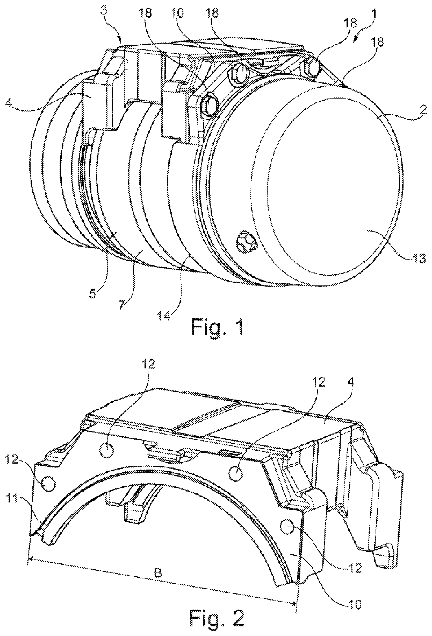
[0016] FIG. 1 shows an exemplary embodiment of a covering system according to the disclosure in perspective view,
[0017] FIG. 2 shows an exemplary embodiment of a bearing housing in perspective view,
[0018] FIG. 3 shows the cover of FIG. 1 in perspective front view,
[0019] FIG. 4 shows the cover of FIG. 1 in perspective rear view,
[0020] FIG. 5 shows the covering system of FIG. 1 in side view,
[0021] FIG. 6 shows a cutout feature of the connection between the cover and the bearing housing of the covering system of FIG. 1 in cross sectional view,
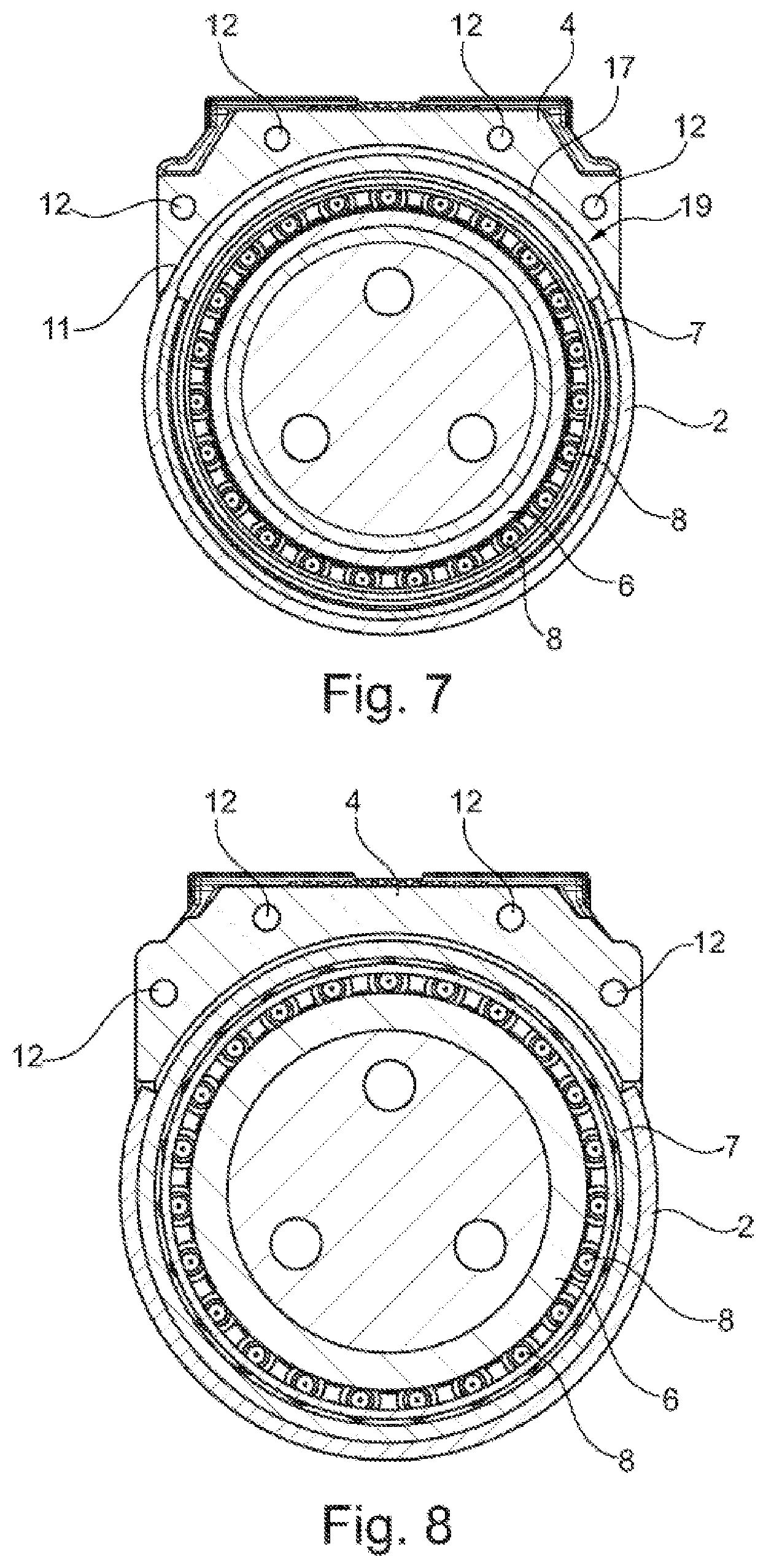
[0022] FIG. 7 shows the cross sectional view A-A of FIG. 5, and
[0023] FIG. 8 shows the cross sectional view B-B of FIG. 5.
[0024] In all of the figures, the same or equivalent parts are given the same reference symbols.
[0025] FIG. 1 and FIG. 5 to FIG. 8 represent an exemplary embodiment of a covering system 1 according to the disclosure for wheelset shafts of rail vehicles in various views. The covering system 1 includes a cover 2 and a wheelset bearing unit 3, the cover 2 being rotationally fixed to the wheelset bearing unit 3.
[0026] The wheelset bearing unit 3 includes a bearing housing 4, often also called an adapter, as well as a wheelset bearing 5. The wheelset bearing 5 includes a bearing inner race 6, a bearing outer race 7, a plurality of roller elements 8 arranged between the two bearing races 6, 7 and an end cap 9 rotationally fixed to the wheelset shaft, which axially closes off the wheelset bearing 5 starting from the axis of rotation of the wheelset bearing 5.
[0027] The end cap 9 of the wheelset bearing 5 is completely enclosed by the cover 2. That is, the cover 2 extends beyond the end cap 9 and partly surrounds the bearing outer race 7 of the wheelset bearing 5.
[0028] The bearing housing 4 is firmly connected to a bogie of a rail vehicle, not shown here, and represented in FIG. 2. At the end face 10 of the bearing housing 4 facing toward the cover 2 there is formed a circular arc shaped groove 11, which extends across the entire width B of the end face 10 of the bearing housing 4. The circular arc shape of the groove 11 in the bearing housing 4 is fashioned coaxially to the wheelset bearing 5.
[0029] Furthermore, four boreholes 12 are arranged on the end face 10 of the bearing housing 4, starting from the axis of rotation of the wheelset bearing 5, radially above the groove 11 in circular arc shape. The boreholes 12 are fashioned identically and arranged symmetrically to the radial midplane of the bearing housing 4.
[0030] The cover 2 is represented in various views in FIGS. 3 and 4.
[0031] The cover 2 is pot shaped and has a closed end face 13 and an open end face 14, the closed end face 13 facing away from the wheelset bearing unit 3. A recess 15 is present, extending from the open end face 14 in the axial direction, which extends in the circumferential direction across the width B of the bearing housing 4. Two flange segments 16 are formed flush at the recess 15. That is, the flange segments 16 are set off in the axial direction as compared to the open end face 14 of the cover 2. Hence, the flange segments 16 are formed between the two end faces 13, 14 of the cover 2, and the flange segments 16 lie directly against the recess 15. Each flange segment 16 has two boreholes 12, corresponding to the boreholes 12 at the end face 10 of the bearing housing 4.
[0032] On the flange segments 16 there is formed a circular arc shaped axial elevation 17, which extends along the entire circumference of the recess 15. That is, the elevation 17 protrudes into the recess 15 toward the wheelset bearing unit 3.
[0033] In the assembled state, as can be seen in FIG. 1 and FIG. 6, the flange segments 16 lie against the end face 10 of the bearing housing 4. The elevation 17 of the cover 2 protrudes into the groove 11 of the bearing housing 4. The depth T.sub.N of the groove 11 of the bearing housing 4, measured in the axial direction starting from the axis of rotation of the wheelset bearing 5, is larger than the depth T.sub.E of the elevation 17, so that the flange segments 16 lie directly against the end face 10 of the bearing housing 4.
[0034] Through the boreholes 12 of the flange segments 16, connection means 18, e.g. screws, protrude into the bearing housing 4, firmly connecting the cover 2 to the wheelset bearing unit 3, especially to the bearing housing 4.
[0035] The groove 11 in the bearing housing 4 and the elevation 17 on the cover 2 form a centering device 19 which serves for more easily orienting the cover 2 of the covering system 1 relative to the bearing housing 4 of the covering system 1 during the mounting process of the covering system 1, which simplifies the mounting of the cover 2.
[0036] In the cover 2 there is arranged a device, not depicted here, such as a generator unit. The cover 2 thus provides a covering of the device arranged therein and prevents the penetration of unwanted particles.
REFERENCE NUMERALS
[0037] 1 Covering system
[0038] 2 Cover
[0039] 3 Wheelset bearing unit
[0040] 4 Bearing housing
[0041] 5 Wheelset bearing
[0042] 6 Bearing inner race
[0043] 7 Bearing outer race
[0044] 8 Roller element
[0045] 9 End cap
[0046] 10 End face of bearing housing facing toward the cover
[0047] 11 Groove
[0048] 12 Borehole
[0049] 13 Closed end face of the cover
[0050] 14 Open end face of the cover
[0051] 15 Recess
[0052] 16 Flange segment
[0053] 17 Elevation
[0054] 18 Connection element
[0055] 19 Centering device
[0056] B Width of the end face of the bearing housing
[0057] T.sub.N Depth of the groove
[0058] T.sub.E Depth of the elevation
* * * * *
D00000
D00001
D00002
D00003
D00004
XML
uspto.report is an independent third-party trademark research tool that is not affiliated, endorsed, or sponsored by the United States Patent and Trademark Office (USPTO) or any other governmental organization. The information provided by uspto.report is based on publicly available data at the time of writing and is intended for informational purposes only.
While we strive to provide accurate and up-to-date information, we do not guarantee the accuracy, completeness, reliability, or suitability of the information displayed on this site. The use of this site is at your own risk. Any reliance you place on such information is therefore strictly at your own risk.
All official trademark data, including owner information, should be verified by visiting the official USPTO website at www.uspto.gov. This site is not intended to replace professional legal advice and should not be used as a substitute for consulting with a legal professional who is knowledgeable about trademark law.