Roll Stabilizer And Use Of A Roll Stabilizaer In A Motor Vehicle
KLANK; Michael ; et al.
U.S. patent application number 16/608250 was filed with the patent office on 2020-06-25 for roll stabilizer and use of a roll stabilizaer in a motor vehicle. The applicant listed for this patent is ZF Friedrichshafen AG. Invention is credited to Frank BERGER, Christoph ELBERS, Alexander HAEGELE, Michael KLANK.
| Application Number | 20200198434 16/608250 |
| Document ID | / |
| Family ID | 61911543 |
| Filed Date | 2020-06-25 |


| United States Patent Application | 20200198434 |
| Kind Code | A1 |
| KLANK; Michael ; et al. | June 25, 2020 |
ROLL STABILIZER AND USE OF A ROLL STABILIZAER IN A MOTOR VEHICLE
Abstract
A roll stabilizer for a motor vehicle having a housing (137, 237) with a first stabilizer element (110, 210) coupled to the housing and an electric motor (150, 250) located in the housing (137, 237). The transmission (160, 260) is coupled to the electric motor (150, 250) on a drive side, and the output side of the transmission (160, 260) is coupled to a second stabilizer element (115, 215) such that the stabilizer elements are electromechanically rotatable with respect to one another. The electric motor is designed as a Vernier motor.
| Inventors: | KLANK; Michael; (Osnabruck, DE) ; ELBERS; Christoph; (Stemwede, DE) ; HAEGELE; Alexander; (Alfhausen, DE) ; BERGER; Frank; (Lubbecke, DE) | ||||||||||
| Applicant: |
|
||||||||||
|---|---|---|---|---|---|---|---|---|---|---|---|
| Family ID: | 61911543 | ||||||||||
| Appl. No.: | 16/608250 | ||||||||||
| Filed: | March 27, 2018 | ||||||||||
| PCT Filed: | March 27, 2018 | ||||||||||
| PCT NO: | PCT/EP2018/057695 | ||||||||||
| 371 Date: | October 25, 2019 |
| Current U.S. Class: | 1/1 |
| Current CPC Class: | B60G 2204/4191 20130101; F16H 57/0006 20130101; H02K 7/116 20130101; B60G 2202/42 20130101; F16H 1/36 20130101; F16H 49/001 20130101; B60G 21/10 20130101; B60G 21/055 20130101; H02K 5/24 20130101; B60G 2206/427 20130101; B60G 21/0555 20130101 |
| International Class: | B60G 21/055 20060101 B60G021/055; H02K 5/24 20060101 H02K005/24; H02K 7/116 20060101 H02K007/116 |
Foreign Application Data
| Date | Code | Application Number |
|---|---|---|
| Apr 27, 2017 | DE | 10 2017 207 116.8 |
Claims
1-9. (canceled)
10. A roll stabilizer for a motor vehicle, the roll stabilizer comprising: an actuator (135, 235) having a housing (137, 237) with a first stabilizer element (110, 210) attached thereto and an electric motor (150, 250) located within the housing (137, 237), a transmission (160, 260) being connected with the electric motor (150, 250) on a drive side, the transmission (160, 260) being connected with a second stabilizer element (115, 215), on an output drive side, such that the first and the second stabilizer elements are electromechanically rotatable against one another, and the electric motor (250) is designed as a Vernier-motor.
11. The roll stabilizer according to claim 10, wherein the electric motor (250) has a longitudinal axis that is parallel to a longitudinal axis of the transmission (260), and the electric motor (250) and the transmission (260) have a common longitudinal axis.
12. The roll stabilizer according to claim 10, wherein the transmission (260) is positioned substantially within a rotor (252) of the electric motor.
13. The roll stabilizer according to claim 12, wherein the transmission (260) is a wave transmission and the rotor (252) of the electric motor (250) is coupled with an elliptic disc of the wave transmission.
14. The roll stabilizer according to claim 12, wherein the transmission (260) is one of a rotary gear transmission and a planetary transmission.
15. The roll stabilizer according to claim 124, wherein the transmission (260) is a planetary transmission, the electric motor (250) has a stator (255) arranged within and connected to the housing (237) in a rotationally fixed manner, a rotor (252) is positioned within and rotatable with respect to the stator (255), and the rotor is coupled to a first sun gear of the planetary transmission.
16. The roller stabilizer according to claim 14, wherein the planetary transmission is of an at least one planetary-stage design and has at least a spring for a noise reduction.
17. The roll stabilizer according to claim 16, wherein each of the at least one planetary-stage of the planetary transmission has two planet gears, and the two planet gears are structurally identical to one another and are preloaded against one another by the spring.
18. The roll stabilizer (205) according to claim 10, wherein the roll stabilizer is arranged in a chassis on at least one axle of the motor vehicle.
19. A roll stabilizer for a motor vehicle, the roll stabilizer comprising: an actuator having an housing with an input side and an output side, the input side of the housing being connected a first stabilizer element, and the output side of the housing being connected to the output side of the housing; an electric motor having a rotor and a stator, the electric motor being arranged radially within the housing such that the stator is connected to the housing in a fixed manner and the rotor is supported radially within the stator and is rotatable relative to the stator and the housing; a transmission being mounted radially within the rotor and being connected on a drive input side thereof with the electric motor, an output drive side of the transmission being connected with a second stabilizer element; the first and the second stabilizer elements being rotatable in opposite rotational directions; and the electric motor being designed as a Vernier-motor.
Description
[0001] This application is a National Stage completion of PCT/EP2018/057695 filed Mar. 27, 2018, which claims priority from German patent application serial no. 10 2017 207 116.8 filed Apr. 27, 2017.
FIELD OF THE INVENTION
[0002] The invention concerns a roll stabilizer and its application in a motor vehicle.
BACKGROUND OF THE INVENTION
[0003] Active roll stabilizers with a hydraulic or an electric motor actuator are known. In this case, a passive roll stabilizer is separated and an actuator comprising of a motor and a transmission is positioned between the stabilizer elements. The actuator can twist the two stabilizer elements against each other to minimize the rolling of the motor vehicle due to impulses of the roadway or during swerving or driving around curves. In this case, large actuating power is required so that, due to the limited assembly space, the motor and a transmission are positioned at the respective vehicle axle and axially next to each other.
[0004] An actuator is known through the EP 1 820 675 A1 for an active roll stabilizer whereby the actuator has an electric motor with a downstream three-stage planetary transmission which generates the output drive at the output side through its last planetary carrier. The electric motor and the planetary transmission are installed next to each other in a common enclosure of the actuator, whereby one side of the housing is connected in a rotationally fixed manner with its first stabilizer element. The second stabilizer element is connected in a rotationally fixed manner with the planetary carrier at the output side of the planetary transmission. During activation of the electric motor, the two stabilizer elements are twisted against each other to controllably counteract rolling movement of the vehicle's chassis.
SUMMARY OF THE INVENTION
[0005] Based on the above mentioned state of the technology, the object of the invention is improving an active roll stabilizer in terms of the available assembly space, as well as the optimization of the drive.
[0006] The invention includes the characteristics of the independent claims of the invention. Advantageous further embodiments result from the dependent claims.
[0007] In a first aspect, the invention concerns a roll stabilizer for a motor vehicle comprising an actuator with a housing, connected to the housing in a rotationally fixed manner is a first stabilizer element, and an electric motor installed and positioned in the housing. The transmission is connected on the drive side with an electric motor and on the output drive side with a second stabilizer element so that the stabilizer elements can be twisted against each other electro-mechanically. The invention is characterized by an electric motor which is designed as a Vernier motor and is connected, as a drive, to the transmission. A control unit captures the current driving situation and sends signals to electronics of the actuator, so that the motor rotates the transmission in one of the possible directions of rotation and thereby, depending on the drive situation, causes opposite rotation of the stabilizer elements. The inclination of the vehicle in a direction outside the curve can thus be changed or minimized, respectively. Also, the roll of the vehicle, due to an unevenness of the road, can be compensated for so that the impulse leads in the ideal case to no rolling movement of the vehicle. The passengers observe the lower inclination in curves as being more comfortable and the impulses, due to unevenness of the road, results in a driving experience similar to that on a flat road, because rolling is prevented or minimized.
[0008] The electric motor (E-Motor) is preferably designed as a brushless Vernier motor. This kind of E-Motor represents a highly efficient electric motor which, in comparison to conventional electric motors, has an improved volume efficiency. A Vernier motor can generate a high torque with less volume than a conventional E-Motor with a correspondingly larger volume. In other words, an E-motor can be made smaller and can at the same time generate at least the same or even higher power. In other words, the size can be reduced in comparison to the E-motor conventionally used in roll stabilizers, so that either the installation space for further components required within the actuator is available. Or rather, the size of the actuator can be reduced as a whole. Thus, a very compact roll stabilizer can be provided for each respective axle of the chassis so that the required assembly space, for instance for the steering, in particular the rear axle steering, or preferably an electric axle drive can be applied.
[0009] The Vernier motor is not only smaller than a comparable electric motor. It is also lower in weight and more power efficient than a comparable conventional E-Motor and has sufficient torque to effect rotation of the stabilizer elements against each other by means of the transmission. Through this construction, the size and therefore also the weight of the magnets can be reduced. Thus, less rare-earth needs to be used for the manufacture of the magnets which significantly reduces the cost of the Vernier motor as compared to a conventional E-Motor with the same power.
[0010] In a first embodiment, the Vernier motor is positioned with its longitudinal axis parallel to the longitudinal axis of the transmission. Hereby, the transmission is preferably positioned axially parallel to the longitudinal axis of the actuator housing so that also the longitudinal axis of the ends of the stabilizer elements is positioned axially parallel. Preferably, the longitudinal axes are positioned on top of each other which results in a common longitudinal axis. Contrary to the previously mentioned axis-parallel positioning, the coaxial construction can provide a more compact construction of the actuator and the roll stabilizer. This results in total, through the use of the Vernier motor, in an advantageous reduction in the assembly space.
[0011] In an additional preferred embodiment, the transmission is mainly, in particular completely, integrated within the E-Motor. In other words, the transmission is regarding its axial length substantially positioned within the rotor and/or stator. This results therefore in a compact drive unit, because the E-Motor and the transmission do not need to be positioned axially next to each other in the housing of the actuator. Therefore, the axial length of the actuator can clearly be reduced. Preferably, the axial length (width of the actuator) is reduced by half, and highly preferably by a third of the comparable actuator.
[0012] The transmission is designed in a preferred construction as in a wave transmission whereby the rotor of the Vernier motor is connected with the elliptic disc of the wave transmission. Wave transmissions have a low number of construction parts and can transfer large torques. Same applies with so-called voltage wave transmissions or harmonic drive transmissions, in English characterized as strain wave gear (SWG), it is a transmission with an elastic transmission element which is characterized by a high gear ratio and stiffness. It has mainly three components. Required is an elliptic steel disc with a shrunken roller bearing and a thin race (also called wave generator), whereby the elliptic disc causes the drive of the transmission. In addition, a deformable, cylindrical steel sleeve with outer gearing, the so-called flex-spline is required whereby the steel sleeve creates the output drive. Finally, a stiff cylindrical outer ring with inner gearing, the circular spline, is required. At the lower and the upper edge of the outer ring, its gear meshes with the Fiexspline. The outer gear ring of the steel sleeve has lesser teeth than the gearing of the outer ring. Preferably, that difference is two teeth. Flexspline and Circular spline have with each rotation a relative movement by two teeth, so that a rotational movement is created at a high gear ratio.
[0013] In an additional preferred embodiment, the transmission is designed as rotational impeller transmission, preferably a planetary transmission with at least one stage, or also as a Wolfram transmission. Rotational impeller transmissions can also transfer large torques and have for instance, in form of a planetary transmission, an advantageous quiet running. The Vernier motor drives the sun gear (in a multi-stage planetary transmission, the first sun gear) and the torque is transferred to the second stabilizer element via (with multi-stages, the last) the planetary carrier. It is rotatable relative to the housing and thus with respect to the first stabilizer element. The planetary carrier has at least three planetary gear which mesh with a ring gear which is positioned in the housing. Preferably, the ring gear is introduced into the housing so that the ring gear and the housing are designed as one-piece part.
[0014] Preferably, the Vernier motor has relative to the housing of the actuator a rotationally fixed stator, wherein inside of the stator is a rotatably mounted rotor connected with the transmission. In this type of electric motor, magnets are arranged on the outside of the stator, but they are much smaller in size than conventional electric motors. Thus, the required space of the Vernier electric motor is reduced overall. For this reason, in a preferred embodiment, the outer diameter of the actuator, without power loss, can be comparatively smaller and thus the space of the roll stabilizer can be reduced.
[0015] In a further preferred embodiment, at least one means, preferably a spring, for minimizing noise is provided in the at least one-stage planetary gear. The means may cause a bias of one or more of the gears or planetary carrier, so that it can not, especially when changing direction, come to a flank impact within the transmission. This is here important, because the operation noise of the actuator can be transferred through the stabilizer elements directly to the chassis and are audible by the passenger. For further acoustic decoupling of the actuator, one or more decoupling elements can be provided outside of the transmission, for instance between the transmission and the second stabilizer element. These decoupling elements can be integrated both inside the housing of the actuator or outside in the stabilizer elements themselves.
[0016] In another advantageous embodiment, the planetary transmission has, at least in each planetary stage, at least a two-part planetary gear whereby the two partial planetary gears are, preferably identical in construction and preloaded with a spring. In particular; the spring acts in the sense of a torsion spring so that flank impact is effectively avoided, since the partial planet gears are supported against the teeth of the ring gear. In addition, a preload in the axial direction can be provided so that movement and striking of the planetary gears in the axial direction can be avoided. The previously mentioned springs can be made of spring steel or an elastomer, or other suited elastic material, and can be designed in the form of a ring or in the form of disks.
[0017] In an additional aspect of the invention, an application of the roll stabilizer according to the invention is provided in a chassis of a motor vehicle is provided. The active roll stabilizer can be positioned on the front axle and/or on the rear axle. Due to the low energy consumption of the Vernier electric motor according to the invention, less energy is withdrawn from the electrical system of the motor vehicle for roll stabilization than when using an actuator with a conventional E-Motor, Beside the lower energy consumption during rotation, lower operating noise for the actuator occurs through the decoupling or preload, respectively. In addition, a weight reduction occurs in the sense of the economy of the vehicle with an active roll stabilizer.
[0018] The previously mentioned drive, by means of a Vernier motor, is also suitable for other applications, such as window lifters in vehicle doors, or similar actuating drives. Here, a compact, energy efficient and high-torque drive are required.
BRIEF DESCRIPTION OF THE DRAWINGS
[0019] The invention will be described below with reference to preferred embodiments with reference to the drawings. The drawings show:
[0020] FIG. 1 is a schematic view of a vehicle axis with an active roll stabilizer,
[0021] FIG. 2 is a detailed view of an embodiment of the roll stabilizer,
[0022] FIG. 3 is a detailed view of an embodiment of a roll stabilizer according to the invention.
DETAILED DESCRIPTION OF THE PREFERRED EMBODIMENTS
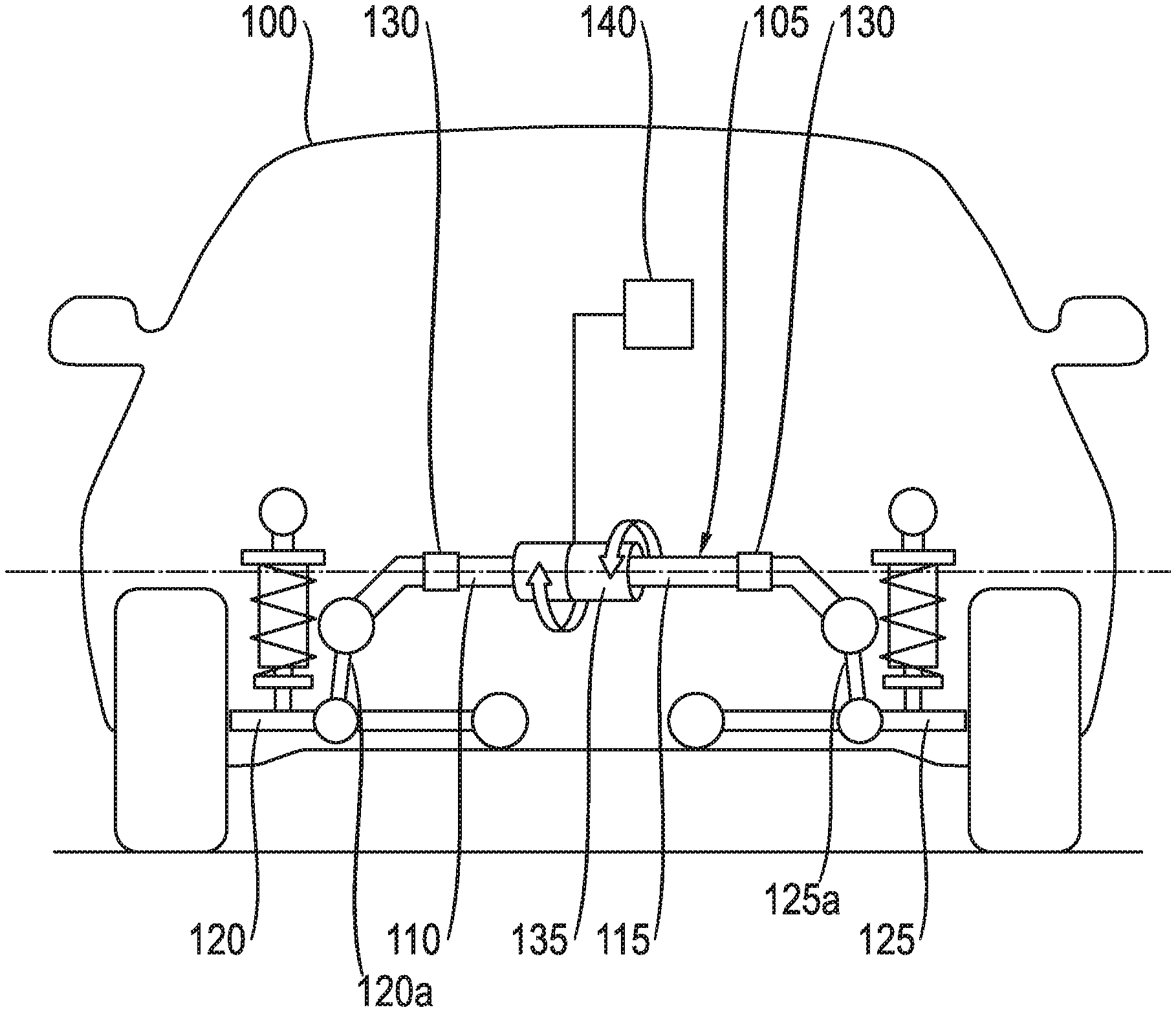
[0023] FIG. 1 shows a schematic representation of a vehicle 100 having a roll stabilizer 105 according to an embodiment of the present invention. The roll stabilizer 105 is realized as a two-part torsion rod with a first stabilizer element 110 and a second stabilizer element 115. Here, one end of the first stabilizer element 110 is connected with a first wheel suspension element 120 of the vehicle 100, and one end of the second stabilizer element 115 is connected with a second wheel suspension element 125 of the vehicle 100. The ends of the stabilizer elements 110, 115 are connected with pivotally mounted hinge supports 120a, 125a, which are connected with the chassis. The wheel suspension elements 120, 125 are, for instance, pivoted opposite and each assigned to a wheel control arm of the vehicle 100. The stabilizer elements 110, 115 are each installed by means of a chassis-solid construction bearing 130, pivotable around a common rotational axis D-D, at the chassis of the vehicle 100. The rotational axis D-D corresponds hereby in this example to a transverse axis of the vehicle 100. The stabilizer elements 100, 115, can be rotated against each other by means of an actuator 135 when the control unit 140 senses for instance an uneven road and this impulse is compensated for by a targeted rotational movement so that the chassis does not experience rolling movement, as it would be the case due to the copy effect of a passive roll stabilizer.
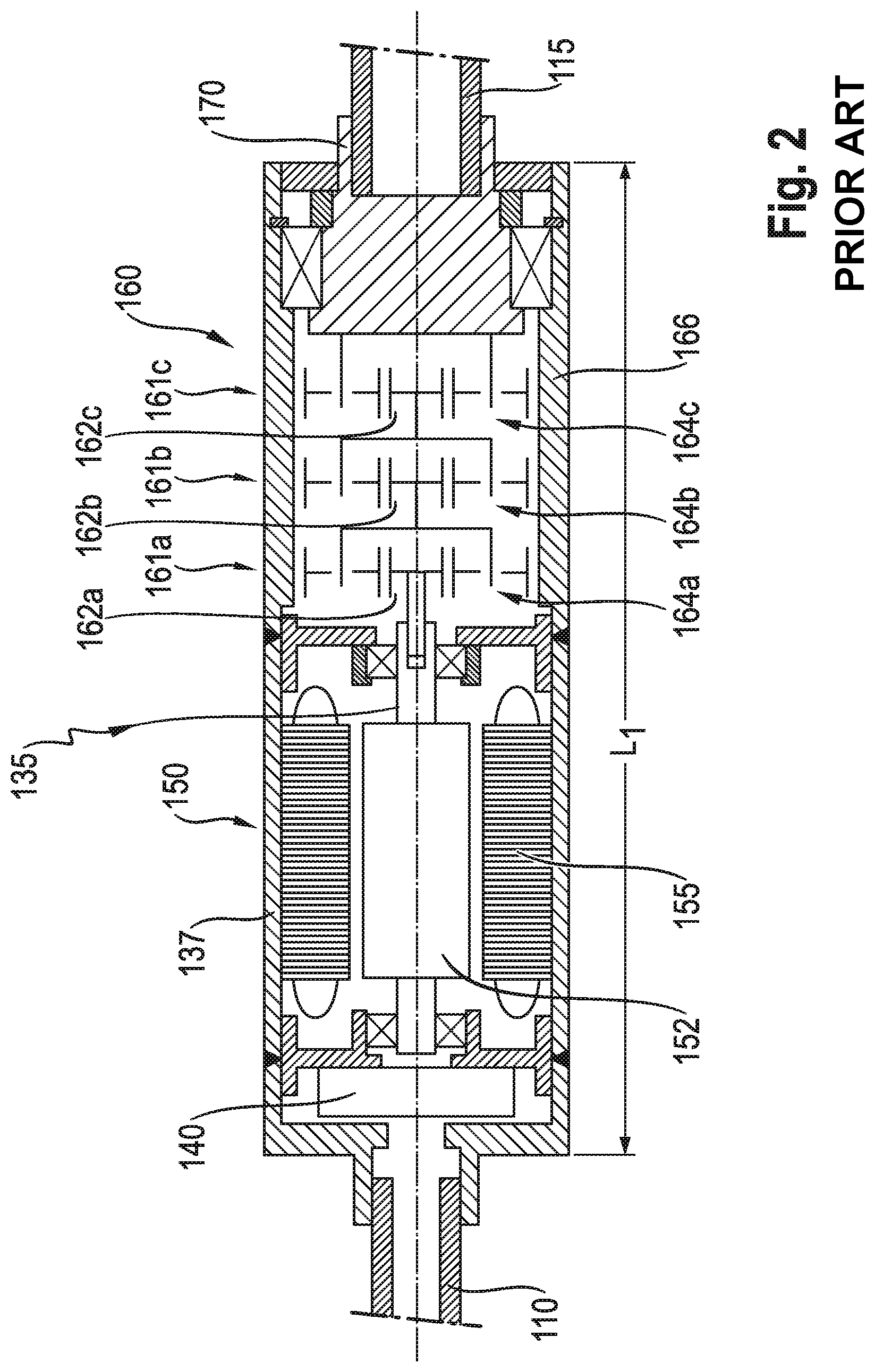
[0024] FIG. 2 shows the construction of an actuator 135 of a conventional active roll stabilizer 105 in accordance with the state of the technology. The roll stabilizer 105 has an actuator 135 with a housing 137. Positioned in the housing 137 is an E-Motor 150 with a housing-mounted stator 155, as well as a rotor 152 which is rotatably positioned in the housing 137. Further, a control unit or electronics 140, respectively for operating the actuator 135 is housed in the housing 137 in the direction of the E-Motor end. Axially next to the E-Motor, a transmission 160 is positioned in the form of a planetary transmission. The E-Motor 150 is operationally connected with the first sun gear 162a of the first planetary stage 161a. The planetary transmission has a total of three planetary stages 161a, 161b, 161c with three planetary carriers 164a, 164b, 164c. The planetary gears of the respective planetary carriers 164a, 164b, 164c mesh with a ring gear 166 which is positioned on the inner side of the housing. A first stabilizer element 110 is integrally connected to the E-Motor end of the actuator 135. The second stabilizer element 115 is operationally connected with the last planetary carrier 164c. The torque of the E-Motor 150 is transmitted via the transmission 160 to the stabilizer element 115, so that there is rotation of the stabilizer element 115 relative to the housing 137 and ultimately with respect to the stabilizer element 110. The housing has an axial extent L1, which results from the arrangement of the E-Motor 150 next to the transmission 160. It can clearly be seen that the E-Motor 150 and the transmission 160 each occupy about one half of the width of the actuators as installation space of the actuator.
[0025] FIG. 3 shows an embodiment according to the invention, in which a much more compact construction of the actuator can clearly be seen. The planetary transmission 260 is designed analogously to the transmission in FIG. 2 and is disposed here within the E-Motor 250. Within the housing 237, the control unit or electronics 240, respectively, of the actuator 235 is accommodated analogously to the arrangement according to FIG. 2. In other words, the transmission does not axially extend substantially beyond the Vernier motor. The ring gear 256 is positioned inside of the rotor 252 and supported on the housing 235 via a support member 267. Through the coaxial positioning of the E-Motor 250 and the transmission 260, considerable assembly space can be saved. The width of the actuator 235 can be reduced to L.sub.2 by approximately 2/3 to 1/2 the width L.sub.1 of the actuator 135 of FIG. 2 (in accordance with the state of the technology). This is especially possible because the Vernier motor, in this case with a hollow rotor, takes up less space and can accommodate the transmission in its interior. It is obvious, in accordance with FIG. 2, that in a conventional E-Motor a transmission cannot be integrated in the E-Motor.
[0026] In addition to the gear arrangement shown in FIG. 3, further transmissions are conceivable that can be arranged within the electric motor or the Vernier motors.
REFERENCE CHARACTERS
[0027] 100 Vehicle [0028] 105, 205 Roll Stabilizer [0029] 110, 210 first Stabilizer Element [0030] 115, 215 second Stabilizer Element [0031] 120 first Wheel Suspension Element [0032] 120a first Hinged Support [0033] 125 second Wheel Suspension Element [0034] 125a second Hinged Support [0035] 130 Structure Bearing [0036] 135, 235 Actuator [0037] 137, 237 Housing [0038] 140, 240 Control Unit, Electronics [0039] 150, 250 Electric Motor [0040] 152, 252 Rotor [0041] 155, 255 Stator [0042] 160, 260 Transmission [0043] 161a b,c Planetary Stage [0044] 162a,b,c Sun Gear [0045] 164a,b,c Planetary Carrier [0046] 166, 266 Ring Gear [0047] 170, 270 Output Drive
* * * * *
D00000
D00001
D00002
D00003
XML
uspto.report is an independent third-party trademark research tool that is not affiliated, endorsed, or sponsored by the United States Patent and Trademark Office (USPTO) or any other governmental organization. The information provided by uspto.report is based on publicly available data at the time of writing and is intended for informational purposes only.
While we strive to provide accurate and up-to-date information, we do not guarantee the accuracy, completeness, reliability, or suitability of the information displayed on this site. The use of this site is at your own risk. Any reliance you place on such information is therefore strictly at your own risk.
All official trademark data, including owner information, should be verified by visiting the official USPTO website at www.uspto.gov. This site is not intended to replace professional legal advice and should not be used as a substitute for consulting with a legal professional who is knowledgeable about trademark law.