In Situ Optical Feedback
CALDWELL; Scott ; et al.
U.S. patent application number 16/613262 was filed with the patent office on 2020-06-25 for in situ optical feedback. This patent application is currently assigned to Branson Ultrasonics Corporation. The applicant listed for this patent is Branson Ultrasonics Corporation. Invention is credited to Scott CALDWELL, Raul PASOLS, Sean TRIMBY.
| Application Number | 20200198254 16/613262 |
| Document ID | / |
| Family ID | 64395878 |
| Filed Date | 2020-06-25 |


| United States Patent Application | 20200198254 |
| Kind Code | A1 |
| CALDWELL; Scott ; et al. | June 25, 2020 |
In Situ Optical Feedback
Abstract
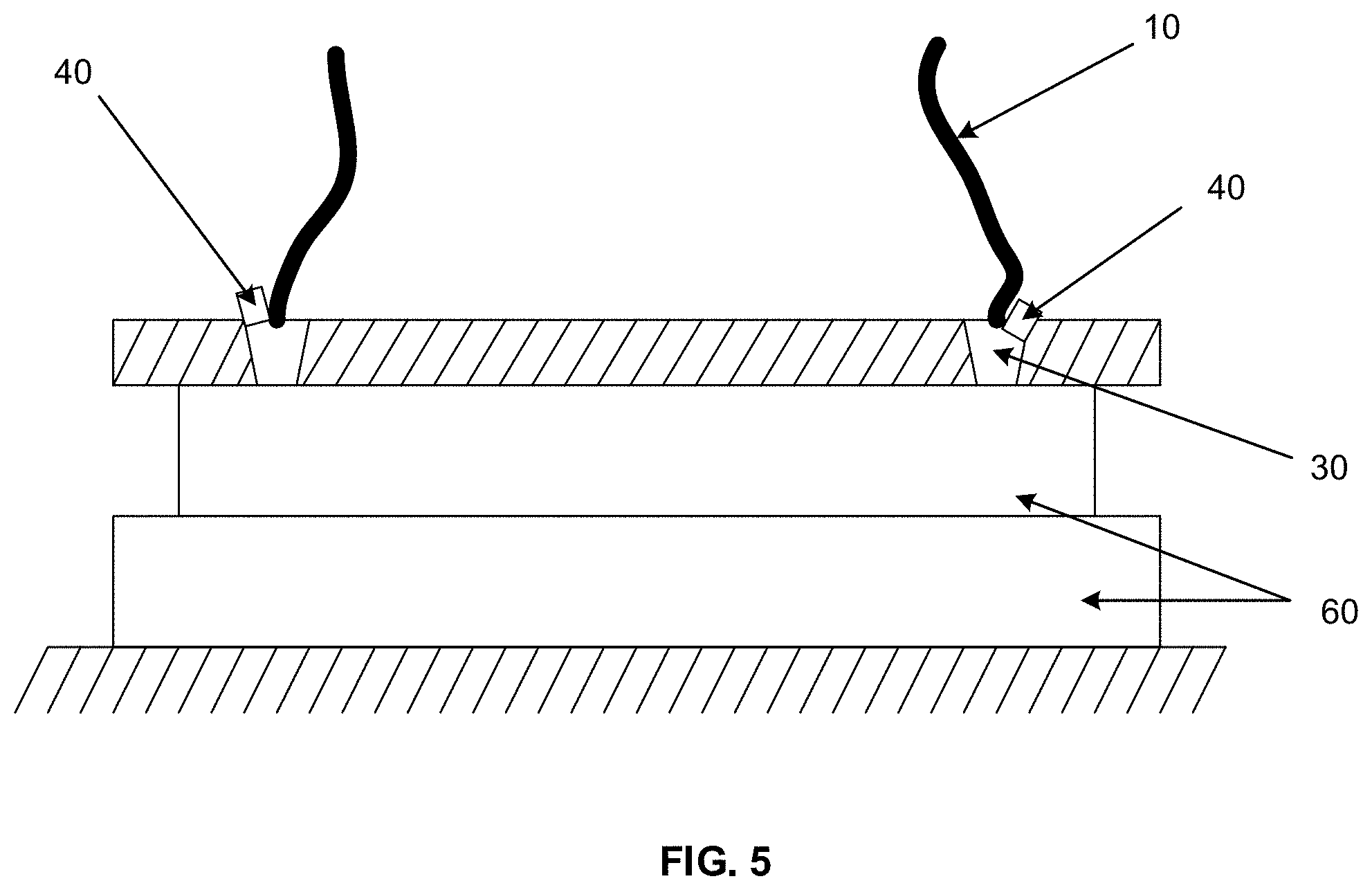
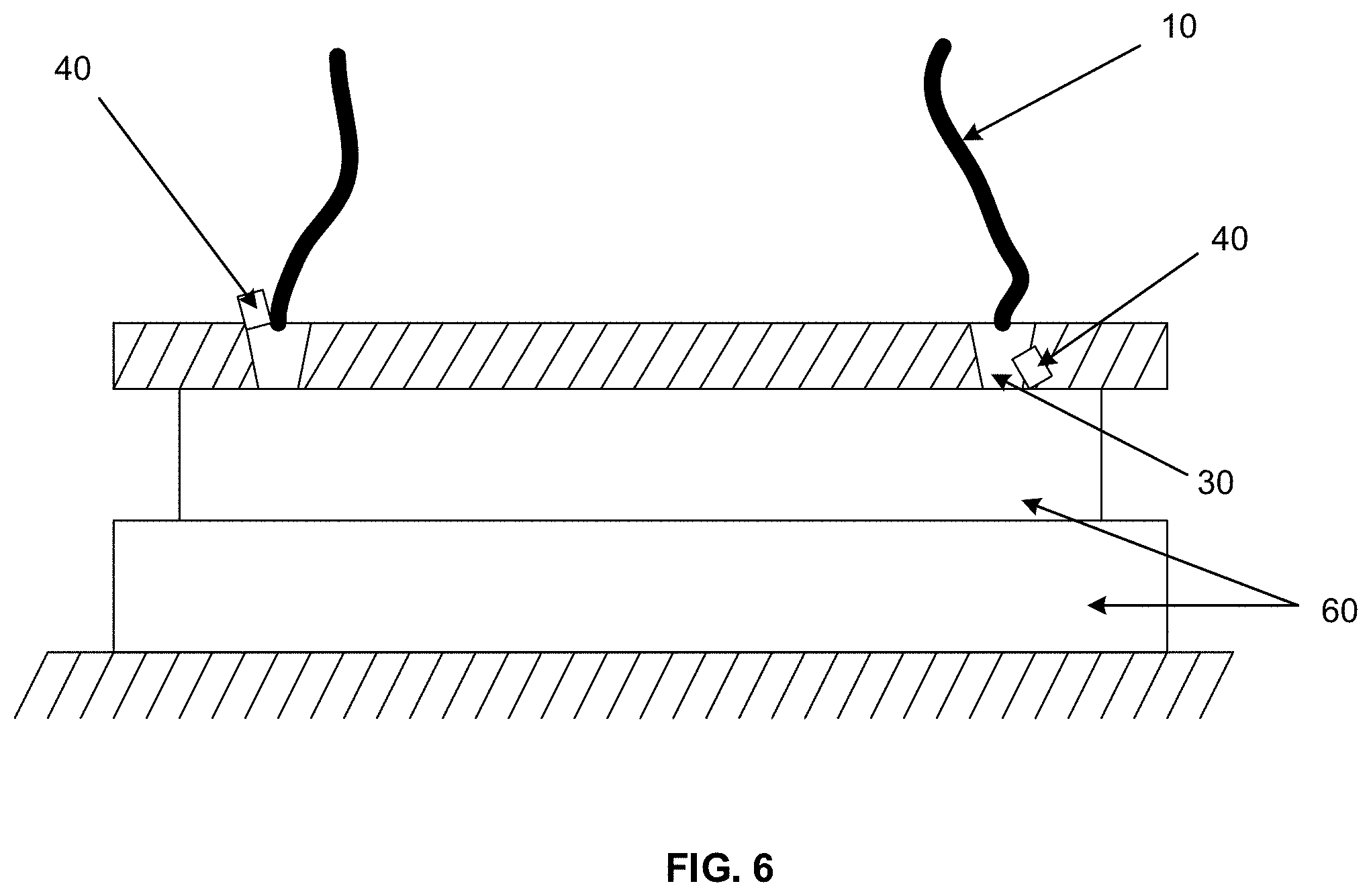
Sensors incorporated within a waveguide detect a laser light output from at least a laser delivery optical fiber to provide in situ feedback of the laser light intensity detected by the sensor. The sensors may detect laser light directly from the laser delivery optical fiber or as reflected back from a plurality of work pieces during a weld cycle. In various aspects, the feedback provided from the sensors is used to control the laser light intensity or to alert an operator that the laser light intensity is below a predetermined parameter.
| Inventors: | CALDWELL; Scott; (New Milford, CT) ; TRIMBY; Sean; (Geneseo, NY) ; PASOLS; Raul; (Rochester, NY) | ||||||||||
| Applicant: |
|
||||||||||
|---|---|---|---|---|---|---|---|---|---|---|---|
| Assignee: | Branson Ultrasonics
Corporation Danbury CT |
||||||||||
| Family ID: | 64395878 | ||||||||||
| Appl. No.: | 16/613262 | ||||||||||
| Filed: | May 23, 2018 | ||||||||||
| PCT Filed: | May 23, 2018 | ||||||||||
| PCT NO: | PCT/US18/34187 | ||||||||||
| 371 Date: | November 13, 2019 |
Related U.S. Patent Documents
| Application Number | Filing Date | Patent Number | ||
|---|---|---|---|---|
| 62511403 | May 26, 2017 | |||
| Current U.S. Class: | 1/1 |
| Current CPC Class: | B23K 26/324 20130101; B29C 65/1635 20130101; B29C 66/73921 20130101; B29C 65/1687 20130101; B23K 26/707 20151001; B23K 26/70 20151001; B29C 65/1696 20130101; B29C 66/41 20130101; B29C 65/1667 20130101; B29C 66/95 20130101; B23K 26/32 20130101; B29C 65/167 20130101; B29C 66/1122 20130101; B29C 65/1612 20130101; B29C 66/242 20130101; B23K 2103/42 20180801 |
| International Class: | B29C 65/16 20060101 B29C065/16; B29C 65/00 20060101 B29C065/00; B23K 26/70 20060101 B23K026/70 |
Claims
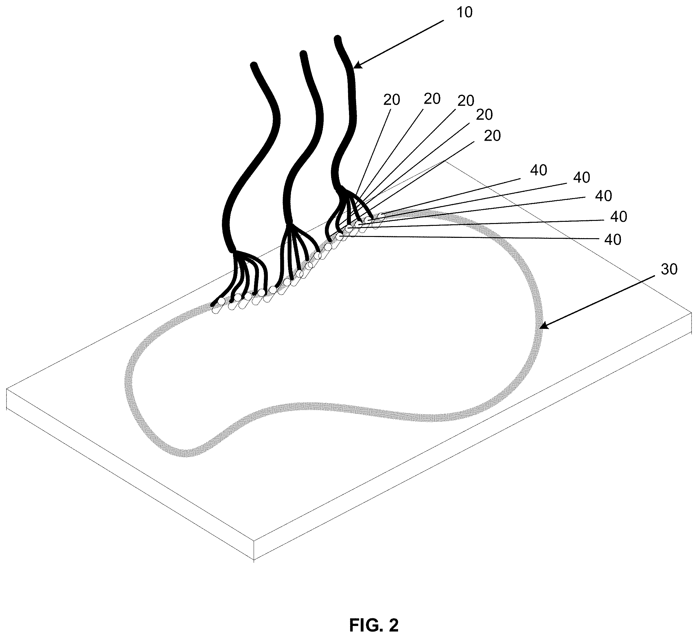
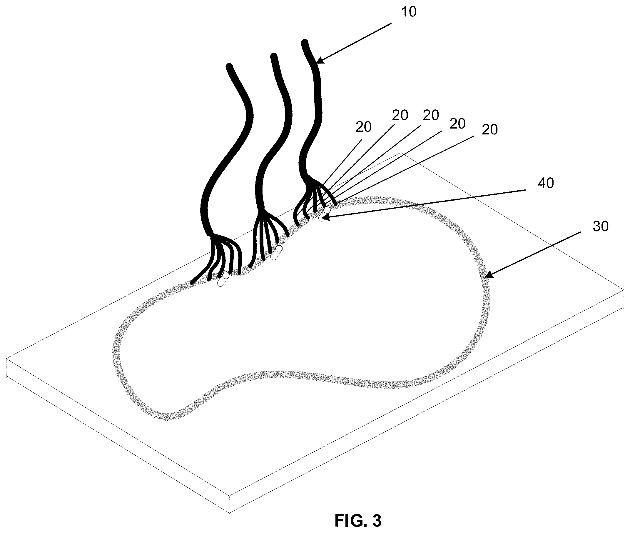
1. A method for sensing the output of laser light intensity used to weld a plurality of work pieces in a simultaneous laser welding system, the method comprising: directing a laser source from a laser bank through a plurality of laser delivery bundles, wherein each of the plurality of laser delivery bundles are comprised of at least a laser delivery optical fiber, wherein the plurality of laser delivery bundles deliver laser light through the at least the laser delivery optical fiber through a waveguide to the plurality of work pieces to be welded; and incorporating a plurality of sensors within the waveguide, wherein each sensor senses a laser light output by one of the plurality of the laser delivery bundles.
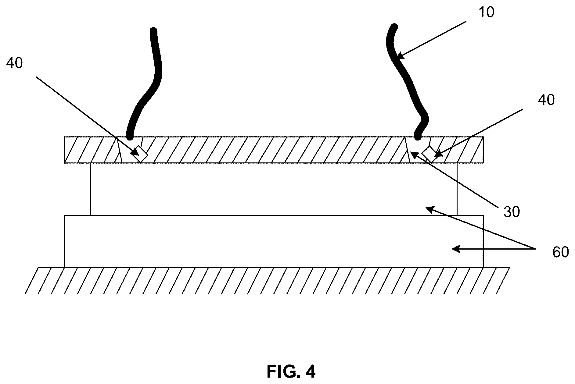
2. The method according to claim 1, wherein the incorporating a plurality of sensors within the waveguide comprises incorporating at least a sensor positioned within the waveguide to sense laser light directed from a delivery end of at least an associated laser delivery optical fiber.
3. The method according to claim 1, wherein the incorporating a plurality of sensors within the waveguide comprises incorporating at least a sensor positioned within the waveguide to sense laser light in a direction substantially parallel to the direction in which laser light is delivered at the delivery end of the laser delivery optical fiber.
4. The method according to claim 1, wherein the plurality of sensors relays the sensed laser light output to a controller.
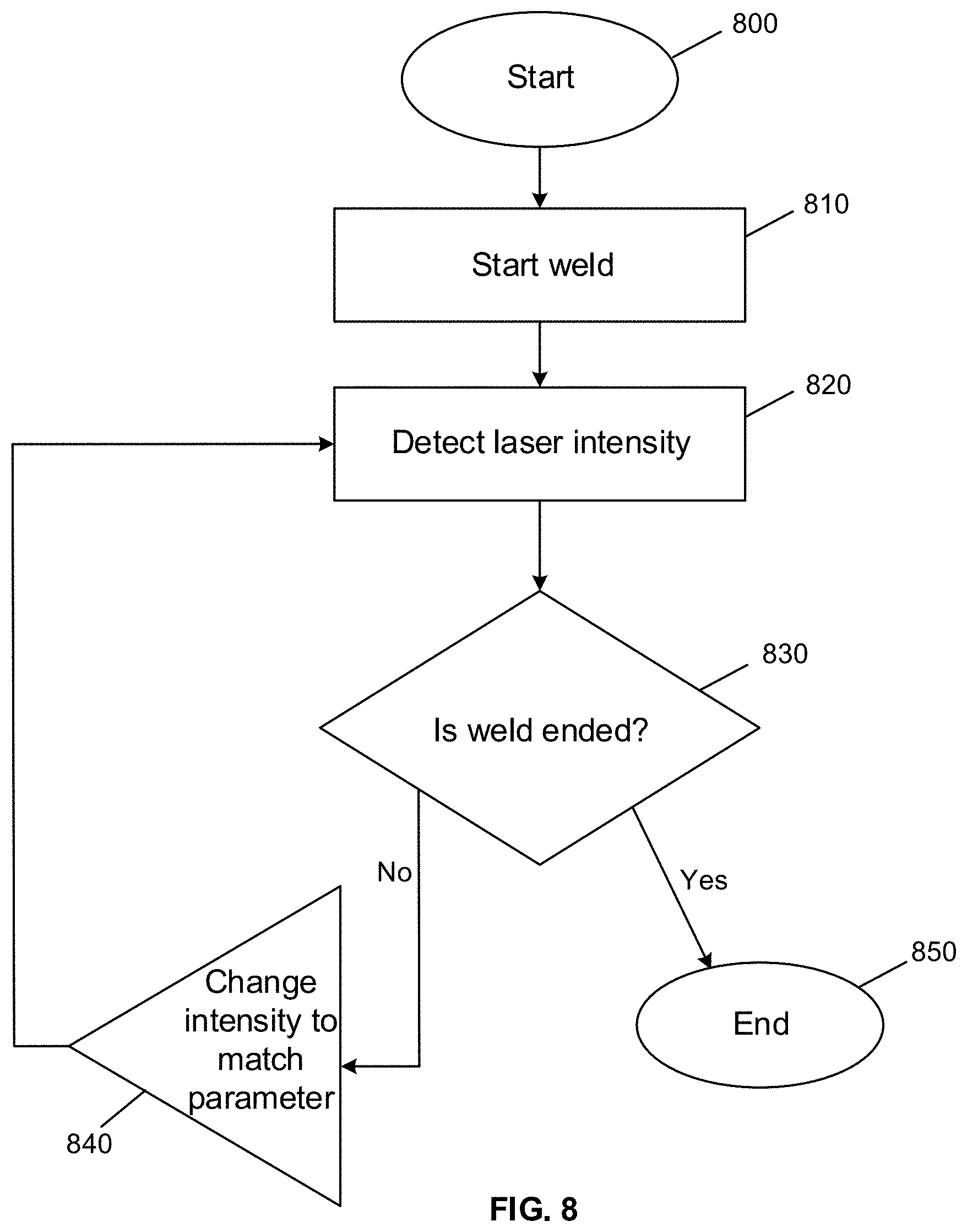
5. The method according to claim 4, further comprising alerting a user via the controller when a sensor senses that a laser light output by one of the plurality of the laser delivery bundles is below a predetermined parameter.
6. The method according to claim 4, further comprising adjusting the laser light intensity of a laser delivery bundle via the controller when a sensor senses that a laser light output by one of said laser delivery bundle is unsatisfactory.
7. The method according to claim 1, wherein the directing a laser source from a laser bank through a plurality of laser delivery bundles further comprises delivering laser light through a plurality of legs.
8. A laser welding apparatus, the laser welding apparatus comprising: a laser bank for outputting from a laser source laser light through a plurality of laser delivery bundles through a wave guide to a plurality of work pieces to be welded, wherein each said laser delivery bundle is comprised of at least a laser delivery optical fiber; and at least a sensor incorporated within said wave guide for sensing said laser light output by one of said plurality of laser delivery bundles, wherein said at least a sensor relays the sensed laser light output to a controller.
9. The laser welding apparatus of claim 8, wherein the at least a sensor is positioned within the waveguide to face a delivery end of at least an associated laser delivery optical fiber.
10. The laser welding apparatus of claim 8, wherein the at least a sensor is positioned within the waveguide in a direction substantially parallel to the direction in which laser light is delivered at a delivery end of the laser delivery optical fiber.
11. The laser welding apparatus of claim 8, wherein the controller is configured to alert a user that a laser light output by one of said laser delivery bundles is below a predetermined parameter.
12. The laser welding apparatus of claim 8, wherein the controller is configured to adjust the laser light output by one of said laser delivery bundles when the laser light output by one of said laser delivery bundles is unsatisfactory.
13. The laser welding apparatus of claim 8, wherein at least a laser delivery bundle is comprised of a plurality of legs.
Description
CROSS-REFERENCE TO RELATED APPLICATIONS
[0001] This application claims the benefit of U.S. Provisional Application No. 62/511,403 filed on May 26, 2017. The entire disclosure of the above application is incorporated herein by reference.
FIELD
[0002] The present disclosure relates to plastics welding and, more particularly, relates to assessing optical fibers in direct delivery welding and simultaneous laser welding applications.
BACKGROUND
[0003] This section provides background information related to the present disclosure which is not necessarily prior art.
[0004] Laser welding is commonly used to join plastic or resinous parts, such as thermoplastic parts, at a welding zone.
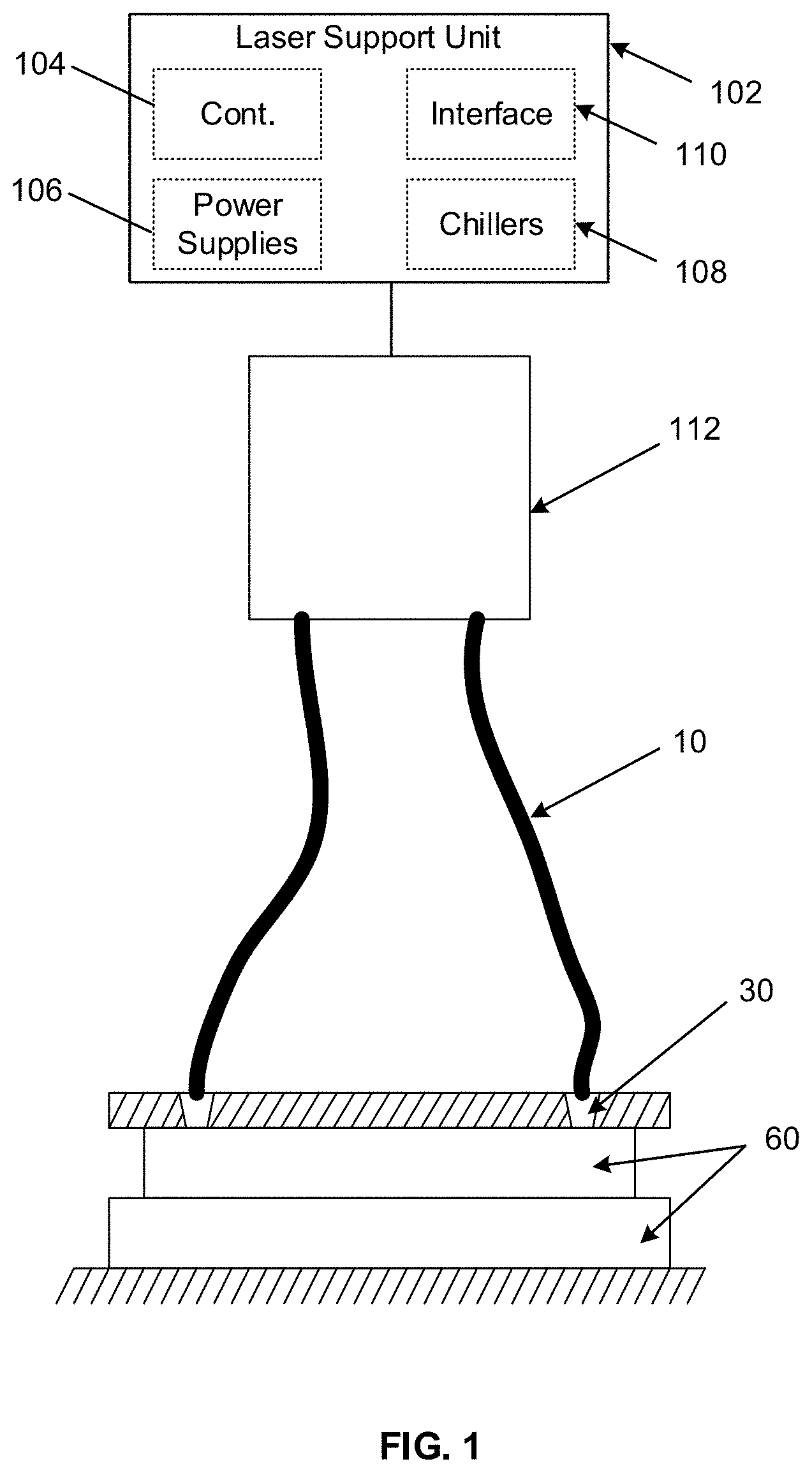
[0005] There are many different laser welding technologies. One useful technology is simultaneous through transmissive infrared welding, referred to herein as STTIr. In STTIr, the full weld path or area (referred to herein as the weld path) is simultaneously exposed to laser radiation, such as through a coordinated alignment of a plurality of laser light sources, such as laser diodes. An example of STTIr is described in U.S. Pat. No. 6,528,755 for "Laser Light Guide for Laser Welding," the entire disclosure of which is incorporated herein by reference. In STTIr, the laser radiation is typically transmitted from one or more laser sources to the parts being welded through one or more optical waveguides which conform to the contours of the parts' surfaces being joined along the weld path. To ensure an accurate and comprehensive weld, the gap between any waveguide and the workpiece closest to the waveguide is kept as small as possible. Correspondingly, to improve efficiency, the gap between the delivery end of the fiber bundle and the waveguide is also kept as small as possible.
SUMMARY
[0006] This section provides a general summary of the disclosure, and is not a comprehensive disclosure of its full scope or all of its features.
[0007] The present technology provides a method for sensing the output of laser light intensity used to weld a plurality of work pieces in a simultaneous laser welding system. The method includes directing a laser source from a laser bank through a plurality of laser delivery bundles, wherein each of the plurality of laser delivery bundles are comprised of at least a laser delivery optical fiber. The plurality of laser delivery bundles deliver laser light through the at least the laser delivery optical fiber through a waveguide to the plurality of work pieces to be welded. A plurality of sensors is incorporated within the waveguide, and each sensor senses a laser light output by one of the plurality of the laser delivery bundles. In other embodiments, incorporating the plurality of sensors within the waveguide comprises incorporating at least a sensor positioned within the waveguide to sense laser light directed from a delivery end of at least an associated laser delivery optical fiber. In yet other embodiments, the incorporating a plurality of sensors within the waveguide comprises incorporating at least a sensor positioned within the waveguide to sense laser light in a direction substantially parallel to the direction in which laser light is delivered at the delivery end of the laser delivery optical fiber. In further embodiments, the plurality of sensors relays the sensed laser light output to a controller. In other such further embodiments, a user is alerted via the controller when a sensor senses that a laser light output by one of the plurality of the laser delivery bundles is below a predetermined parameter. In yet other such further embodiments, the laser light intensity of the laser delivery bundle is adjusted via the controller when a sensor senses that a laser light output by one of the laser delivery bundles is unsatisfactory. In even further embodiments, directing the laser source from a laser bank through a plurality of laser delivery bundles further comprises delivering laser light through a plurality of legs.
[0008] The present technology also provides a laser welding apparatus. The laser welding apparatus comprises a laser bank for outputting from a laser source laser light through a plurality of laser delivery bundles through a wave guide to a plurality of work pieces to be welded. Each laser delivery bundle comprises at least a laser delivery optical fiber. At least a sensor is incorporated within the wave guide for sensing the laser light output by one of said plurality of laser delivery bundles, and the at least a sensor relays the sensed laser light output to a controller. In other embodiments, the at least a sensor is positioned within the waveguide to face the delivery end of at least an associated laser delivery optical fiber. In yet other embodiments, the at least a sensor is positioned within the waveguide in a direction substantially par
D00000
D00001
D00002
D00003
D00004
D00005
D00006
D00007
D00008
XML
uspto.report is an independent third-party trademark research tool that is not affiliated, endorsed, or sponsored by the United States Patent and Trademark Office (USPTO) or any other governmental organization. The information provided by uspto.report is based on publicly available data at the time of writing and is intended for informational purposes only.
While we strive to provide accurate and up-to-date information, we do not guarantee the accuracy, completeness, reliability, or suitability of the information displayed on this site. The use of this site is at your own risk. Any reliance you place on such information is therefore strictly at your own risk.
All official trademark data, including owner information, should be verified by visiting the official USPTO website at www.uspto.gov. This site is not intended to replace professional legal advice and should not be used as a substitute for consulting with a legal professional who is knowledgeable about trademark law.