Device for Degassing and/or Dehydrating a Hydraulic Oil, and Hydraulic Unit having a Tank and having such a Device
Reusch; Bastian ; et al.
U.S. patent application number 16/716600 was filed with the patent office on 2020-06-25 for device for degassing and/or dehydrating a hydraulic oil, and hydraulic unit having a tank and having such a device. The applicant listed for this patent is Robert Bosch GmbH. Invention is credited to Ralf Maier, Hermann Mehling, Bastian Reusch.
| Application Number | 20200197837 16/716600 |
| Document ID | / |
| Family ID | 70969832 |
| Filed Date | 2020-06-25 |


| United States Patent Application | 20200197837 |
| Kind Code | A1 |
| Reusch; Bastian ; et al. | June 25, 2020 |
Device for Degassing and/or Dehydrating a Hydraulic Oil, and Hydraulic Unit having a Tank and having such a Device
Abstract
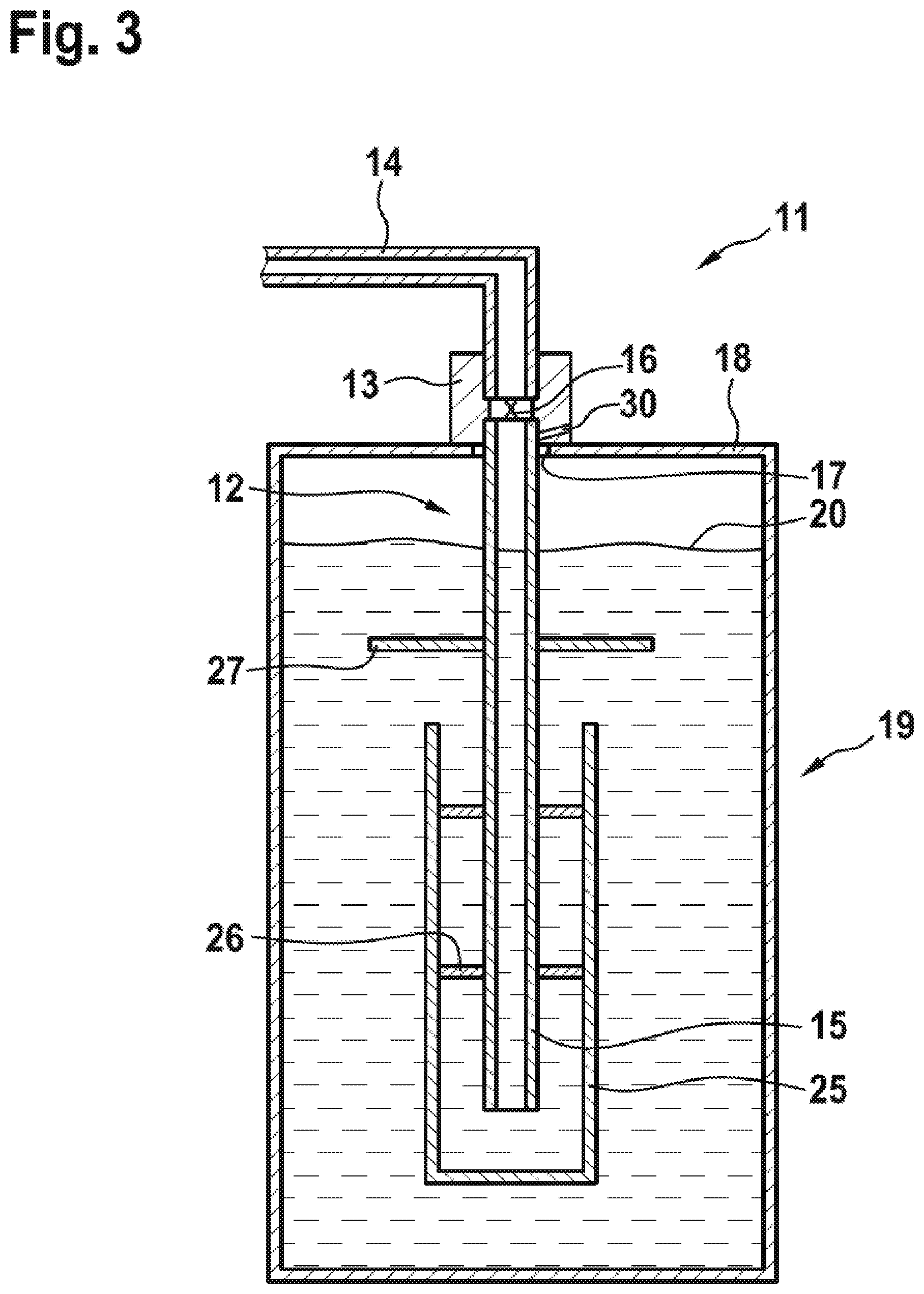
A device for degassing and/or dehydrating a hydraulic oil includes a flow lance, a flow duct, and a decoupling module. The flow lance includes a restriction site via which the hydraulic oil flows under a high pressure drop. The flow duct is configured as a pipe that is located downstream of the restriction site. The quantity of oil that flows via the restriction site and a throughflow cross section of the restriction site are coordinated to one another such that a cavitation zone or supercavitation zone forms downstream of the restriction site. The flow duct has a significantly larger cross section with respect to the throughflow cross section of the restriction site. For a quiet operation of the device, the flow lance is held in the decoupling module via which the flow lance is configured to be fastened in a vibration-decoupled manner to a tank.
| Inventors: | Reusch; Bastian; (Gemuenden, DE) ; Mehling; Hermann; (Karlstadt-Stetten, DE) ; Maier; Ralf; (Neuendorf, DE) | ||||||||||
| Applicant: |
|
||||||||||
|---|---|---|---|---|---|---|---|---|---|---|---|
| Family ID: | 70969832 | ||||||||||
| Appl. No.: | 16/716600 | ||||||||||
| Filed: | December 17, 2019 |
| Current U.S. Class: | 1/1 |
| Current CPC Class: | B01D 19/0036 20130101; B01D 19/0063 20130101; B01D 19/0005 20130101; B01D 19/0078 20130101 |
| International Class: | B01D 19/00 20060101 B01D019/00 |
Foreign Application Data
| Date | Code | Application Number |
|---|---|---|
| Dec 20, 2018 | DE | 10 2018 222 418.8 |
Claims
1. A device for degassing and/or dehydrating a hydraulic oil, comprising: a flow lance that includes a restriction site via which the hydraulic oil flows under a high pressure drop; and a flow duct configured as a pipe that is located downstream of the restriction site, wherein a quantity of the hydraulic oil that flows via the restriction site and a throughflow cross section of the restriction site are coordinated to one another such that a cavitation zone or supercavitation zone forms downstream of the restriction site, wherein the flow duct has a significantly larger cross section with respect to the throughflow cross section of the restriction site, and wherein the flow lance is held in a decoupling module via which the flow lance is configured to be fastened in a vibration-decoupled manner to a tank.
2. The device according to claim 1, wherein the flow lance is radially surrounded in sections by the decoupling module.
3. The device according to claim 1, wherein the flow lance is axially braced on the decoupling module.
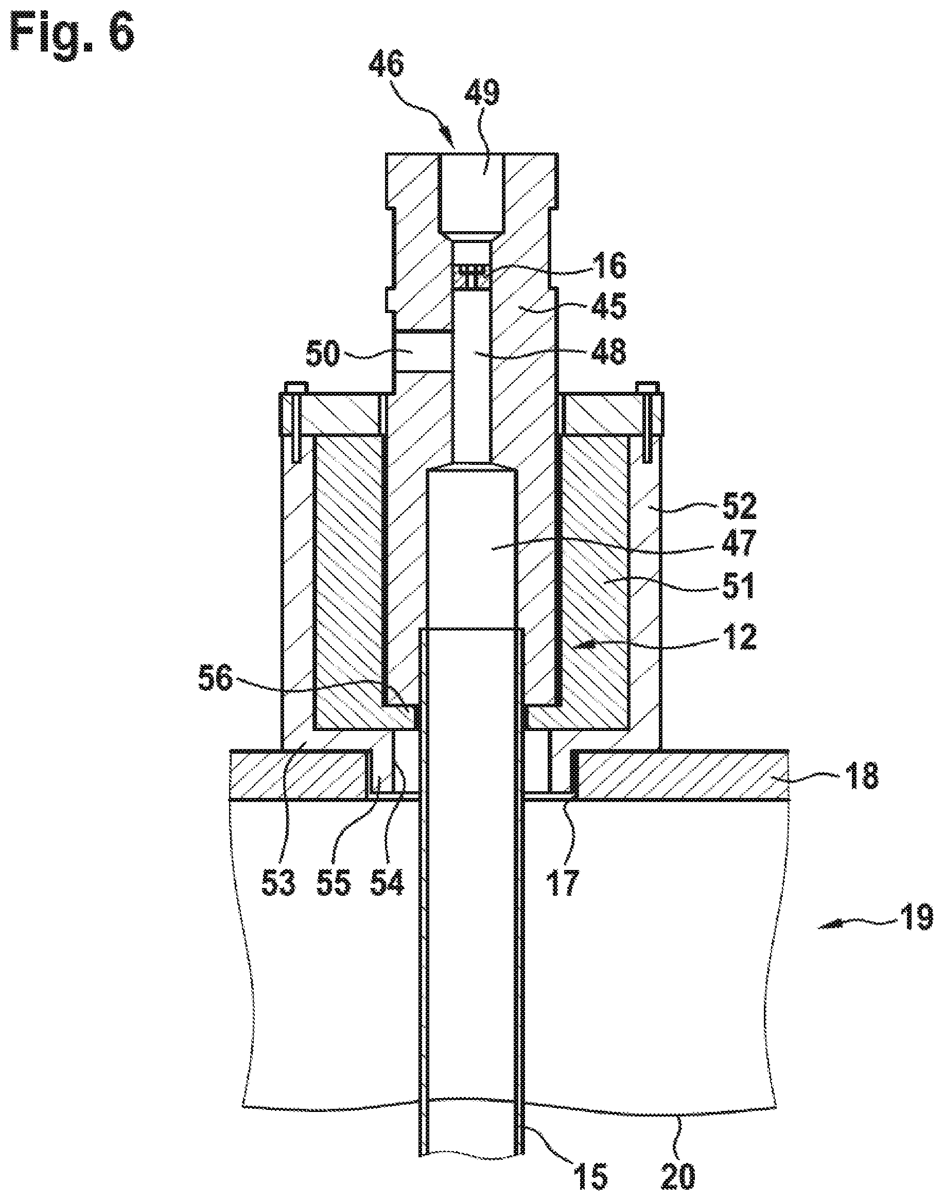
4. The device according to claim 2, wherein the decoupling module is configured as a buffer having a passage that receives the flow lance.
5. The device according to claim 4, wherein the buffer includes an inner band on which the flow lance is configured to be axially placed.
6. The device according to claim 4, wherein the buffer includes passages configured to receive fastening screws.
7. The device according to claim 4, wherein the buffer is axially compressed.
8. The device according to claim 4, wherein the buffer is surrounded by a housing configured to be fastened to the tank.
9. The device according to claim 8, wherein the housing includes a hollow spigot that surrounds the flow lance, the housing configured to be inserted into an opening of the tank via the hollow spigot.
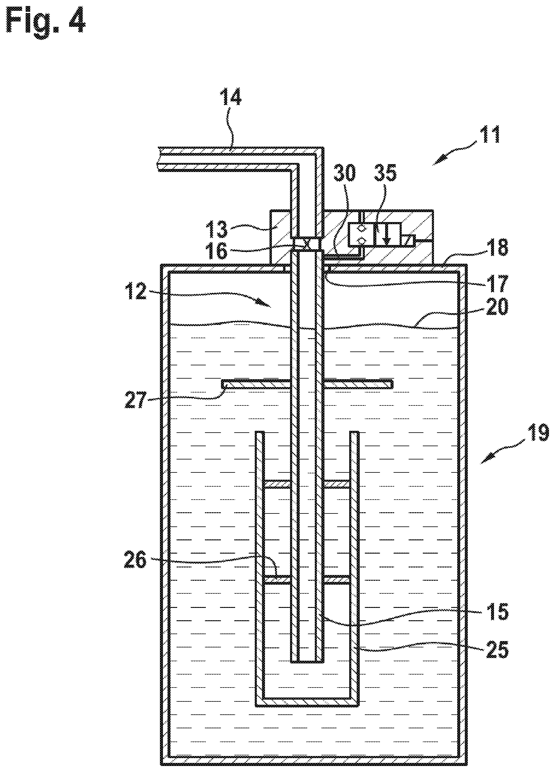
10. The device according to claim 1, wherein at least one valve is arranged on the decoupling module.
11. The device according to claim 1, wherein the flow duct terminates in a casing that (i) is closed on a closed end of the casing that is located below the flow duct, (ii) surrounds the flow duct on at least one part of a length of the casing, and (iii) is open on an open end of the casing that is located within a length of the flow duct.
12. The device according to claim 11, wherein a diverting metal sheet is arranged in a gap above the open end of the casing.
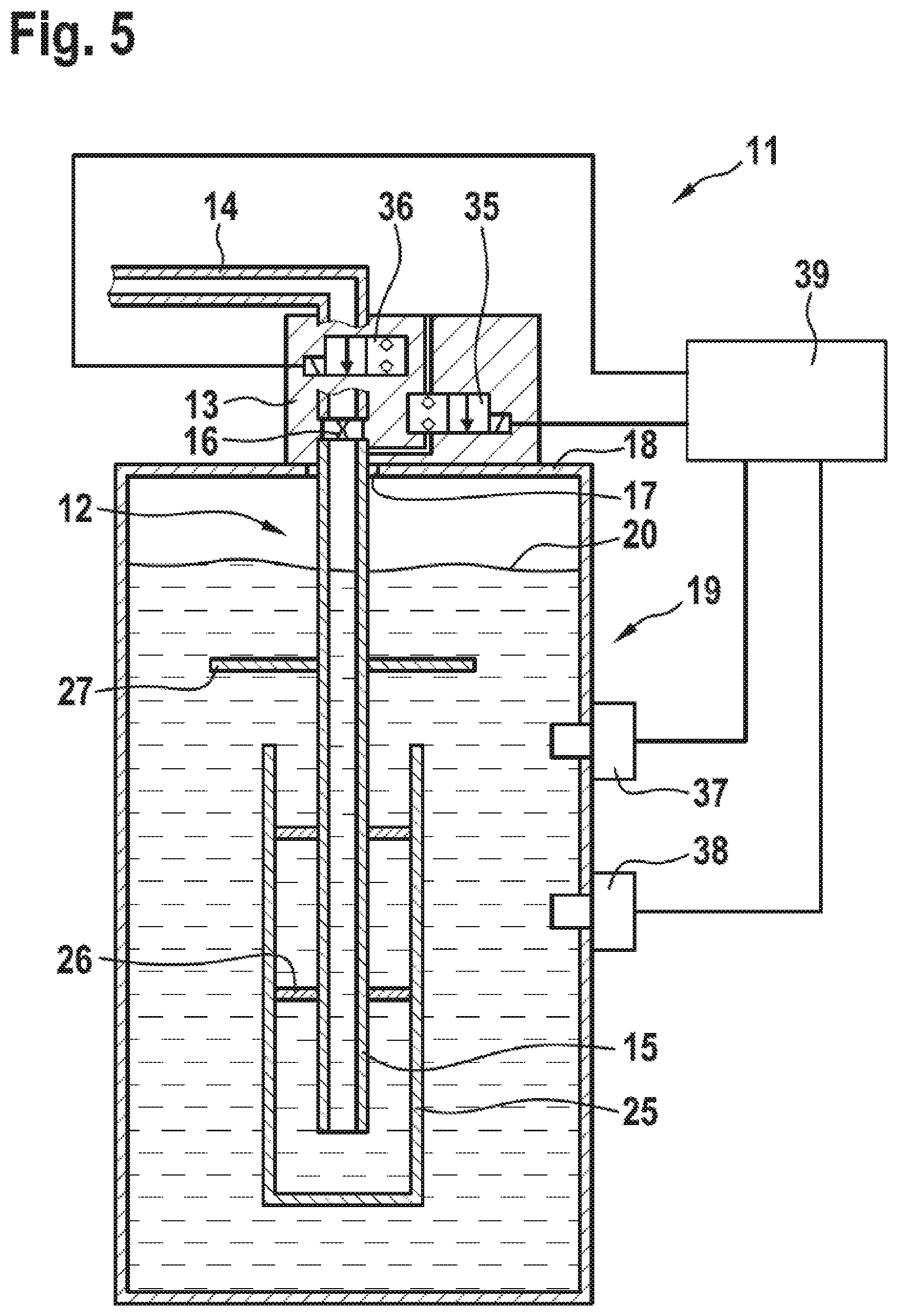
13. The device according to claim 1, further comprising a moisture sensor configured to determine a water content in the hydraulic oil, the device configured to be operated in dependence upon the determined water content.
14. The device according to claim 1, further comprising an oxygen sensor configured to determine an air content in the hydraulic oil, the device configured to be operated in dependence upon the determined air content such that an oxygen partial pressure is between 160 mbar and 190 mbar.
15. A hydraulic unit, comprising: a tank; and a device configured to one or more of degas and dehydrate a hydraulic oil, the device inserted into an opening of the tank and including: a flow lance that includes a restriction site via which the hydraulic oil flows under a high pressure drop, and a flow duct configured as a pipe that is located downstream of the restriction site, wherein a quantity of the hydraulic oil that flows via the restriction site and a throughflow cross section of the restriction site are coordinated to one another such that a cavitation zone or supercavitation zone forms downstream of the restriction
D00000
D00001
D00002
D00003
D00004
D00005
D00006
D00007
XML
uspto.report is an independent third-party trademark research tool that is not affiliated, endorsed, or sponsored by the United States Patent and Trademark Office (USPTO) or any other governmental organization. The information provided by uspto.report is based on publicly available data at the time of writing and is intended for informational purposes only.
While we strive to provide accurate and up-to-date information, we do not guarantee the accuracy, completeness, reliability, or suitability of the information displayed on this site. The use of this site is at your own risk. Any reliance you place on such information is therefore strictly at your own risk.
All official trademark data, including owner information, should be verified by visiting the official USPTO website at www.uspto.gov. This site is not intended to replace professional legal advice and should not be used as a substitute for consulting with a legal professional who is knowledgeable about trademark law.