Motorized Skate
Artemev; Timur
U.S. patent application number 16/077193 was filed with the patent office on 2020-06-25 for motorized skate. The applicant listed for this patent is Timur Artemev. Invention is credited to Timur Artemev.
| Application Number | 20200197786 16/077193 |
| Document ID | / |
| Family ID | 55697637 |
| Filed Date | 2020-06-25 |


| United States Patent Application | 20200197786 |
| Kind Code | A1 |
| Artemev; Timur | June 25, 2020 |
MOTORIZED SKATE
Abstract
The present invention provides a motorized skate having a balance control system adapted to maintain fore-and-aft balance of a platform of the skate about a wheel arrangement. The wheel arrangement defines a pivot point for the platform. A motor arrangement is adapted to drive the wheel arrangement so as to allow for the balance control system to maintain fore-and-aft balancing of the platform about the wheel arrangement.
| Inventors: | Artemev; Timur; (Haslemere, Surrey, GB) | ||||||||||
| Applicant: |
|
||||||||||
|---|---|---|---|---|---|---|---|---|---|---|---|
| Family ID: | 55697637 | ||||||||||
| Appl. No.: | 16/077193 | ||||||||||
| Filed: | February 13, 2017 | ||||||||||
| PCT Filed: | February 13, 2017 | ||||||||||
| PCT NO: | PCT/GB2017/050380 | ||||||||||
| 371 Date: | August 10, 2018 |
| Current U.S. Class: | 1/1 |
| Current CPC Class: | A63C 2203/12 20130101; A63C 17/08 20130101; A63C 17/0073 20130101; A63C 17/12 20130101; A63C 17/262 20130101; A63C 2203/24 20130101; A63C 2203/44 20130101; A63C 2203/18 20130101 |
| International Class: | A63C 17/12 20060101 A63C017/12; A63C 17/08 20060101 A63C017/08 |
Foreign Application Data
| Date | Code | Application Number |
|---|---|---|
| Feb 12, 2016 | GB | 1602567.8 |
Claims
1. A motorized skate for a single foot, the motorized skate comprising: a platform adapted to support a single foot of a user; a coupling arrangement adapted to couple the foot of the user to the platform; a single wheel arrangement comprising at least one wheel, wherein each at least one wheel is arranged such that the wheel arrangement forms a single pivot point about which the platform is tiltable in a fore-aft direction; a motor arrangement adapted to drive the at least one wheel; and a balance control system adapted to maintain fore-aft balance of the platform about the wheel arrangement.
2. The motorized skate of claim 1, wherein the motor arrangement comprises: a first motor adapted to drive at least one wheel of the wheel arrangement; and a second motor adapted to drive at least one wheel of the wheel arrangement.
3. The motorized skate of claim 2, wherein: the wheel arrangement comprises a plurality of wheels; the first motor is adapted to drive a first wheel of the plurality of wheels; and the second motor is adapted to drive a second wheel of the plurality of wheels, wherein the first motor and the first wheel are independent of the second motor and the second wheel.
4. The motorized skate of claim 3, wherein during a turning manoeuvre: the first motor drives the first wheel at a first speed; and the second motor drives the second wheel at a second, different speed.
5. The motorized skate of claim 2, wherein the first and second motor is adapted to drive at least one wheel using a belt or chain.
6. The motorized skate of claim 5, wherein a respective rotating output of the first and second motor has a smaller diameter than an input interface of the wheel driven by the respective first and second motor.
7. The motorized skate of claim 1, further comprising a stowable stand adapted to be operable in at least a stowed configuration and a deployed position, wherein the stowable stand is less proximate to the platform when in the deployed configuration.
8. The motorized skate of claim 1, further comprising a battery unit mounted thereon, the battery unit being adapted to provide power to at least the respective motor arrangement.
9. The motorized skate of claim 8, wherein the battery unit is coupled to the platform.
10. The motorized skate of claim 1, further comprising a sensor arrangement adapted to detect a side-to-side tilting indication from the user and to generate a signal indicative of an intention to perform a turning manoeuvre based the detected side-to-side tilting indication.
11. The motorized skate of claim 1, further adapted to generate a control signal indicative of at least a current or historical control parameter of the motorized skate.
12. The motorized skate of claim 11, wherein the control signal indicates at least one of: a speed of the skate; a remaining battery level of the skate; a distance to another skate; an indication of balance of the platform of the skate; an orientation of the skate; an indication of intended use of the skate, a wind speed incident on the skate; the acceleration of the skate; the torque applied by the motor arrangement of the skate; and a current output power of the motor arrangement.
13. The motorized skate of claim 11, further comprising a communication arrangement adapted to communicate the control signal.
14. The motorized skate of claim 13, wherein the communication arrangement is further adapted to receive a control signal communicated by another motorized skate.
15.-17. (canceled)
18. The motorized skate of claim 1, further comprising a wheel arrangement positioning system adapted to adjust a position of the wheel arrangement with respect to the foot platform.
19. A motorized system comprising: a first motorized skate according to claim 1; and a second motorized skate according to claim 1.
20. The motorized system of claim 19, wherein the motor arrangement of the first skate comprises: a first motor adapted to drive a first wheel of the wheel arrangement of the first skate; a second motor adapted to drive a second wheel of the wheel arrangement of the first skate, the first motor and first wheel being independent of the second motor and second wheel, and wherein the motor arrangement of the second skate comprises: a third motor adapted to drive a first wheel of the wheel arrangement of the second skate; a fourth motor adapted to drive a second wheel of the wheel arrangement of the second skate, wherein, during a turning manoeuvre, the first motor drives the first wheel of the first skate at a first speed, the second motor drives the second wheel of the first skate at a second speed, the third motor drives the first wheel of the second skate at a third speed and the fourth motor drives the second wheel of the second skate at a fourth speed, wherein the first, second, third and fourth speeds are different from one another.
21. The motorized system of claim 19, wherein if the first motorized skate is unbalanced in the fore direction, and the second motorized skate is unbalanced in the aft direction, the motorized system generates a signal indicative of an intention to perform a turning manoeuvre.
22. The motorized system of claim 19, wherein the first skate and second skate are adapted to be releasably connectable together, so as to form a single unit.
23. The motorized skate of claim 14, further comprising a processing unit adapted to: obtain the received control signal; obtain a balance signal from the balance control system; and control the motor arrangement to drive the wheel arrangement based on at least the received control signal and the balance signal; wherein the balance control system is adapted to generate the balance signal based on a level of fore-and-aft balance of the platform.
24. The motorized skate of claim 1 wherein the orientation of the skate relative to a gravity force does not affect the operation of the balance control system.
25. The motorized skate of claim 1, wherein the balance control system is adapted to maintain a combined vector of all forces applied to the skate at a position of the single pivot point.
Description
FIELD OF THE INVENTION
[0001] This invention relates to the field of motorized footwear, and in particular to the field of motorized skates adapted to be worn by a user.
BACKGROUND OF THE INVENTION
[0002] The concept of a powered, motorized skate is well known in the prior art. In particular, it is known to provide skates having a motor with a controllable speed by means of a control device such as a handheld input interface. Typically, such skates have either a combustion engine or an electric motor adapted to drive a plurality of wheels of the motorized skate, where the engine or motor can be controlled by the user.
[0003] The concept of a skating system having a primary skate and a secondary skate is known. In such arrangements the movement of the primary skate can be controlled by the user, where information related to that movement is passed to the secondary skate. This information is used by the secondary skate so as to reciprocally move in response. In typical examples, the rider positions the primary skate in front of the second skate so as to balance and control the skating system.
SUMMARY OF THE INVENTION
[0004] The invention is defined by the claims.
[0005] According to an aspect of the invention there is provided a motorized skate for a single foot, the motorized skate comprising: a platform adapted to support a single foot of a user; a coupling arrangement adapted to couple the foot of the user to the platform; a single wheel arrangement comprising at least one wheel, wherein each at least one wheel is arranged such that the wheel arrangement forms a single pivot point about which the platform is tiltable in a fore-aft direction; a motor arrangement adapted to drive the at least one wheel; and a balance control system adapted to maintain fore-aft balance of the platform about the wheel arrangement.
[0006] The balance control system of the motorized skate maintains a balance of the platform of the skate, for example, relative to a ground surface. That is to say, as the platform undergoes an attempted tilt in the fore or aft direction about the wheel arrangement (e.g. in response to a shift in a user's weight) the balance control system may attempt to address the unbalancing of the platform by accelerating the at least one wheel of the wheel arrangement forward or backwards. Thus, a balance control system employed by an embodiment may be arranged to maintain fore-aft balance by controlling the operation of an associated motor.
[0007] Embodiments thereby provide a motorized skate that is self-balancing in the fore-aft direction about a wheel arrangement. In particular, the wheel arrangement defines a single pivot point about which a platform of the skate may rotate in a fore-aft direction. The motorized skate is self-balanced about this pivot point. The self-balancing capability enables the propulsion of a user/rider in a controllable manner by the user/rider manipulating the fore-aft balance of a platform of the skate upon which they stand. Embodiments may thereby provide a user/rider with a significant degree of freedom or manoeuvrability.
[0008] Provision of a single pivot point provides an improved level of control to a user, with a greater degree of feedback for their movement. In particular, the tilting of the platform about the single pivot point may provide an intuitive and enjoyable way for a user to control their movement. In particular, it is recognised that a user may unbalance the platform so as to easily control the movement and speed of the motorized skate.
[0009] Proposed embodiments relate to a motorized skating system comprising a pair of such motorized skates. It may be understood that one motorized skate of such a motorized skating system may be substantially independent from the other motorized skate, such that an attempted tilt of the platform of the motorized skate need not cause a corresponding movement or tilt in the other skate. That is to say, two skates can self-balance independently from one another.
[0010] As used herein, the term "at least one wheel" refers to any wheel or element that is, during use, in contact with the floor or a ground surface. By way of example, a wheel may comprise a pneumatic tyre, a hubless wheel or even a roller. Other suitable rotatable structures suitable for acting as a wheel will be well known to the person skilled in the art.
[0011] In some embodiments, the motor arrangement comprises a first motor adapted to drive at least one wheel of the wheel arrangement and a second motor adapted to drive at least one wheel of the wheel arrangement.
[0012] Provision of a plurality of motors in this manner allows for at least a degree of redundancy, as failure of a single motor will not necessarily prevent further usage of the skate. The use of more than one motor also provides a greater deal of precision with respect to the movement of the wheel arrangement (as both motors need not be used simultaneously or controlled in the same manner) and also provides an increased efficiency in power usage for the motors, as the amount of torque required by each of the at least two motors is reduced. Furthermore, standardized motors may be used to efficiently drive a respective skate, rather than a complex bespoke or custom motor. This may, for example, minimise the complexity or cost of the motorized skate.
[0013] In at least one further embodiment: the first motor is adapted to drive a first wheel of the wheel arrangement; and the second motor is adapted to drive a second wheel of the wheel arrangement, wherein the first motor and the first wheel are independent of the second motor and the second wheel.
[0014] In other words, wheels of the wheel arrangement may be controlled independently from one another, such that the balance control system has an improved choice in how to control the wheel arrangement to account for an unbalancing of the platform of the skate. In other examples, the wheels may be controlled independently so as to account for a control, steering, battery power, energy recovery or directional stability of the skate.
[0015] In some further embodiments, during a turning manoeuvre: the first motor drives the first wheel at a first speed; and the second motor drives the second wheel at a second, different speed. Optionally the direction of rotation of the first wheel may be opposite to the direction of rotation of the second wheel during a turning manoeuvre.
[0016] Optionally, the first and second motor of the motorized skate is adapted to drive the at least one wheel using a belt or chain.
[0017] Preferably, a respective rotating output of the first and second motor has a smaller diameter than an input interface of the wheel driven by the respective first and second motor.
[0018] In at least one embodiment, the motorized skate further comprises a battery unit mounted thereon, the battery unit being adapted to provide power to at least the motor arrangement.
[0019] The battery unit may be coupled to either an upper surface of the platform or a lower surface of the platform. In other embodiments, the battery unit is embedded within the platform.
[0020] In some embodiments, a user may attempt to tilt the platform from side to side so as to indicate an intention to perform a turning manoeuvre. The motorized skate may detect such a side-to-side tilting intention using a sensor arrangement, and generate a signal indicative of an intention to perform a turning manoeuvre based on the side-to-side tilting intention. In such an embodiment, in response to a side-to-side tilting intention, the motorized skate may perform a turning manoeuvre. In other words, the user may lean to a side, which may be sensed by the sensor arrangement (comprising, for example, a pressure sensor or a platform tilt detecting system). The motorized skate may then generate a signal indicative of an intention to perform a turning manoeuvre based on this sensed signal.
[0021] Optionally, the motorized skate is adapted to generate a control signal indicative of at least a current or historical control parameter of the skate. Such a control signal may, for example, be generated by a control sensor.
[0022] The control signal may indicate at least one of a speed of the skate; a remaining battery level of the skate; a distance to another skate; an indication of balance of the platform of the skate; an orientation of the skate (e.g. at least one of an x, y and z position of a skate); an indication of intended use of the skate, a wind speed incident on the skate; the acceleration of the skate; the torque applied by the motor arrangement of the skate; and a current output power of the motor arrangement.
[0023] The motorized skate may comprise a communication arrangement adapted to communicate, transmit or emit the control signal. The communication arrangement is optionally further adapted to receive an emitted control signal of another motorized skate.
[0024] In further such embodiments, the motorized skate is adapted to further comprise a processing unit adapted to: obtain the received control signal; obtain a balance signal from the balance control system; and control the motor unit to drive the at least one wheel based on at least the received control signal and the balance signal; wherein the balance control system is adapted to generate the balance signal based on a level of fore-and-aft balance of the platform.
[0025] The motorized skate may further comprise a stowable stand adapted to be operable in at least a stowed configuration and a deployed position, wherein the stowable stand is less proximate to the platform when in the deployed configuration.
[0026] Embodiments may provide a motorized system comprising two motorized skates as briefly described earlier. In particular, there may be provided a first motorized skate and a second motorized skate. The motorized system may be considered to be a motorized skating system.
[0027] Embodiments may therefore provide a motorized skating system having a high amount of manoeuvrability and agility. Each skate may be independent so as to allow for a user to easily and swiftly perform a turn with a minimal turning circle. As the balance control system of each skate may be independent from one another, there may be a reduction in the overall power consumed by the motorized skating system. The skating system advantageously permits for each skate to be independently operable from one another so as to allow the user of the skates a greater degree of freedom, for example, in performing tricks or stunts. The use of separable skates as described may, for example, allow a user to traverse difficult or uneven terrain, an obstacle or even steps.
[0028] There may be a skating system wherein the motor arrangement of the first skate comprises: a first motor adapted to drive a first wheel associated with the wheel arrangement of the first skate; a second motor adapted to drive a second wheel associated with the wheel arrangement of the first skate, the first motor and first wheel being independent of the second motor and second wheel. In such a skating system, the motor arrangement of the second skate may comprise: a third motor adapted to drive a third wheel associated with the wheel arrangement of the second skate; a fourth motor adapted to drive a fourth wheel associated with the wheel arrangement of the second skate, wherein, during a turning manoeuvre, the first motor drives the first wheel at a first speed, the second motor drives the second wheel at a second speed, the third motor drives the third wheel at a third speed and the fourth motor drives the fourth wheel at a fourth speed, wherein the first, second, third and fourth speed are different from one another.
[0029] In conceivable embodiments, each skate is adapted to learn from one another by, for example, combining data from the two units to determine how to improve overall control of the skating system.
BRIEF DESCRIPTION OF THE DRAWINGS
[0030] Examples of the invention will now be described in detail with reference to the accompanying drawings, in which:
[0031] FIG. 1A depicts a schematic view of a motorized skating system according to a first embodiment;
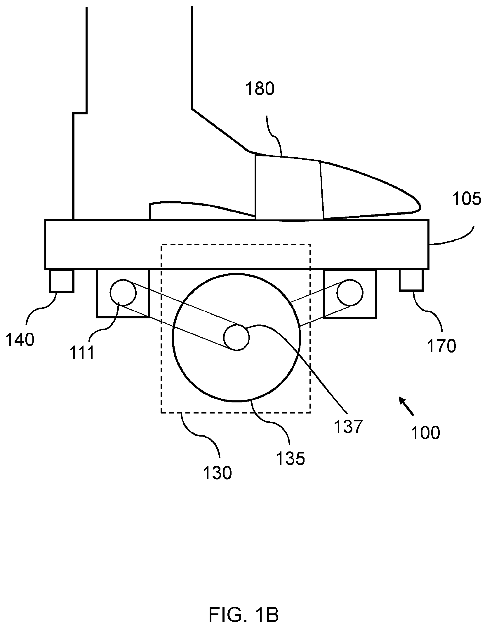
[0032] FIG. 1B illustrates a side view of the first skate for the motorized skating system according to the first embodiment.
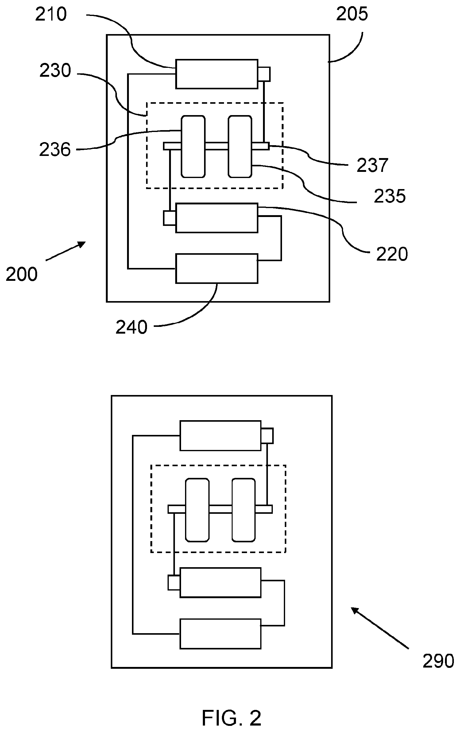
[0033] FIG. 2 depicts a schematic view of a motorized skating system according to a second embodiment;
[0034] FIG. 3 depicts a schematic view of a motorized skating system according to a third embodiment;
[0035] FIG. 4A depicts a schematic view of a motorized skating system according to a fourth embodiment;
[0036] FIG. 4B illustrates a side view of a first skate for the motorized skating system according to the fourth embodiment; and
[0037] FIGS. 5A-5C illustrate a motorized skate according to an embodiment.
DETAILED DESCRIPTION OF THE EMBODIMENTS
[0038] The present invention provides a motorized skate having a balance control system adapted to maintain fore-and-aft balance of a platform of the skate about a wheel arrangement. The wheel arrangement defines a pivot point for the platform. A motor arrangement is adapted to drive the wheel arrangement so as to allow for the balance control system to maintain fore-and-aft balancing of the platform about the wheel arrangement.
[0039] Embodiments of a motorized skate will be described in the context of a motorized skating system formed of a pair of motorized skates. It is readily apparent that the same inventive principles and concepts could be applied to a single skate, such that a single skate can be provided independently of another skate.
[0040] FIGS. 1A and 1B schematically depict a motorized skating system 1 according to a first embodiment. FIG. 1A identifies an underside view of the skating system, whereas FIG. 1B depicts a side view of a single motorized skate of the motorized skating system. The motorized skating system comprises a first motorized skate 100 and a second motorized skate 190. Thus, FIGS. 1A and 1B also illustrate a motorized skate according to an embodiment.
[0041] Each motorized skate comprises a platform 105 adapted to support a respective foot of a user.
[0042] The platform 105 is tiltable about a single wheel arrangement 130, which here comprises a single wheel 135 positioned on an axis 140. In particular, the wheel arrangement 130 defines a single pivot point (here the axis 140) about which the platform may tilt (when the wheel arrangement is in contact with a ground surface). The wheel arrangement may define a single or sole axis of rotation about which the platform 105 may tilt in a fore-aft direction. That is, the wheel arrangement may thereby define a single point or axis (i.e. a single pivot point or single pivot axis) about which the platform may tilt both in a forward direction and in a rearward direction. In particular, such a single pivot point or pivot axis is the only or sole pivot point/axis of the motorized skate. Thus, the motorized skate may not be associated with any other pivot points or pivot axes about which the platform may rotate in a fore-aft direction when the wheel arrangement is in contact with the ground surface.
[0043] The single wheel arrangement 130 may comprise all the wheels connected to the platform 105, such that the single wheel arrangement is the sole or solitary wheel arrangement of the motorized skate 100. The single wheel arrangement 130 may, at least when the motorized skate 100 is in motion, wholly and independently couple the platform 105 to a ground surface, so as to wholly support the platform and the user thereon. The platform 105 may thereby freely tilt about the single wheel arrangement 130.
[0044] In embodiments, the platform of the first 100 and second 190 motorized skate is substantially the same, such that a user may place either his left or right foot on the platform of either skate. In other embodiments, the platforms of the first and second skate are different, such that a user may only place his left or right foot on a specific skate. By way of example, the platforms of the skates may be adapted such that the user may only comfortably place his left foot on the first skate, and his right foot on the second skate. In other words, the platform of each respective skate may be shaped so as to be associated with a different foot of the user (e.g. left and right versions). In at least one conceivable embodiment, the platform may be partially flexible so as to, for example, mould to a user's foot. It may be understood that respective platforms are adapted to support only a single foot of a user, such that, in use, both feet are not to be positioned on any one platform.
[0045] A wheel may be formed from one or more tyres and/or hubs that are coupled together (via a differential, for example). For example, an embodiment may comprise a hubless wheel having a hubless rim with a plurality of separate tyres fitted thereon. Alternatively, an embodiment may comprise a hubless wheel formed from a plurality of hubless rims (each having a respective tyre fitted thereon), wherein the plurality of hubless rims are coupled together via a differential bearing arrangement. A yet further embodiment may comprise a wheel having a single rim and hub with a plurality of separate tyres fitted thereon. A yet further embodiment may comprise a wheel formed from a plurality of hubs and rims (each having a respective tyre fitted thereon), wherein the plurality of hub and rims are coupled together via a differential bearing arrangement.
[0046] Each motorized skate comprises a motor arrangement having a first motor 110 and a second motor 120. Of course, in some embodiments the motor arrangement may comprise only a single motor. The motor arrangement is adapted to drive the wheel arrangement 130, and in particular to rotate the single wheel 135.
[0047] The first and second motor in the motor arrangement are adapted to drive the single wheel of the wheel arrangement so as to control the speed of the wheel arrangement.
[0048] In at least one embodiment, the first motor 110 comprises an output drive 111 which rotates at a first speed (i.e. is a rotating output). The output drive is coupled to an engaging mechanism 137 of the wheel arrangement 135 by, for example, a differential, belt, chain, gear or cog mechanism. In other words, the output drive is coupled to an input arrangement of the wheel arrangement, so as to provide an input rotation force to a wheel of the wheel arrangement. As the output drive of the first motor rotates, so the wheel is adapted to rotate.
[0049] The use of a belt, chain or gear mechanism in this manner may allow for the motor to rotate at its most efficient or optimal speed, whilst not necessarily rotating a wheel of the wheel arrangement at the same said speed. This could allow, by way of example, for an improved efficiency of the skating system as well as a reduced power and/or an increased torque to drive the wheel arrangement.
[0050] Similarly, the second motor 120 may also comprise a respective output drive which rotates at a second speed. The output drive of the second motor may also be coupled to the same or different engaging mechanism of the wheel arrangement so as to control the rotation of the wheel.
[0051] Simply for the purposes of further insight, a wheel for a motorized skate may be a pneumatic tyre of 75 mm in diameter. To attain a top speed of around 21 kmh or 13.5 mph (in a preferable embodiment of the skating system), such a tyre need only rotate at approximately 1500 RPM (revolutions per minute). Motors that could be used typically have an optimal rotation of approximately 3000-6000 RPM. Thus a gearing or belt ratio of between 2:1 or 4:1 (or higher) is necessary to ensure the wheel rotates at an appropriate speed.
[0052] A balance control system 140 is provided to each respective skate 100, 190 so as to control the respective motor arrangement of that skate, that is the first motor 110 and the second motor 120, to thereby control the rotation of the single wheel 135 of the wheel arrangement. The balance control system is adapted to maintain fore-and-aft balance of the platform about the single pivot point defined by the wheel arrangement.
[0053] By way of example, the balance control system 140 of each motorized skate may include a gyroscope, accelerometer, force vector sensor, sonar or ultrasound sensor, or other proximity sensing system (not shown) which senses forward and backward tilt of the platform about the wheel arrangement, and optionally in relation to the ground surface, and regulates the motor arrangement accordingly to maintain a fore-aft balance of the platform. The platform may be maintained substantially horizontal with respect to the ground surface.
[0054] In this way, the user is provided a way of controlling the acceleration and deceleration of the motorized skate by varying the pressure applied to various areas of the platform. It also enables each motorized skate to self-regulate its balance with respect to the platform rotation about the wheel arrangement in the fore-and-aft plane.
[0055] The balance control system may take into account, for example, additional forces rather than that of simply gravity. For example, the balance control may take a current friction or centrifugal force into account when determining the fore-aft balance of the platform. In some embodiments, the balance control system may attempt to bring a vector of combined forces towards substantially the centre of the wheel arrangement (e.g. by driving the wheel arrangement to move the platform backwards or forwards), such that the platform may be balanced with respect to the wheel arrangement. Thus, the vector of combined forces applied to the platform may be brought to a position of the single pivot point. In particular, the balance control system is adapted to maintain a combined vector of all forces applied to the skate at a centre of the wheel arrangement. Such forces may be detected, for example, using an accelerometer, gyrometer, pressure sensor, proximity sensor and so on. It will be appreciate that some such force detection systems, e.g. and accelerometer, may be indiscriminate in determining forces applied (e.g. it detects both a gravitational force and a centripetal force in a same manner). This may allow, for example, the balance control system to maintain a fore-aft balance of the platform even on non-horizontal, sloped or even vertical surfaces (such as a "Wall of Death").
[0056] In other words, each skate is adapted to attempt to maintain a substantially horizontal (relative to a ground surface) platform of that motorized skate through monitoring the fore-and-aft balance of that platform about the wheel arrangement. Each skate is individually adapted to react to an unbalancing in the forward or reverse direction, relative to the direction of the skate. The ground surface need not be understood to be simply a conventional flat floor, but may rather by, for example, a slope, ramp, loop, sphere and so on. The orientation of the motorized skating system relative to the surface of the planet (e.g. Earth) may be immaterial to the fore-aft balance system, that is to say that the balance control system may be adapted to as to account for a gravitational force. By way of example, a user may wish to ride the motorized system in a `Wall of Death` having substantially vertical boards on which the motorized system is intended to ride, and the balance control system may attempt to maintain a substantially horizontal platform relative to the vertical wall (where the user is held on the wall by friction and centrifugal forces). It will be clear that, in some embodiments, if the surface on which the motorized skating system is not flat, the motorized skating system may attempt to maintain a fore-aft balance of the platform relative to an area of the ground surface on which the wheel arrangement is positioned. In other or further embodiments, the balance control system of the respective skate may take the absolute orientation (i.e. the orientation relative to the planet) of the motorized skating system into when maintaining the fore-aft balance of the platform.
[0057] Of course, the `Wall of Death` scenario is only a primitive example of a multitude of possible, complex surfaces which the motorized skate may be configured to operate. Other surface includes, for example, skate park surfaces, spheres or other rough or wave-like surfaces.
[0058] In some embodiments, the skate may be adapted to predict or detect an upcoming surface (e.g. using a camera or LIDAR system or algorithms based on a current surface) and determine how to control a fore-aft balance of the skate based on the upcoming surface.
[0059] From the foregoing explanation, it will be apparent that the balance control system is adapted to maintain a fore-aft balance of the platform about the wheel arrangement with respect to all forces applied by a foot of the user to the platform. These forces may comprise a combination of a gravitational force (due to a user's weight), a centripetal force, a force applied by a user and so on. In particular, a combined force vector may be maintained substantially toward a position of the pivot point or wheel arrangement.
[0060] It may be otherwise understood that the platform may tilt about the wheel arrangement and relative to a ground surface so as to cause an unbalancing of the platform in at least the fore-and-aft directions. The balance control system may then attempt to address the unbalancing of the platform by, for example, accelerating the at least one wheel of the wheel arrangement forward or backwards. It is therefore readily apparent that a user of a motorized skate can control the speed of the motorized skate by adjusting the amount of which the platform is attempted to be tilted, so as to control the extent to which the balance control system attempts to maintain the fore-and-aft balance of the platform.
[0061] It should be apparent that the balance control system 140 is adapted to maintain the fore-aft balance of the platform 105 of the motorized skate 100 about the wheel arrangement (i.e. the single pivot point) by controlling the motor arrangement (first motor 110 and second motor 120) so as to control the driving, speed or even direction of the wheel 135.
[0062] The motorized skate 100 comprises a coupling arrangement 180 adapted to engage a user's foot to the platform. By way of example, such a coupling arrangement may comprise straps, as illustrated, buckles, laces and so on. It should be understood that references to foot, as used throughout the description, are intended to be interpreted as referring to a user's foot, ankle, toes, lower legs, footwear (such as that worn by a user) or items which may be attached to a user's foot.
[0063] The coupling arrangement may be adapted to be automatically switchable between at least a coupled mode, in which the foot of the user is coupled to the support such that removal of the foot from the support is restricted, hindered, prevented or even impossible, and an uncoupled mode, in which removal of the foot from the support is permitted or possible.
[0064] In particular, the coupling arrangement may be adapted to switch between at least the coupled mode and the uncoupled mode in response to a usage signal generated by a usage detection system (not shown). The usage signal may be representative of or associated with at least a usage of the wheeled transportation device. By way of example, the usage signal may comprise an indication of intent to begin or end use of the wheeled transportation device or a parameter of the motorized skate (e.g. speed, acceleration, distance travelled, time since power on and the like).
[0065] The coupling arrangement may thereby comprise, for example, auto-retracting straps, magnetic arrangements or other retractable couplers.
[0066] In another example, the coupling arrangement may be adapted to switch between at least the coupled mode and the uncoupled mode in response to a user input signal (e.g. from a mobile device).
[0067] Thus, the coupling arrangement may be adapted to, without a manual input from a user, switch between a coupled mode and an uncoupled mode so as to releasably secure the user's foot to the platform. Of course, in other embodiments the coupling arrangement may be adapted to receive a manual input from a user so as to couple and decouple accordingly, such as a user undoing a buckle or loosening a strap.
[0068] Embodiments allow for a motorized skating system having two independently controllable skates, to provide the user with a high amount of manoeuvrability and agility. The independence of each skate may allow for a user to easily and swiftly perform a turn with a minimal turning circle. The skating system advantageously permits for each skate to be independently operable from one another so as to allow the user of the skates a greater degree of freedom. The use of separable skates in this manner may, for example, allow a user to traverse difficult terrain, obstacle in a terrain or steps.
[0069] Provision of a plurality of motors for controlling the rotation of the wheel arrangement, as above described, provides an increased efficiency in power distribution as well as an improved efficiency in control of the movement of the wheel arrangement.
[0070] Each motorized skate further comprises a battery unit 170 adapted to provide power to at least the motor arrangement, and optionally also to the balance control system.
[0071] In the present embodiment, the wheel arrangement (i.e. the single wheel) is positioned directly beneath the platform, that is, beneath the sole of the foot. In other embodiments, the single wheel may be positioned to the side of the platform (e.g. coupled to the left or right side of the platform). In yet other embodiments, the wheel is positioned in a cut-out of the platform, such that the platform partially covers a side of the wheel. The user's foot may be supportable by the platform in any position relative to the wheel arrangement, by way of example, the user's foot may be positioned to a left side of the platform, whereas the wheel arrangement be positioned to a right side of the platform. Other positions of the wheel arrangement relative to the platform and the user's foot will be readily apparent to the person skilled in the art.
[0072] It will be clear that the platform is adapted to rotate about the wheel arrangement, and in particular, about a pivot point defined by the wheel arrangement.
[0073] Presently, the first and second motor of the motor arrangement are respectively positioned at the fore and aft ends of the motorized skate (i.e. positioned and the front and rear of the skate, such that one motor is positioned towards the toe end of the motorized skate, and the other motor is positioned towards the heel end of the skate). This allows for an increased ease in the self-balancing of the motorized skate, as the weight of the motor arrangement is distributed across the motorized skate.
[0074] Conceivably, the motor arrangement could be positioned towards the same end of the motorized device. This could be used, for example, to counter-balance a battery unit positioned at an opposing end of the motorized skate.
[0075] In embodiments, the motor arrangement is mounted on a lower surface of the platform. In other embodiments, the motor arrangement is housed within or above the platform.
[0076] FIG. 2 schematically depicts a motorized skating system 2 according to a second embodiment of the invention. The motorized skating system comprises a first motorized skate 200 and a second motorized skate 290.
[0077] As in the previous embodiment, each motorized skate comprises a respective platform 205 adapted to support the foot of the user.
[0078] Similarly, each motorized skate comprises a motor arrangement having a first motor 210 and a second motor 220 adapted to drive a wheel arrangement 230. The wheel arrangement comprises a first wheel 235 and a second wheel 236. The first wheel and the second wheel are connected or coupled together by a single axle 237, shaft or differential, such that the first and second wheels rotate together with one another. That is to say, as the first wheel rotates, so the second wheel rotates.
[0079] Here the position of the single axle 237 defines the position of the pivot point about which the platform 205 may rotate in a fore-aft direction. Thus, an axis about which each wheel of the wheel arrangement rotates may define a position of the pivot point. The wheels may thereby be positioned side-by-side along the axis defining the pivot point.
[0080] The first and second motor (i.e. the motor arrangement) is adapted to rotate the first and second wheel together. In other words, the first and second motor together drive the first and second wheel by, for example, rotating an engaging mechanism on the single axle 237, such that the first and second wheel are controlled by both the first and second motor. The first and second wheels are therefore not independent from one another.
[0081] As previously described, a balance control system 240 is adapted to maintain fore-aft balance of the platform 205 about the wheel arrangement 230 of the motorized skate 200 by controlling the motor arrangement (first motor 210 and second motor 220) so as to together control the driving or speed of rotation of the first wheel 235 and the second wheel 236.
[0082] Provision of a plurality of motors in this manner advantageously allows for a degree of redundancy in the motorized skating system, such that if a single motor fails, the motorized skate may still operate. Furthermore, a plurality of motors per motorized skate also provides an increased efficiency in power distribution as well as an improved efficiency in control of the movement of the wheel arrangement.
[0083] Provision of a plurality of wheels positioned within a single axis provides the advantage of a reduction in the likelihood of unwanted side-to-side (e.g. left or right) tilting, such that the user is less likely to fall or stumble sideways.
[0084] FIG. 3 schematically depict a motorized skating system 3 according to a third embodiment of the invention. The motorized skating system comprises a first motorized skate 300 and a second motorized skate 390.
[0085] As in the previous embodiments, each motorized skate comprises a respective platform 305 adapted to support the foot of a user. As previously described, the platform may be tiltable about a wheel arrangement and relative to a ground surface in at least the fore-and-aft directions.
[0086] Similarly, each motorized skate comprises a motor arrangement having a first motor 310 and a second motor 320.
[0087] However, in the present embodiment, the wheel arrangement 330 comprises a first wheel 331 and a second wheel 332, each wheel being adapted to rotate independently from one another. Thus, by way of example, each wheel may be positioned on a separate axle, such that rotation of the first wheel does not affect rotation of the second wheel.
[0088] The first and second wheels 331, 332 are positioned in a single axis 33X, such that the wheels are adapted to be positioned alongside one another, so that they are all oriented in the same direction and side-by-side in a single row. In other words, each wheel is positioned along the same (imaginary) axis. This advantageously allows the platform of each motorized skate to be readily unbalanced, as it will be apparent that the platform may easily rotate about the single axis defined by the wheels.
[0089] The single axis defines the single pivot point about which the platform of the motorized skate may rotate. In particular, the single axis is an axis about which each of the respective wheels rotates.
[0090] In embodiments, each wheel is axle-less, but may still, for example, be positioned in the same axis.
[0091] It should be clear that in a single axis is intended to mean a single axis when a respective skate is viewed from above, such that a skate where the wheels have tilted such that their axles are no longer in line, is still be considered to have its wheels in the same single axis (e.g. if the first and second wheel tilt in response to a turning manoeuvre). Similarly, at rest, when the first and second wheels have an axle, the axles of the first and second wheel may be substantially in line with one other. That is, when no attempted tilting of the platform is performed, the axles can be considered to form a single virtual axle. It should also be understood that the wheel should be considered to be in the same axis when they are aligned side-by-side, next to one another, as the respective skate moves solely in the fore or solely in the aft direction on a level ground surface.
[0092] It will be appreciated that the single axis is intended to run from one side of the skate to the other side of the skate (i.e. in the port and starboard direction), such that the axis is not aligned in the fore and aft directions of the skate. In other words, the axis typically spans the width of the platform, and not along the length.
[0093] The first motor is adapted to drive the first wheel, and the second motor is adapted to drive the second wheel. In other words, each wheel is associated with a respective motor, such that each wheel may be rotated independently by a respective motor.
[0094] It is therefore apparent that in embodiments the first and second wheel may be independently controlled (with respect to speed, torque, RPM and so on), have a respective independent suspension and possibly tilt independently from one another. This similarly allows the different wheels to be rotated at different speeds.
[0095] As before, the motor arrangement is adapted to be controlled by a balance control system 340 so as to maintain fore-and-aft balance of the platform by controlling the rotation of the wheel(s) of the wheel arrangement. In other words, the balance control system is adapted to control the independent movement of the first wheel and the independent movement of the second wheel so as to balance the platform of the motorized skate.
[0096] Provision of independently rotatable wheels controlled by respective motors in this manner advantageously allows an improved turning circle and an improved control. By way of example, during a turning manoeuvre, the first wheel may rotate at a first speed, and the second wheel may rotate at a second, different speed. If, for example, the first speed is greater than the second speed, the motorized skate will rotate in the direction of the second wheel.
[0097] In other words, the different wheels may be adapted to be rotatable at different speeds. Conceivably, each motorized skate could be considered to operate in a plurality of modes including at least a `normal travel` mode, in which the wheels of the motorized skate rotate together at the same speed, and a `turning travel mode` in which the wheels of the motorized skate rotate at different speeds so as to rotate the motorized skate.
[0098] In such embodiments, each motorized skate may be able to undergo torque vectoring or speed vectoring.
[0099] In some embodiments, the first wheel 310 is associated with a first suspension arrangement, and the second wheel 320 is associated with a second suspension arrangement, such that each wheel has its own independent suspension system. This may allow, for example, for a single wheel to run over an obstacle without affecting another wheel in the wheel arrangement. The first and second suspension arrangement may respectively comprise a spring or other known dampening mechanisms.
[0100] In some embodiments, the platform 305 of each motorized skate is adapted to tilt in the left and right directions, that is, be tiltable in the port and starboard directions towards the sides of the platform. It is therefore apparent that in such embodiment, the platform may tilt in at least four directions: forward and backward (i.e. fore and aft) as well as in both directions sideways (i.e. left and right). The balance control system may be adapted to determine this side-to-side tilting and determine that the user intends to perform a turning manoeuvre or requires a turning movement. Based on this side-to-side tilting (i.e. in response to a user leaning sideways) each motorized skate may perform a turning manoeuvre so as to rotate a direction is which a user faces. Preferably, the platform is adapted such that the platform is free to tilt in any direction (e.g. diagonally). Such a diagonal tilt may, for example, be indicative of both a forward movement and a turning movement. Such a tilting platform is implementable in any herein described embodiment. Of course, it will be understood that a user tilting such a platform is indicative of a user's intention to tilt.
[0101] In other embodiments, there may be a pressure sensor system positioned on the foot platform, the pressure sensor system being adapted to determining a tilting movement of the user, indicative of an intended side-to-side tilt of the platform. The balance control system may similarly generate a signal indicative of an intention to perform a turning manoeuvre, and each motorized skate may perform a turning manoeuvre based on this signal. In other words, each motorized skate may be adapted to detect when a person is attempting to tilt the platform from side-to-side (but, for example, the platform is unable to perform such tilting) and generate a signal based on this detected intention or desire. This embodiment may advantageously decrease the complexity of the side-to-side tilt sensing system, whilst still allowing a user to indicate an intention or desire to perform a turn by leaning from side-to-side.
[0102] In one such embodiment, the platform 305 is mounted on springs adapted to allow the platform to tilt in the at least four directions. This advantageously permits the platform to be suspended relative to the wheel arrangement and/or the ground surface so as to increase the comfort of ride for a user.
[0103] In such embodiments, it may be particularly advantageous for the first and second wheels to be associated with a respective separate suspension arrangement, such that as a user leans on the platform (and thereby causes a leaning of at least one wheel), both wheels may still remain in contact with a ground surface so maintain a drive against the ground surface.
[0104] The balance control system may be adapted to detect a rotation speed of the first wheel and a rotation speed of the second wheel, so as to calibrate the motor arrangement to rotate the wheels at an appropriate speed so as to maintain a balancing of the platform of the respective motorized skate.
[0105] In the above described embodiments the wheel(s) of the wheel arrangement of the motorized skate are generally positioned centrally with respect to the fore and aft directions (i.e. generally in the centre of the skate). This advantageously allows for an increased efficiency of the skate, as the platform is naturally more evenly balanced such that the balance control system has a reduced required output to maintain the balance of the platform. Of course, the wheel arrangement may be positioned anywhere in the motorized skate with respect to the platform.
[0106] FIG. 4A depicts a schematic representation of a motorized skating system 4 according to a fourth embodiment of the inventive concept. As in previous embodiments, the motorized skating system comprises a first motorized skate 400 and a second motorized skate 490. FIG. 4B depicts a side view of the first motorized skate 400 according to the fourth embodiment.
[0107] In the usual manner, each motorized skate comprises a platform 405 adapted to support a foot of the user. In a similar way to the third embodiment, each motorized skate comprises a motor arrangement having a first motor 410 and a second motor 420, each motor being adapted to drive a single wheel, being the first wheel 431 and the second wheel 432 of the wheel arrangement 430 respectively.
[0108] As before, the motor arrangement is adapted to be controlled by a balance control system 440 so as to maintain fore-and-aft balance of the platform by controlling the rotation of the wheel(s) of the wheel arrangement. In other words, the balance control system is adapted to control the independent movement of the first wheel and the independent movement of the second wheel so as to balance the platform of the motorized skate.
[0109] However, in the present embodiment, the first wheel 431 and the second wheel 432 are positioned so as to not lie within the same axis. In other words, the first and second wheels are not aligned to lie alongside one another, side-by-side.
[0110] However, the first wheel 431 and second wheel 432 may be considered to lie substantially along the same axis, such that they continue to define a single pivoting point about which the platform rotates.
[0111] By way of example, the wheels may be offset from one another so as to account for the natural balance of a user or the natural shape of a foot. It will, however, be understood that due at least to the natural shape of the foot or balance of the user, the wheel arrangement continues to act as a single pivoting point about which the platform may rotate.
[0112] As before, the wheels of each respective skate may be associated with a respective suspension system so as to allow each wheel to remain in contact with a ground surface. This may be of particular advantage when the skate(s) are passing over rough or uneven terrain.
[0113] In some embodiments, each motorized skate of the motorized skating system may be adapted to pass information about the respective motorized skate to the other motorized skate of the motorized skating system. This information could be passed by, for example, a communication arrangement mounted on each motorized skate. Information about the motorized skate may, for example, be generated by a control sensor adapted to generate an indication of a current or historical control parameter of the respective motorized skate. By way of example, the information passed may comprise any one or more control parameters associated with at least one of: a speed of the respective skate; a remaining battery level of the respective skate (in a battery unit of the respective skate, for example); a distance to the other skate of the skating system (measured by, for example, a signal strength between the skates or a proximity sensor directed toward the other skate and so on); an indication of balance of the platform of the respective skate; an orientation of the respective skate (e.g., relative to a gravitational force or to a ground surface); an indication of intended use of the respective skate (e.g. whether the user intends to stop, start or pause use of the skate, or whether the user wishes to perform a turning manoeuvre and so on), a wind speed incident of the respective skate; the acceleration of the respective skate; the torque applied by the motor arrangement of the respective skate; and a current output power of the motor arrangement (i.e. how much power is output to the wheel arrangement).
[0114] In at least one embodiment, the balance control system of each skate is adapted to take into account the generated and/or received information about the motorized skate(s) in determining in what manner to control the motor arrangement. For example, if the first skate indicates an intention to turn, this information may be passed to the second skate, such that the balance control system of the second skate may determine to perform a turning manoeuvre with the second skate. In another example, if the first skate indicates that a battery level of the first skate is low, the second skate may adjust the driving of the motor arrangement to a maximum allowable speed.
[0115] In embodiments, the motorized skating system comprises a first skate having a first motor adapted to drive a first wheel and a second motor adapted to drive a second wheel, the first motor and first wheel being independent of the second motor and second wheel. The motorized skating system also comprises a second skate having a third motor adapted to drive a third wheel (associated with the second skate); and a fourth motor adapted to drive a fourth wheel (associated with the second skate). In response to a turning manoeuvre being indicated by at least one of the first and second skates (e.g. in response to a user leaning), the first motor drives the first wheel at a first speed, the second motor drives the second wheel at a second speed, the third motor drives the third wheel at a third speed and the fourth motor drives the fourth wheel at a fourth speed, wherein the first, second, third and fourth speed are different from one another. Thus, by way of example, if a first wheel is a leftmost wheel, and the fourth wheel is the rightmost wheel (relative to a user), in response to a left turn manoeuvre, the first wheel may be rotated more slowly than the fourth wheel. In one embodiment, information about the intent of the first and second skates may be passed between the first and second skates via respective communication devices so as to control the respective speeds of the wheels to allow control of the turning manoeuvre.
[0116] Although above embodiments describe skates having two motors and either one or two wheels, it will be readily apparent that the inventive concept can be expanded to incorporate any number of motors and wheels within a respective skate. By way of example only, a motorized skate of a motorized skating system according to an embodiment could comprise three motors and two wheels, wherein the wheels may be adapted to rotate either individually or together with respect to one another. In other conceivable embodiments, there may be provided three motors and three wheels, wherein each wheel rotates independently with respect to the others and is associated with a single respective motor. In other embodiments, there may be provided three motors and three wheels, wherein a first wheel is associated with only a first motor, and wherein a second and third wheel are associated with a respective second and third motor, wherein the first wheel and first motor are independent of the second and third motor and wheel, but wherein the second and third wheels rotate together, such that the second and third motors controls the rotation of the second and third wheels.
[0117] The motor arrangement of a motorized skate of the motorized skating system may comprise additional motors (i.e. more than two) adapted to drive the wheel arrangement. An increase in the number of motors may allow for a greater speed of the motorized skate, an increased redundancy, an improved control over the wheel arrangement, a greater number of independent wheels allowing for an improved turning circle (for example), and/or allow for motors having different optimal efficiency rotating speeds to be provided.
[0118] In at least one conceivable embodiment, the motor arrangement may comprise a plurality of motors adapted to drive the wheel arrangement, wherein the motor arrangement may switch between active motors (i.e. currently driving motors) based on a characteristic of the motorized skate (e.g. battery level, speed, required RPM of wheels, environment, slippage of wheels). This may allow a more efficient motorized skating system, wherein the most appropriate motor drives the wheel arrangement at the most suitable or appropriate time. In some circumstances, the switching of the motor may depend on the speed of the device, such that the motor(s) that has the nearest or most efficient associated RPM with respect to the RPM or speed of the wheel arrangement can be used to drive the wheel arrangement.
[0119] In some conceivable embodiments, the motor arrangement of each motorized skate may comprise only a single motor adapted to drive the wheel arrangement. Such a system would still provide for independently operable skates and continue to provide the user with a greater degree of freedom. In some such embodiments, each skate may comprise more than one wheel, each wheel being connected by a controllable differential so as to control the rotation of each wheel so as to allow for control of the turning circle of the motorized skating system (by, for example, rotating the wheels at different speeds by controlling the differential). Such a differential may comprise a controllable gearing system, for example, so as to allow for selection of a ratio in the rotation speeds of the more than one wheel.
[0120] It should be readily understood that in the above described embodiments, the one or more wheels of the wheel arrangement may be positioned to the side of the foot platform, mounted below the foot platform, embedded within the foot platform and so on.
[0121] The orientation of the respective foot of the user to the respective foot platforms of the skates may be in any direction relative to the fore-aft direction of the skates. By way of example, with reference to a single skate, the user may stand with his foot in line with the fore-aft direction of the foot platform, such that forward and backward leaning of the user unbalances the foot platform in the fore and aft direction respectively. In other embodiments, the user's foot may be positioned perpendicular to the fore-aft direction of the respective skate, such that a side to side leaning of the user may unbalance the skate in the fore-aft direction.
[0122] In at least one embodiment, a pair of motorized skates are adapted to be connectable with one another so as to form a single device. In other words, the first skate may be physically connected or coupled to the second skate. When connected, each skate may still be able to tilt independently of the other. In other such embodiments, the skates maybe limited so as to only be able to tilt together with each other, such that as the foot platform of the first skate tilts, so the foot platform of the second skate tilts correspondingly. It will be apparent that the pair of motorized skates may be releasably connected together, so that they may act as independent skates or as a single, combined device.
[0123] Of course, in other embodiments there may be provided a motorized skating system comprises a pair of motorized skates which are not adapted to be connectable together, such that the motorized skates may only be physically independent of one another.
[0124] In above embodiments, the at least one wheel of the wheel arrangement may be positioned directly beneath the platform, that is, beneath the sole of the foot. In other embodiments, the wheels may be positioned to the side of the platform (e.g. coupled to the side of the platform). In yet other embodiments, the wheel is positioned in a cut-out of the platform, such that the platform partially covers a side of the wheel. It is conceivable that any of the above described positions for the wheels (i.e. underneath, to the side of, adjacent to or within the platform of a respective skate) may be implemented in an embodiment of the invention. It will be apparent that the at least one wheel may, for example, lie in line with the axis of rotation of the platform defined by the pivot point (i.e. the wheel arrangement).
[0125] In other scenarios, the first wheel may be positioned towards the fore or frontal direction of the platform, and the second wheel may be positioned towards the aft or more rearward direction of the platform. By way of example only, the wheel may be positioned inline with one another or offset from one another. This may allow for an increased stability in the motorized skate or improved turning capabilities.
[0126] In such an scenario, a balance in the fore direction may be calculated with respect to the first wheel (positioned towards the fore direction of the motorized skate), for example, using a first gyrometer, and a balance in the aft direction may be calculated with respect to the second wheel (e.g. by a second gyrometer). In other words, the balance control system may be able to detect attempted rotations in the fore direction about the first, more frontal wheel, and also attempted rotations in the aft direction about the second, more rearward wheel. This could allow for balancing in the fore-and-aft directions to be performed.
[0127] As illustrated with reference to at least FIGS. 5A-5C, in an embodiment the motorized skate 100, comprising a platform 105 and a wheel arrangement 130, may further comprise at least one stowable stand 501 adapted to couple the platform 105 to a ground surface.
[0128] The stowable stand may be movable between at least a stowed or retracted position/configuration, as illustrated in FIG. 5A, in which it does not contact a ground surface, and a deployed position/configuration, as illustrated in FIGS. 5B and 5C, in which it is more proximate to a ground surface. When in a stowed configuration, the stand may be more proximate to the platform than when in the deployed configuration. In particular, when in the deployed position, the stowable stand may extend at least a same distance from the platform 105 as the wheel arrangement 135.
[0129] Thus, when in the deployed position, the stowable stand may restrict or prevent a fore-aft leaning or tilting of the platform 105 about the wheel arrangement 135, whereas when in the stowed position, the stowable stand may permit a fore-aft leaning or tiling of the platform 105 about the wheel arrangement 135.
[0130] The stowable stand 501 may be coupled to the platform via a rotating element 502. The rotating element 502 may be controlled (e.g. by a motor) so as to raise and lower the stowable stand such that the stowable stand may be controllably positioned with respect to the ground surface. The rotating element 502 may control the position of the stowable stand 501 with respect to the platform 105. In particular, the stowable stand may be rotated in a first direction so as to be lowered with respect to the platform, and rotated in a second, opposite direction so as to be raised with respect to the platform.
[0131] The stowable stand may thereby operate in an analogous manner to a landing gear or landing wheel.
[0132] In other embodiments, the stowable stand may be coupled to the platform via a linear actuator (such as a worm drive or pneumatic/hydraulic actuator) so as to be raised and lowered by the linear actuator. A linear actuator may thereby control the position and/or movement of the stowable stand 501 with respect to the platform 105.
[0133] The motorized skate may comprise a plurality of stowable stands. For example, the motorized skate 100 may comprise a first stowable stand 501 and a second stowable stand.
[0134] In particular embodiments, when the at least one stowable stand is in a deployed configuration, the user of the motorized skate may be coupled to a ground surface and supported by the stowable stands. In this configuration, the use may be able to walk in a conventional manner using the motorized skates. Thus, when in the deployed configuration, the motorized skate may be analogous to a shoe or platform shoe so as to allow a user to walk or run using the motorized skates.
[0135] FIG. 5C illustrates a side-view of the motorized skate 100 along the axis X.sub.1-X.sub.2, wherein the at least one stowable stands are in a deployed configuration. The stowable stand 501 may be formed in a substantially horseshoe-like or cee shape. This would both restrict a fore-aft leaning and a side-to-side leaning of the motorized skate, whilst using minimal materials. This may advantageous decrease a weight of the skate and provide a greater volume or surface area for other components of the skate.
[0136] The configuration of the at least one stowable stand may be controlled, for example, by a stand control system (not shown). The stand control system may be adapted to receive a user input signal (e.g. from a mobile device) and determine a configuration of the at least one stowable stand based on the user input signal. Thus, the stowable stands may be raised or lowered based on a user input.
[0137] In another example, the stand control system may be adapted to determine a user intention, and determine a configuration of the at least one stowable stand based on the user intention. The stand control system may determine a user intention based on at least one signal received from one or more sensors (e.g. proximity sensors, pressure sensors, temperature sensors and so on) adapted to determine a characteristic of the user, and an algorithm adapted to analyse the received signals so as to determine a user intention. The user intention may be one of whether or how the user intends to mount, operate or dismount the motorized skate 100. For example, a pressure sensor may be adapted to determined when a pressure from a user's foot is removed from a skate, which may be indicative of an intention to dismount the skates.
[0138] In yet another example, the stand control system may be adapted to control a configuration of the at least one stowable stand based on a characteristic of the user or the motorized skate. By way of example, the stand control system may, when a speed falls below a predetermined amount, automatically deploy the at least one stowable stand. Other characteristics may include: a time since power on of the motorized skate; an indication of whether two skates have been mounted; an indication of whether a coupling arrangement has engaged with the user; a skill level of the user; an experience level of the user and so on.
[0139] The at least one stowable stand may act as a charging connector for the motorized skate. That is, the stowable stand may be adapted to electrically connect a battery of the motorized skate to a charging terminal for the motorized skate. For example, when in the deployed position, the stowable stand may be adapted to couple with an electric terminal, and conduct electricity for charging a battery unit of the motorized skate. The stowable stand may thereby comprise electrically conductive material.
[0140] Preferably the wheel arrangement is positioned in line with a centre of force received by the platform. Such a force, received by the platform, may be the combined vector of all forces applied to the skate by the user due to gravity, centripetal force and so on. Thus, the wheel arrangement may be adapted to provide a single pivot point in line with the force applied by the user's feet (e.g. due at least to a user's weight or mass) to the foot platform.
[0141] In at least one embodiment, the position of the wheel arrangement relative to the platform is adjustable, such that the wheel arrangement may be repositioned. This may be performed automatically, for example, in response to a detected distribution of the user's weight about the platform. In particular, in response to a user first stepping onto the platforms, the position of the wheel arrangement may be automatically adjusted to account for the weight distribution and/or standing position of the user. By way of example, if a user stands on tiptoes, the wheel arrangement may be positioned substantially beneath the user's toes.
[0142] In one example, in response to a user mounting the platform, the wheel arrangement may be positioned so as to lie beneath a combined vector of all forces, such as gravity or a centripetal force, applied to the platform at a position of the single pivot point. Thus, if a user stands on a single skate only and the gravity of the user is the only force acting on the platform, the wheel arrangement may be positioned beneath or in line with the centre of gravity of the user.
[0143] The position of the wheel arrangement may be adjusted, for example, by a wheel arrangement positioning device. The wheel arrangement positioning device may, for example, be adapted to move the wheel arrangement along a track. Actuators of the wheel arrangement positioning device, such as worm drives or pneumatic/hydraulic actuators, may reposition the wheel arrangement with respect to the foot platform. Thus, the position of the single pivot point about which the platform of the motorized skate is adapted to rotate may be adjusted.
[0144] The position of the wheel arrangement may, for example, be locked after a predetermined period of time after the user has mounted the skate. This will subsequently allow the balance control system to maintain the fore-aft balance of the platform about the wheel arrangement.
[0145] The motorized skate may comprise additional wheels. Such additional wheel may, for example, be smaller than the wheels of the single wheel arrangement. An additional wheel may be positioned at a fore or aft end of the motorized skate so as to, for example, prohibit rotation of the motorized skate about the wheel arrangement beyond a predetermined amount. It should be understood that, at least when the motorized skate is in motion, the wheel arrangement may be the only element coupling the platform of the motorized skate to a ground surface.
[0146] Other variations to the disclosed embodiments can be understood and effected by those skilled in the art in practicing the claimed invention, from a study of the drawings, the disclosure, and the appended claims. In the claims, the word "comprising" does not exclude other elements or steps, and the indefinite article "a" or "an" does not exclude a plurality. A single processor or other unit may fulfil the functions of several items recited in the claims. The mere fact that certain measures are recited in mutually different dependent claims does not indicate that a combination of these measured cannot be used to advantage. Any reference signs in the claims should not be construed as limiting the scope. The figures are provided purely for explanatory purposes and are not necessarily draw to scale. The term `coupling` or `connected` should not be construed as meaning directly coupled or connected, and such coupled features may be coupled, for example, through a further element connected there between.
* * * * *
D00000
D00001
D00002
D00003
D00004
D00005
D00006
D00007
XML
uspto.report is an independent third-party trademark research tool that is not affiliated, endorsed, or sponsored by the United States Patent and Trademark Office (USPTO) or any other governmental organization. The information provided by uspto.report is based on publicly available data at the time of writing and is intended for informational purposes only.
While we strive to provide accurate and up-to-date information, we do not guarantee the accuracy, completeness, reliability, or suitability of the information displayed on this site. The use of this site is at your own risk. Any reliance you place on such information is therefore strictly at your own risk.
All official trademark data, including owner information, should be verified by visiting the official USPTO website at www.uspto.gov. This site is not intended to replace professional legal advice and should not be used as a substitute for consulting with a legal professional who is knowledgeable about trademark law.