Projected Game Arena With Movable Surfaces
BROWNING, JR.; MICHAEL
U.S. patent application number 16/720763 was filed with the patent office on 2020-06-25 for projected game arena with movable surfaces. This patent application is currently assigned to UATP IP, LLC. The applicant listed for this patent is MICHAEL BROWNING, JR.. Invention is credited to MICHAEL BROWNING, JR..
| Application Number | 20200197772 16/720763 |
| Document ID | / |
| Family ID | 71098237 |
| Filed Date | 2020-06-25 |


| United States Patent Application | 20200197772 |
| Kind Code | A1 |
| BROWNING, JR.; MICHAEL | June 25, 2020 |
PROJECTED GAME ARENA WITH MOVABLE SURFACES
Abstract
A game arena has a floor and walls located about the floor. The floor includes movable surfaces, the floor and walls form a space. Players occupy the space and throw objects such as balls. Projectors project moving images on the walls and the floor. Sensors, such as cameras and LIDAR units, detect the thrown objects and detect where and when the object impact the walls. A processor determines the location of the objects impacting the walls and the location of the moving images when the objects impacts the walls, the processor causing the projectors to change an image that has been impacted by the object.
| Inventors: | BROWNING, JR.; MICHAEL; (BEDFORD, TX) | ||||||||||
| Applicant: |
|
||||||||||
|---|---|---|---|---|---|---|---|---|---|---|---|
| Assignee: | UATP IP, LLC Bedford TX |
||||||||||
| Family ID: | 71098237 | ||||||||||
| Appl. No.: | 16/720763 | ||||||||||
| Filed: | December 19, 2019 |
Related U.S. Patent Documents
| Application Number | Filing Date | Patent Number | ||
|---|---|---|---|---|
| 62782740 | Dec 20, 2018 | |||
| Current U.S. Class: | 1/1 |
| Current CPC Class: | A63B 2071/0625 20130101; A63B 5/11 20130101; A63B 67/002 20130101; A63B 2071/0694 20130101; A63B 24/0059 20130101; A63B 2220/89 20130101; A63B 2024/0034 20130101; A63B 2225/50 20130101; A63B 71/0622 20130101; A63B 2024/0037 20130101; A63B 2067/005 20130101 |
| International Class: | A63B 67/00 20060101 A63B067/00; A63B 71/06 20060101 A63B071/06; A63B 5/11 20060101 A63B005/11; A63B 24/00 20060101 A63B024/00 |
Claims
1. A game arena, comprising: a. a floor and walls located about the floor, the floor comprising at least one movable surface, the floor and walls forming an arena space; b. at least one projection surface formed by at least one of the floor and walls; c. at least one projector located to project at least one image onto the projection surface, the projector projecting at least one image that moves on the projection surface; d. at least one sensor located to detect an object moving in the space and impacting the projection surface; e. a processor connected to the projector and the sensor, the processor determining the location of the object impacting the projection surface and the location of the projected image, and determining if the object impacts the projection surface at the location of the projected image, the processor causing the projector to change the image impacted by the object.
2. The game arena of claim 1, wherein the movable surface comprises a trampoline.
3. The game arena of claim 2, wherein the floor comprises plural trampolines.
4. The game arena of claim 1, wherein at least one wall comprises a moveable surface and is angled at a nonperpendicular angle with respect to the floor.
5. The game arena of claim 4, wherein the processor determines the location of a player inside the arena space, the processor determining if the player is located in a penalty location and if so, the processor causing the projector to display a penalty image on the penalty location.
6. The game arena of claim 5, wherein the processor determines if the player throws the object that impacts the image and if so, the processor providing an award to the player.
7. The game arena of claim 6, wherein the award comprises points.
8. The game arena of claim 1, wherein the object comprises a ball.
Description
FIELD OF THE INVENTION
[0001] The present invention relates to arenas for engaging in competitive and/or entertainment activities.
BACKGROUND OF THE INVENTION
[0002] An arena is used to engage in a sport or other activity. An arena has a floor, typically a court or field. An arena may also be enclosed to have sides, which sides confine the activity therein. There are hockey arenas, football arenas, or stadiums, basketball arenas, etc. Another example of an arena is a dodgeball court.
[0003] In dodgeball, the court has two sides, divided by a centerline. Each time is confined to their side of the centerline. The players on a team throw a round ball across the centerline, trying to hit an opposing player. The opposing player dodges to avoid being hit by the incoming ball.
[0004] Traditionally, dodgeball has been played on hardwood courts, such as basketball or volleyball courts. A variation of dodgeball uses a court of trampolines. The trampolines form the floor of the court. The back wall of each side is formed by inclined trampolines. The use of trampolines for court surfaces adds elements to the game. Throwing the ball is more challenging as the footing of the throwing player is less certain. A player dodging a thrown ball can jump higher with the use of a trampoline and can use the inclined back trampolines to advantage.
[0005] It is desired to add elements to a game such as dodgeball to make the game interactive.
SUMMARY OF THE INVENTION
[0006] A game arena comprises a floor and walls located about the floor. The floor comprises at least one movable surface. The floor and walls form an arena space. At least one projection surface is formed by at least one of the floor and walls. At least one projector is located to project at least one image onto the projection surface, the projector projecting at least one image that moves on the projection surface. At least one sensor is located to detect an object moving in the space and impacting the projection surface. A processor is connected to the projector and the sensor. The processor determines the location of the object impacting the projection surface and the location of the projected image. The processor determines if the object impacts the projection surface at the location of the projected image. The processor causes the projector to change the image impacted by the object.
[0007] In one aspect, the movable surface comprises a trampoline.
[0008] In another aspect, the floor comprises plural trampolines.
[0009] In another aspect, at least one wall comprises a moveable surface and is angled at a nonperpendicular angle with respect to the floor.
[0010] In another aspect, the processor determines the location of a player inside the arena space. The processor determines if the player is located in a penalty location and if so, the processor causing the projector to display a penalty image on the penalty location.
[0011] In another aspect, the processor determines if the player throws the object that impacts the image and if so, the processor providing an award to the player.
[0012] In another aspect, the award comprises points.
[0013] In another aspect, the object comprises a ball.
BRIEF DESCRIPTION OF THE DRAWINGS
[0014] FIG. 1 is a plan view of an arena of the present invention, in accordance with a preferred embodiment.
[0015] FIG. 2 is a block diagram of the projection system.
[0016] FIG. 3 is a side view of the arena, taken at lines III-III of FIG. 1.
[0017] FIG. 4 is a plan view of the arena showing rear and end wall projections.
[0018] FIG. 5 is a plan view of the arena showing floor projections.
[0019] FIG. 6 is a plan view of the arena, showing tracking of an object and a player.
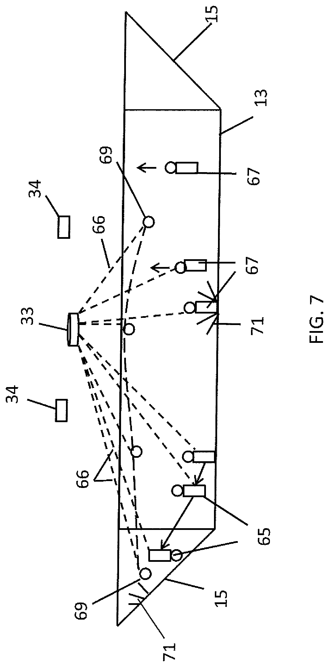
[0020] FIG. 7 is a side view of the arena of FIG. 6, showing tracking of the object and the player.
[0021] FIGS. 8A and 8B are flowcharts illustrating a sample game played in the arena.
DESCRIPTION OF THE PREFERRED EMBODIMENT
[0022] The arena 11 has moveable surfaces in the form of trampolines. Players can walk, run, jump, flip, etc. on these moveable surfaces. The arena also has projectors that project images onto the moveable surfaces, fixed surfaces, and play objects, and speakers for producing sound. The arena also has detection capability for detecting the location and movement of the players and the playing objects (such as balls).
[0023] During a game, or play time, a play environment is projected onto the moveable surfaces, the fixed surfaces and play objects. Players use the play objects to interact with one another and with the projected images. In response to the player's actions, the projected images change. The players are thus immersed in an environment that moves and reacts to the actions of the players. Such reaction includes images changing and moving, as well as production of associated sounds.
[0024] The arena 11 will be described first, followed by a description of the projection and detection system. An example game will then be described.
[0025] In general, the arena 11 (see FIGS. 1 and 2) is located indoors under a roof. The arena can be located in a building that has air conditioning and heat. Alternatively, the building can be open to the outside. This alternative arrangement may be used in locations with mild weather.
[0026] The arena has a floor 13, end walls 15 and side walls 17. The floor 13 is horizontal. The side walls 17 and end walls 15 are angled to the floor, generally at an angle that is not vertical. For example, the end walls maybe angled at about 45 degrees to the floor. The rear side wall 17R may be angled the same or at some other angle, such as 60 degrees. The front side wall 17F may be vertical if not part of the playing area.
[0027] The arena has moveable surfaces for the floor 13, the end walls 15 and some sides. In the preferred embodiment, the moveable surfaces are trampolines. Trampolines are conventional and commercially available. Much of the floor is trampolines 19. Each trampoline is an elastic and flexible material supported by springs. The springs are along the sides of the material. A support structure, in the form of beams, is between the trampolines and serves to anchor the springs. The support structure and springs are covered by padding 21, which padding forms part of the floor. Thus, the floor trampolines are separated from adjacent trampolines by the padding. The trampolines and padding provide surfaces that move when stepped upon by a user.
[0028] The end walls 15 have sloped trampolines 19E (see also FIG. 7). Padding 21 is located between the end trampolines and along the top of the end trampolines. In the preferred embodiment, each floor trampoline 19 merges with an end trampoline 19E. This makes a floor trampoline and the respective end trampoline one trampoline. A vertical wall, such as netting, extends up from the top of each end trampoline to further enclose the arena.
[0029] In the embodiment shown, other side walls 17R, 17F do not have trampolines. However, side wall trampolines can be provided. The rear side wall 17R is padding from the floor up to a predetermine distance. The upper portion of the rear wall is a vertical wall. The front side wall 17F has an opening (not shown) which serves as an entrance and exit for players. The front side wall can be made of padding, or some other material to allow image projection thereon. If no images are projected on the front wall, it may be made of netting to allow spectators on the outside to look in. The front side wall can be a combination of padding and netting, with padding extending a few feet from the floor.
[0030] As shown in FIGS. 1 and 2, the arena is configured for dodgeball and similar type games or activities. There is a centerline 23 that divides the arena floor into two sides. A neutral zone 25 of padding is on both sides of the center line. The door opening is typically located at or near the centerline. The arena has two sides, which are areas on either side of the neutral zone, or centerline. The rules of a particular game may require players on a team to stay confined to their respective sides of the arena.
[0031] The arena can be varied. For example, the number of trampolines on a side can be changed.
[0032] The floor, end and side walls, and especially the padding, is made of a material that provides for the projection of images thereon. Such material may be gray in color.
[0033] Referring to FIG. 2, the projection and detection system 27 is shown. The projection and detection system includes projectors 29. There are floor projectors 29F, end wall projectors 29E, rear side wall projectors 29R and front side wall projectors 29S. Because the areas of the walls and floor are large, there may be more than one projector for each wall or surface. In the embodiment shown, there are four floor projectors, two end wall projectors and two rear wall projectors. In addition, there are two optional front wall projectors to project images onto the front wall. There is also a set of speakers 31. The system also has detection sensors 33 and cameras 34. One or more computers 35 are provided. The computer receives information from the sensors and cameras, and controls the projectors and the speakers. The computer had preprogrammed shows to provide to the projectors and the speakers. However, the shows, images, are subject to change during a game based on player events. An RFID scanner 37 is provided, which is located at the entrance to the arena.
[0034] The projectors 29 use digital image information and project images on large areas. The projectors are located above the arena, typically in the ceiling (see FIG. 3 for example). The ceiling has struts or beams for supporting the roof of the building. The projectors are mounted either directly to the struts, or on structure that spans between struts. The projectors are located so as to project images down into the arena onto the respective surface or surfaces.
[0035] Each end wall projector 29E is located so as to project an image 41 onto the respective end wall 15 (see FIGS. 3 and 4). The rear side wall projectors 29R are also located above the arena, so as to project an image onto the rear wall 17R (see FIG. 4). One rear side wall projector 29R projects onto half of the rear side wall, while the other rear side wall projector projects onto the other half of the rear side wall. The adjacent edges of the two rear side wall images may overlap 43 slightly. The rear side wall may include an angled triangular section 45 that merges with the adjacent angled end wall. In the embodiment shown, the end wall projector projects an image onto this wall section 45. Likewise, the front side wall projectors 29S each project onto half of the front side wall. The floor projectors 29F are also located above the arena and are positioned so as to each project onto a different quadrant of the floor (see FIGS. 3 and 5). The edges of the images may overlap 43.
[0036] The projectors 29 are conventional and commercially available. The projectors 29 are of the large display type. While the projectors themselves are small in size, they are able to project an image onto a large area. The projectors also have a high brightness characteristic, capable of projecting, for example, 8500-12000 lumens. The projectors have the capability of geometric adjustment of the projected image onto the projection surface. For example, a projector may not be aligned normal or perpendicularly to the respective projection surface. Instead, the projector may project an image at an angle to the projection surface. The projection surface may be uneven and nonflat, such as the rear wall and angled corners. The projector can adjust, or map, the image so it does not appear distorted when viewed on the projection surface. In addition, the projectors can stitch adjacent images together with edge blending. For example, one image projected onto the rear wall will have two adjacent side images. One adjacent side image will be projected onto the rear wall. The two rear wall images have overlapping edges. The images at the overlapping edges are blended to provide a seamless edge. The images are all coordinated. Thus, if a projection of a ball is moving along the rear wall, it may move across one rear wall image and then onto the next rear wall image. It may also move onto an adjacent floor image.
[0037] The projectors can map a large image onto the projection surfaces. For example, the walls can be a projection of a color background with stars on the background. The stars can be static or moving. A star can suddenly grow in size and move at a faster speed than before so as to draw the attention of players.
[0038] In addition to projecting visual images, sounds are projected or produced. Speakers 31 are provided for sounds. The speakers are located around the arena, in the ceiling. The sound can be directional, with the speakers on one side playing different sounds than the speakers on the other side.
[0039] The detection sensors detect the players and objects, such as balls, which may be in play. There are one or more LIDAR units 33 and one or more cameras 34. The LIDAR units 33 (light imaging, detection and ranging) are conventional and commercially available. The units are located above the arena so as to have an unobstructed view of the interior. The LIDAR units are located around the perimeter of the arena. The number and location can vary depending on desired resolution. In the embodiment shown, there is a LIDAR unit 33 in each corner, as well as at least one LIDAR unit along each wall.
[0040] The LIDAR unit 33 has plural lasers, which are LEDs (light emitting diodes). The lasers are arranged to point in different direction from one another so as to cover a large space. In addition, each laser scans an area. Each laser is paired with a receiver. When a laser is fired, the paired receiver captures any reflected laser light from an object. Time of flight (TOF) is used to determine distance of the reflective object from the unit. The specific laser and the scan angle of the laser are used to determine the radial direction of the reflective object. In this manner, the location of the reflective object can be determined. In addition, movement of the reflective object can be tracked. Plural LIDAR units can track the object, with the computer 35 combining their data to triangulate and determine the location of the object in three-dimensional space inside the arena. As the object moves from a first position to a second position in the arena, the LIDAR units and computer locates the object at each position.
[0041] While the LIDAR units 33 provide tracking capabilities of objects, the cameras 34 provide additional capabilities. The cameras 34 are body motion, or skeleton, tracking cameras, which are conventional and commercially available. The cameras 34 have software that allows the sensing and detection of a person, or other object, against a background. In addition, sensing of the person in three dimensions is provided. This is sometimes referred to as depth imaging and allows the locating in space of points on a person, or location in space of points on an object. Early applications of body motion required markers worn by a person. The markers allowed the camera to more easily identify points on the person. For example, the person moves arms and legs. The camera detects this movement and an image of the person is displayed on a monitor to provide visual feedback. The software provides recognition capabilities in rendering a so-called skeleton of the person. This skeleton is a stick frame overlaid on the person on the monitor. The skeleton represents a model of the person in motion. The skeleton moves with the person. Markerless versions evolved from fitness routines, where a person stands in front of a camera and moves in a physical exercise routine. One such camera is the Microsoft Kinect.TM. camera. The cameras 34 do not require players to wear markers.
[0042] As a matter of convenience and to provide full coverage of the arena, in the preferred embodiment, a camera 34 is located near each projector. Each camera 34 is pointed so as to view a predetermined space of the arena. For example, the cameras located by the end wall projectors view the space in front of the end walls.
[0043] An example game will be described. Referring to FIGS. 8A and 8B, the arena has an attendant who assists players in the game. Before the game begins and the players enter the arena, the attendant initiates a new game, step 45. The attendant may need to prepare the arena for the new game, such as, for example, positioning the playing objects, which are spherical balls. The balls can be the same type balls used in dodgeball, or something different. The balls are arranged in the neutral zone by the attendant. The attendant signals the computer that a new game should be initiated by pressing a start button on a user interface, such as a tablet computer. The tablet computer (not shown) can connect to the computer 35 by a wireless connection.
[0044] The computer has the LIDAR unit 33 and the cameras 34 scan and locate the balls, step 47. Laser beams from the LIDAR units look inside the arena for the balls. The computer may have the LIDAR units look at the neutral zone first. The cameras 34 also view the arena. Once the computer determines the arena is ready, the players may be admitted. The attendant scans the players at the entrance, step 49. The players wear an rfid device, which is registered to the specific player. The RFID scanner 37 scans this device. During the entry of the players, a pregame show is displayed, step 51. The pregame show involves the projectors 29 displaying images around the arena. For example, if the game involves animated characters, these characters are displayed. The projected characters may appear to move about the arena floor, end walls, rear side wall and front side wall. Other images may include objects, such as balls or blobs. As the projected objects move, streaks, stars, trails, etc., may be projected behind the moving projections. The computer coordinates the projectors to stitch the projected images together into a seamless image or series of images. A character, or other projection, can move across the arena. For example, the character can move around all quadrants of the floor, as well as the end and side walls. Sound in the form of music, speech, etc., is broadcast by the speakers. The sound is coordinated and synced with the images.
[0045] The players are assigned a team, step 53, and move to take their positions on the respective side. The players can jump on the trampolines, reaching heights, doing flips and stunts. The players can jump from one trampoline to another, or from the floor to the end wall and vice versa. As they move into the arena, the LIDAR units 33 and cameras 34 track their movement, step 55. The LIDAR units and cameras track the players' locations throughout the game.
[0046] Once all of the players have entered the arena, starting conditions are displayed, step 57. For example, the rules of the game can be provided by a voice speaking the rules through the speakers and the written rules projected on the walls or floor for viewing. Also, other conditions may be provided. For example, lava images may be displayed in the neutral zone if players are prohibited from entering this area, to emphasize the prohibition.
[0047] The game is initiated by the attendant pressing a start button on the tablet. Game conditions are projected, step 59. The lava is removed allowing players to enter the neutral zone to retrieve balls. After a period of time, or after all of the balls have been retrieved from the neutral zone by players, the lava will be projected again onto the neutral zone. Also, targets are displayed. The players aim for the targets with the balls. Incentives, such as points, can be provided to players who hit the target areas. Targets can be characters, such as a bird, a pig, etc. Some targets can be non-moving, while other targets can move.
[0048] Rules can vary according to the specific game being played. As an example of one game, players throw balls across the centerline attempting to hit a target and/or an opposing player on the other side of the centerline. The computer uses the data from the LIDAR units 33 and cameras 34 to track the location of each player and each ball, step 61. The data from the LIDAR units can be used to refine the location information obtained from the cameras. The computer 35 determines if a ball strikes or hits a target, step 63. If this occurs, struck target conditions are displayed. For example, if the target is a bird, the image may show a burst of feathers as the bird disappears from view. Sound announces the hit target. The sound may be directional or local. For example, if the hit target is on an end wall, the speakers nearby may sound the hit, but not the speakers elsewhere. Players on that side, who may have their backs to the target, can thus hear the result, even if they can't see it. Also, the player may be awarded points, which are accounted for by the computer and provided on a scoreboard. The scoreboard can be projected onto a portion of the rear side wall. The score is changed accordingly. Scores can be kept on a team basis and/or on an individual player basis.
[0049] The striking of a target is illustrated in FIGS. 6 and 7. The terms "right" and "left" sides will be used with reference to the orientation shown in the drawings. In this example, the left side player 65 is moving toward the respective end wall 15, jumping on the trampolines. The computer 35 uses data from the LIDAR units 33 and cameras 34 to track the movement of the player 65. Dashed lines are used to show the invisible laser beams 66 hitting the player and being reflected back to the unit 33 (for simplicity in illustration, in FIGS. 6 and 7 only one LIDAR unit 33 is shown with laser beams 66). The cameras 34 also view and provide data to allow the computer to track. The right side player 67 throws a ball 69 across the arena. The right side player must concentrate on the throw, as images and animations are moving about the surfaces of the arena. For example, birds may be flying about, projected balls could move. In addition, the throwing player typically throws from a trampoline, and may even jump in the air to throw. This adds to the level of difficulty and enjoyment of play.
[0050] The LIDAR unit 33 tracks the movement of the ball 69 and the respective cameras view the ball moving. (FIG. 7 uses an elongated dashed line to show the trajectory of the thrown ball.) The ball crosses the centerline, passes over the floor of the left side and moves toward the end wall. The left side player 65 avoids the incoming ball by using an end wall trampoline to perform a flip. The ball misses the left side player, but hits a target 71. The target 71 is projected onto the end wall by a projector. The computer uses the data from the LIDAR units 33 and cameras 34 to detect the ball hitting the target 71. The computer has the respective end wall projector, the same projector projecting the target, display visual confirmation to the players that the target has been hit. In the example, this is an image of feathers bursting (illustrated schematically by radiating lines).
[0051] Referring back to FIG. 8B, the computer uses the data from the LIDAR units 33 and cameras 34 to detect if a player exceeds a boundary, step 73. The computer correlates the position of the boundary with the position of the player. If so, the computer has the respective projector display a resulting image. For example, as shown in FIG. 6, if a right side player 67 enters the neutral zone 25, a flashing image 71 appears on the floor, sound is generated and a penalty is assigned to the player. A penalty can be a loss of points for the player and/or the player's team. The flashing image is projected by a floor projector 29F.
[0052] From time to time, a player can interact directly with an image. For example, as show in FIG. 6, an image 76 (shown as a triangle) pops up on the rear side wall 17R. The image pops up by suddenly becoming displayed on the wall. A player on that side can contact the surface of the wall underlying the image. This contact is detected by the computer using the data from the LIDAR units and cameras, step 75. The computer correlates the position of the projected image with the position of the player. Points can be awarded to the player and/or the player's team. Conversely, a moving image can "hit" a player, with a penalty assessed for the slow moving player. After contact, the image changes. For example, the image could burst into parts. Or extensions could grow, with the players trying to grow the extensions as long as possible.
[0053] After a predetermined period of time has elapsed, the game ends. A closing show is projected, results tallied and projected, step 77. The players exit the arena.
[0054] The arena thus allows players to move about on movable surfaces such as trampolines. The trampolines add to the freedom of movement for each player, as well as introduce some difficulty for inexperienced players. The images, and associated sound, provide an active dynamic environment for the players to play is, as the images around the players, on the floor and the walls, are changing. In addition, the images change in reaction to the players. Players can interact by contacting the image indirectly, such as throwing a ball, or directly. The interaction can lead to rewards for the players, or it can lead to penalties.
[0055] Because the images are projected and are not painted or otherwise fixed to the surfaces, the arena can host a variety of games. Different games would use different images and sounds.
[0056] Various games can be played in the arena. For example, a teamless version can be played, where each player plays against all the other players. Each player tries to hit the other players and the images projected on the arena surfaces. Such a teamless game is enjoyable when only a few players are in the arena.
[0057] The foregoing disclosure and showings made in the drawings are merely illustrative of the principles of this invention and are not to be interpreted in a limiting sense.
* * * * *
D00000
D00001
D00002
D00003
D00004
D00005
D00006
D00007
D00008
D00009
XML
uspto.report is an independent third-party trademark research tool that is not affiliated, endorsed, or sponsored by the United States Patent and Trademark Office (USPTO) or any other governmental organization. The information provided by uspto.report is based on publicly available data at the time of writing and is intended for informational purposes only.
While we strive to provide accurate and up-to-date information, we do not guarantee the accuracy, completeness, reliability, or suitability of the information displayed on this site. The use of this site is at your own risk. Any reliance you place on such information is therefore strictly at your own risk.
All official trademark data, including owner information, should be verified by visiting the official USPTO website at www.uspto.gov. This site is not intended to replace professional legal advice and should not be used as a substitute for consulting with a legal professional who is knowledgeable about trademark law.