Delivery Systems And Methods For Left Ventricular Pacing
Grenz; Nathan A. ; et al.
U.S. patent application number 16/723805 was filed with the patent office on 2020-06-25 for delivery systems and methods for left ventricular pacing. The applicant listed for this patent is Medtronic, Inc.. Invention is credited to Ronald A. Drake, Nathan A. Grenz, Douglas S. Hine, Zhongping Yang.
| Application Number | 20200197706 16/723805 |
| Document ID | / |
| Family ID | 69187965 |
| Filed Date | 2020-06-25 |


View All Diagrams
| United States Patent Application | 20200197706 |
| Kind Code | A1 |
| Grenz; Nathan A. ; et al. | June 25, 2020 |
DELIVERY SYSTEMS AND METHODS FOR LEFT VENTRICULAR PACING
Abstract
A method of delivering a pacing lead may include locating a potential implantation site adjacent to or within the triangle of Koch region of a patient's heart. The method may include advancing a pacing lead to the potential implantation site. The pacing lead has an elongate body and a fixation element coupled to a distal portion and attachable to the right-atrial endocardium adjacent to or within the triangle of Koch region. The method may include implanting the pacing lead at the potential implantation site to or sense electrical activity of the left ventricle in the basal and/or septal region of the left ventricular myocardium of the patient's heart. The pacing lead may include a lumen configured to receive a guide wire. A sheath of a delivery system used to deliver the pacing lead may include two or more curves to facilitate implanting the pacing lead at the implantation site.
| Inventors: | Grenz; Nathan A.; (North Oaks, MN) ; Drake; Ronald A.; (St. Louis Park, MN) ; Yang; Zhongping; (Woodbury, MN) ; Hine; Douglas S.; (Forest Lake, MN) | ||||||||||
| Applicant: |
|
||||||||||
|---|---|---|---|---|---|---|---|---|---|---|---|
| Family ID: | 69187965 | ||||||||||
| Appl. No.: | 16/723805 | ||||||||||
| Filed: | December 20, 2019 |
Related U.S. Patent Documents
| Application Number | Filing Date | Patent Number | ||
|---|---|---|---|---|
| 62783479 | Dec 21, 2018 | |||
| Current U.S. Class: | 1/1 |
| Current CPC Class: | A61N 1/37512 20170801; A61N 1/3682 20130101; A61B 5/04085 20130101; A61B 5/042 20130101; A61B 5/1107 20130101; A61B 7/023 20130101; A61B 7/04 20130101; A61B 5/061 20130101; A61N 2001/0585 20130101; A61B 5/4836 20130101; A61B 2562/0204 20130101; A61N 1/3684 20130101; A61B 5/0031 20130101; A61B 5/0538 20130101; A61B 5/6805 20130101; A61N 1/0573 20130101; A61N 1/37518 20170801; A61N 1/3756 20130101; A61N 1/056 20130101; A61N 1/3627 20130101; A61N 2001/0578 20130101 |
| International Class: | A61N 1/368 20060101 A61N001/368; A61N 1/05 20060101 A61N001/05 |
Claims
1. A method of delivering a pacing lead comprising: locating a potential implantation site adjacent to or within the triangle of Koch region in the right atrium of a patient's heart; advancing a pacing lead to the potential implantation site, the pacing lead comprising an elongate body extending from a proximal portion to a distal portion and a fixation element coupled to the distal portion and attachable to the right-atrial endocardium adjacent to or within the triangle of Koch region in the right atrium of the patient's heart; and implanting the pacing lead at the potential implantation site to deliver cardiac therapy to and sense electrical activity of the left ventricle in the basal region, septal region, or basal-septal region of the left ventricular myocardium of the patient's heart.
2. The method according to claim 1, further comprising implanting a left-ventricular electrode coupled to the distal portion of the pacing lead from tissue adjacent to or within the triangle of Koch region of the right atrium through the right-atrial endocardium and optionally the central fibrous body to deliver cardiac therapy to and sense electrical activity of the left ventricle in the basal region, septal region, or basal-septal region of the left ventricular myocardium of the patient's heart.
3. The method according to claim 1, further comprising positioning an atrial electrode of the pacing lead adjacent to or proximal to the fixation element to deliver cardiac therapy to or sense electrical activity of the atrium of the patient's heart.
4. The method according to claim 1, wherein locating the potential implantation site comprises: optionally inserting a guide wire into a lumen of a sheath; advancing the guide wire and the sheath into the coronary sinus of the patient's heart; advancing a needle-tipped dilator over the guide wire and through the lumen of the sheath to the coronary sinus; engaging tissue in the potential implantation site adjacent to or within the triangle of Koch region in the right atrium of the patient's heart with the needle-tipped dilator; testing the potential implantation site adjacent to or within the triangle of Koch region in the right atrium of the patient's heart using the needle-tipped dilator; and determining whether the potential implantation site is acceptable based on the testing using the needle-tipped dilator.
5. The method according to claim 4, further comprising: withdrawing the needle-tipped dilator from tissue in the potential implantation site in response to determining that the potential implantation site is not acceptable; and optionally locating a new potential implantation site adjacent to or within the triangle of Koch region in the right atrium of the patient's heart.
6. The method according to claim 4, further comprising forming an opening in tissue in the potential implantation site using the needle-tipped dilator in response to determining that the potential implantation site is acceptable.
7. The method according to claim 1, further comprising preparing the potential implantation site for the pacing lead based on a size of a guide wire.
8. The method according to claim 7, wherein preparing the potential implantation site for the pacing lead comprises: advancing the guide wire to the potential implantation site; advancing a sheath over the guide wire and into an opening in tissue in the potential implantation site formed by a needle-tipped dilator; and withdrawing the needle-tipped dilator and the guide wire through a lumen of the sheath, wherein the pacing lead is advanced to the potential implantation site while the pacing lead is at least partially disposed in the lumen of the sheath.
9. The method according to claim 7, wherein preparing the potential implantation site for the pacing lead comprises: advancing the guide wire into an opening in tissue in the potential implantation site formed by a needle-tipped dilator; withdrawing the needle-tipped dilator over the guide wire; and exchanging the needle-tipped dilator with the pacing lead, wherein the pacing lead is advanced to the potential implantation site over the guide wire.
10. The method according to claim 4, wherein the needle-tipped dilator comprises a dilator portion and a needle portion separable from the dilator portion.
11. The method according to claim 1, further comprising: testing the potential implantation site using the pacing lead; determining whether the potential implantation site is acceptable based on the testing using the pacing lead; and fixing the pacing lead in the potential implantation site in response to determining that the potential implantation site is acceptable based on the testing using the pacing lead.
12. A pacing lead delivery system comprising: a sheath comprising an elongate body defining a lumen extending between a proximal portion and a distal portion; a guide wire at least partially disposable in the lumen of the sheath; a needle-tipped dilator configured to advance over the guide wire and to engage tissue in a potential implantation site; and a pacing lead comprising an elongate body extending from a proximal portion to a distal portion and a fixation element coupled to the distal portion and attachable to an implantation site in the right-atrial endocardium adjacent to or within the triangle of Koch region in the right atrium of a patient's heart to deliver cardiac therapy to and sense electrical activity of the left ventricle in the basal region, septal region, or basal-septal region of the left ventricular myocardium of the patient's heart.
13. The pacing lead delivery system according to claim 12, wherein the elongate body defines a lumen extending between the proximal portion and the distal portion configured to receive the guide wire.
14. The pacing lead delivery system according to claim 12, wherein the fixation element of the pacing lead comprises a helical attachment element.
15. The pacing lead delivery system according to claim 14, wherein the pacing lead is freely rotatable relative to the sheath, the guide wire, or both.
16. The pacing lead delivery system according to claim 12, wherein the sheath comprises a fixed curve configured to extend to the implantation site adjacent to or within the triangle of Koch region in the right atrium of the patient's heart using the coronary sinus.
17. The pacing lead delivery system according to claim 12, wherein the sheath is deflectable and comprises a first curve segment and a second curve segment distal to the first curve segment configured to extend to the implantation site adjacent to or within the triangle of Koch region in the right atrium of the patient's heart through the coronary sinus.
18. The pacing lead delivery system according to claim 17, wherein the first curve segment has a first radius of curvature and the second curve segment has a second radius of curvature less than the first radius of curvature.
19. The pacing lead delivery system according to claim 17, wherein the first curve segment is aligned to a first plane and the second curve segment is aligned to a second plane having a different orientation than the first plane.
20. The pacing lead delivery system according to claim 17, wherein the first curve segment is adjustable relative to the second curve segment.
21. The pacing lead delivery system according to claim 12, wherein the needle-tipped dilator or guide wire is configured to form an opening in tissue in the potential implantation site.
22. The pacing lead delivery system according to claim 21, wherein the sheath is configured to be inserted into the opening in tissue formed by the needle-tipped dilator to guide the pacing lead to the potential implantation site.
23. The pacing lead delivery system according to claim 21, wherein the guide wire is configured to be inserted into the opening in tissue formed by the needle-tipped dilator to guide advancement of the pacing lead to the potential implantation site.
24. A pacing lead delivery system comprising: a sheath comprising an elongate body defining a lumen extending between a proximal portion and a distal portion; a guide wire at least partially disposable in the lumen of the sheath and configured to engage tissue in a potential implantation site; and a pacing lead comprising an elongate body extending from a proximal portion to a distal portion and a fixation element coupled to the distal portion and attachable to an implantation site in the right-atrial endocardium adjacent to or within the triangle of Koch region in the right atrium of a patient's heart to and sense electrical activity of the left ventricle in the basal region, septal region, or basal-septal region of the left ventricular myocardium of the patient's heart.
25. The pacing lead delivery system of claim 24, wherein the elongate body defines a lumen extending between the proximal portion and the distal portion configured to receive the guide wire.
Description
[0001] The present application claims the benefit of U.S. Provisional Application Ser. No. 62/783,479, filed Dec. 21, 2018, which is incorporated by reference in its entirety.
[0002] The present technology is generally related to medical device methods and systems, such as methods and systems for implantable medical device implantation and use.
[0003] The cardiac conduction system includes the sinus atrial (SA) node, the atrioventricular (AV) node, the bundle of His, bundle branches and Purkinje fibers. A heartbeat is initiated in the SA node, which may be described as the natural "pacemaker" of the heart. An electrical impulse arising from the SA node causes the atrial myocardium to contract. The electrical impulse, or electrical pulse or signal, is conducted to the ventricles via the AV node which inherently delays the conduction to allow the atria to stop contracting before the ventricles begin contracting thereby providing proper AV synchrony. The electrical impulse is conducted from the AV node to the ventricular myocardium via the bundle of His, bundle branches, and Purkinje fibers.
[0004] Patients with a conduction system abnormality, such as poor AV node conduction or poor SA node function, may receive an implantable medical device (IMD), such as a pacemaker, to restore a more normal heart rhythm and AV synchrony. Some types of IMDs, such as cardiac pacemakers, implantable cardioverter defibrillators (ICDs), or cardiac resynchronization therapy (CRT) devices, provide therapeutic electrical stimulation to a heart of a patient via electrodes on one or more implantable endocardial, epicardial, or coronary venous leads that are positioned in or adjacent to the heart. The therapeutic electrical stimulation may be delivered to the heart in the form of pulses or shocks for pacing, cardioversion, or defibrillation. In some cases, an IMD may sense intrinsic depolarizations of the heart, and control the delivery of therapeutic stimulation to the heart based on the sensing.
[0005] Delivery of therapeutic electrical stimulation to the heart can be useful in addressing cardiac conditions such as ventricular dyssynchrony that may occur in patients. Ventricular dyssynchrony may be described as a lack of synchrony or a difference in the timing of contractions in the right and left ventricles of the heart. Significant differences in the timing of contractions can reduce cardiac efficiency. CRT, delivered by an IMD to the heart, may enhance cardiac output by resynchronizing the electromechanical activity of the ventricles of the heart. CRT may include "triple-chamber pacing" when pacing the right atrium, right ventricle, and left ventricle.
[0006] Cardiac arrhythmias may be treated by delivering electrical shock therapy for cardioverting or defibrillating the heart in addition to cardiac pacing, for example, from an ICD, which may sense a patient's heart rhythm and classify the rhythm according to an arrhythmia detection scheme in order to detect episodes of tachycardia or fibrillation. Arrhythmias detected may include ventricular tachycardia (VT), fast ventricular tachycardia (FVT), ventricular fibrillation (VF), atrial tachycardia (AT) and atrial fibrillation (AT). Anti-tachycardia pacing (ATP) can be used to treat ventricular tachycardia (VT) to terminate substantially many monomorphic fast rhythms.
[0007] Dual chamber medical devices are available that include a transvenous atrial lead carrying electrodes that may be placed in the right atrium and a transvenous ventricular lead carrying electrodes that may be placed in the right ventricle via the right atrium. The dual chamber medical device itself is generally implanted in a subcutaneous pocket, and the transvenous leads are tunneled to the subcutaneous pocket. A dual chamber medical device may sense atrial electrical signals and ventricular electrical signals and can provide both atrial pacing and ventricular pacing as needed to promote a normal heart rhythm and AV synchrony. Some dual chamber medical devices can treat both atrial and ventricular arrhythmias.
[0008] Intracardiac medical devices, such as a leadless pacemaker, have been introduced or proposed for implantation entirely within a patient's heart, eliminating the need for transvenous leads. A leadless pacemaker may include one or more electrodes on its outer housing to deliver therapeutic electrical signals and/or sense intrinsic depolarizations of the heart. Intracardiac medical devices may provide cardiac therapy functionality, such as sensing and pacing, within a single-chamber of the patient's heart. Single-chamber intracardiac devices may also treat either atrial or ventricular arrhythmias or fibrillation. Some leadless pacemakers are not intracardiac and may be positioned outside of the heart and, in some examples, may be anchored to a wall of the heart via a fixation mechanism.
[0009] In some patients, single-chamber devices may adequately address the patient's needs. In other patients, single-chamber sensing and therapy may not fully address cardiac conduction disease or abnormalities in all patients, for example, those with some forms of AV dyssynchrony or tachycardia. Dual chamber sensing and/or pacing functions, in addition to ICD functionality in some cases, may be used to restore more normal heart rhythms.
SUMMARY
[0010] The techniques of this disclosure generally relate to methods and systems for delivering an implantable medical device for left ventricular pacing, for example, to an implantation site adjacent to or within the triangle of Koch region of a patient's heart. In some embodiments, the implantation site may be accessed using the coronary sinus system of the patient's heart. A delivery system may include a sheath having two or more curves to facilitate delivering a pacing lead to an implantation site. The pacing lead may include a lumen, which may be appropriately sized to receive a guidewire. The pacing lead may also include a fixation element to attach to cardiac tissue. In particular, the pacing lead may be configured to attach to an implantation site in the right-atrial endocardium adjacent to or within the triangle of Koch region in the right atrium of the patient's heart.
[0011] In one aspect, the present disclosure provides a method of delivering a pacing lead including: locating a potential implantation site adjacent to or within the triangle of Koch region in the right atrium of a patient's heart. The method also includes advancing a pacing lead to the potential implantation site. The pacing lead includes an elongate body extending from a proximal portion to a distal portion and a fixation element coupled to the distal portion and attachable to the right-atrial endocardium adjacent to or within the triangle of Koch region in the right atrium of the patient's heart. The method also includes implanting the pacing lead at the potential implantation site to deliver cardiac therapy to or sense electrical activity of the left ventricle in the basal region, septal region, or basal-septal region of the left ventricular myocardium of the patient's heart.
[0012] In another aspect, the present disclosure provides a pacing lead delivery system including: a sheath having an elongate body defining a lumen extending between a proximal portion and a distal portion; a guide wire at least partially disposable in the lumen of the sheath; a needle-tipped dilator configured to advance over the guide wire and to engage tissue in a potential implantation site; and a pacing lead having an elongate body extending from a proximal portion to a distal portion and a fixation element coupled to the distal portion and attachable to an implantation site in the right-atrial endocardium adjacent to or within the triangle of Koch region in the right atrium of a patient's heart to deliver cardiac therapy to or sense electrical activity of the left ventricle in the basal region, septal region, or basal-septal region of the left ventricular myocardium of the patient's heart.
[0013] In another aspect, the present disclosure provides, a pacing lead including an elongate body defining a lumen extending from a proximal portion to a distal portion configured to receive a guide wire; and a left-ventricular electrode coupled to the elongate body implantable from tissue adjacent to or within the triangle of Koch region of the right atrium through the right-atrial endocardium to deliver cardiac therapy to or sense electrical activity of the left ventricle in the basal region, septal region, or basal-septal region of the left ventricular myocardium of a patient's heart.
[0014] In another aspect, the present disclosure provides a pacing lead delivery system including a sheath having an elongate body defining a lumen extending between a proximal portion and a distal portion; a guide wire at least partially disposable in the lumen of the sheath and configured to engage tissue in a potential implantation site; and a pacing lead having an elongate body extending from a proximal portion to a distal portion and a fixation element coupled to the distal portion and attachable to an implantation site in the right-atrial endocardium adjacent to or within the triangle of Koch region in the right atrium of a patient's heart to or sense electrical activity of the left ventricle in the basal region, septal region, or basal-septal region of the left ventricular myocardium of the patient's heart.
[0015] The details of one or more aspects of the disclosure are set forth in the accompanying drawings and the description below. Other features, objects, and advantages of the techniques described in this disclosure will be apparent from the description and drawings, and from the claims.
BRIEF DESCRIPTION OF THE DRAWINGS
[0016] FIG. 1 is a conceptual diagram of an illustrative cardiac therapy system including an intracardiac medical device implanted in a patient's heart and a separate medical device positioned outside of the patient's heart for use with, e.g., the illustrative methods of FIGS. 29-34.
[0017] FIGS. 2-4 are conceptual diagrams of illustrative cardiac therapy systems including medical devices including leads with electrodes implanted in a patient's heart for use with, e.g., the illustrative methods of FIGS. 29-34.
[0018] FIG. 5 is an enlarged conceptual diagram of the intracardiac medical device of FIG. 1 and anatomical structures of the patient's heart.
[0019] FIG. 6 is a conceptual diagram of a map of a patient's heart in a standard 17 segment view of the left ventricle showing various electrode implantation locations for use with, e.g., the illustrative systems and devices of FIGS. 1-4 and FIGS. 16-28.
[0020] FIG. 7 is a perspective view of an intracardiac medical device having a distal fixation and electrode assembly that includes a distal housing-based electrode implemented as a ring electrode for use with, e.g., the illustrative systems and devices of FIGS. 1-4 and FIGS. 16-28.
[0021] FIG. 8 is a block diagram of illustrative circuitry that may be enclosed within the housing of the medical devices of FIGS. 1-4 and FIGS. 16-28, for example, to provide the functionality and therapy described herein.
[0022] FIG. 9 is a perspective view of another illustrative intracardiac medical device for use with, e.g., the illustrative systems and devices of FIGS. 1-4 and FIGS. 16-28.
[0023] FIG. 10 is a flowchart of an illustrative method of detecting atrial activity using an atrial motion detector for use with, e.g., the illustrative systems and devices of FIGS. 1-4 and FIGS. 16-28.
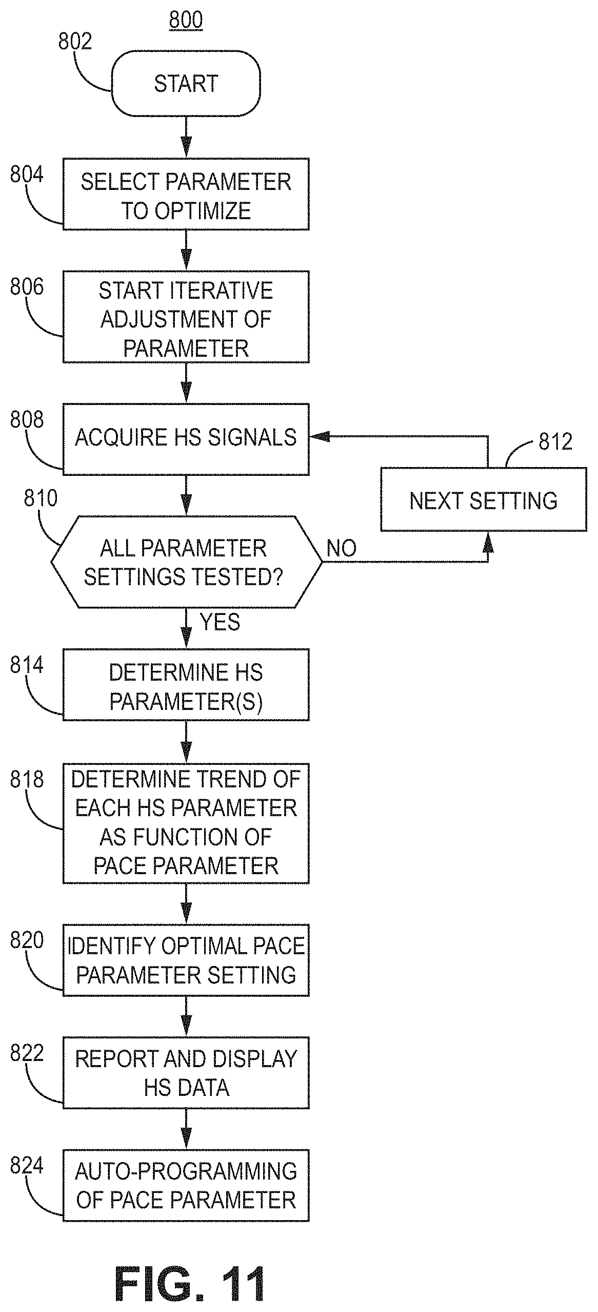
[0024] FIG. 11 is a flowchart of an illustrative method of detecting heart sounds to represent physiological response information for use with, e.g., the illustrative systems and devices of FIGS. 1-4 and FIGS. 16-28.
[0025] FIG. 12 is a flowchart of an illustrative method of detecting bioimpedance to represent physiological response information for use with, e.g., the illustrative systems and devices of FIGS. 1-4 and FIGS. 16-28.
[0026] FIG. 13 is a diagram of an illustrative system including electrode apparatus, display apparatus, and computing apparatus for use with, e.g., the illustrative systems and devices of FIGS. 1-4 and FIGS. 16-28.
[0027] FIGS. 14-15 are diagrams of illustrative external electrode apparatus for measuring torso-surface potentials for use with, e.g., the illustrative systems and devices of FIGS. 1-4 and FIGS. 16-28.
[0028] FIGS. 16-25 are illustrations showing various configurations of a pacing lead delivery system for use with, e.g., the illustrative systems and devices of FIGS. 1-4 and methods of FIGS. 29-34.
[0029] FIG. 26 is an illustration of a right anterior oblique cutaway view of the patient's heart and the illustrative pacing lead delivery system of FIGS. 16-25.
[0030] FIG. 27 is an illustration of an overhead cutaway view the patient's heart and the illustrative pacing lead delivery system of FIGS. 16-25 in the same position as shown in FIG. 26.
[0031] FIG. 28 is an illustration of the patient's heart showing a target implantation zone for use with, e.g., the illustrative systems and devices of FIGS. 1-4 and the illustrative pacing lead delivery system of FIGS. 16-25.
[0032] FIG. 29 is a flow diagram of a method of using, e.g., the illustrative systems and devices of FIGS. 1-4 and the illustrative pacing lead delivery system of FIGS. 16-28.
[0033] FIG. 30 is a flow diagram of one example of a method for locating a potential implantation site for use with, e.g., the illustrative method of FIG. 29.
[0034] FIG. 31 is a flow diagram of a further example of a method for locating a potential implantation site for use with, e.g., the illustrative method of FIG. 29.
[0035] FIG. 32 is a flow diagram of one example of a method for preparing an implantation site for use with, e.g., the illustrative method of FIG. 29.
[0036] FIG. 33 is a flow diagram of another example of a method for preparing an implantation site for use with, e.g., the illustrative method of FIG. 29.
[0037] FIG. 34 is a flow diagram of a further example of a method for preparing an implantation site for use with, e.g., the illustrative method of FIG. 29.
DETAILED DESCRIPTION
[0038] The techniques of this disclosure generally relate to delivering implantable medical devices to provide cardiac therapy using the cardiac conduction system or left ventricular myocardium. In particular, the delivery systems and techniques may be used to implant implantable medical devices through the right atrium to the left ventricle (e.g., ventricle-from-atrium, or VfA) from the triangle of Koch region or the coronary sinus. In some embodiments, various techniques described herein may be applied to His bundle or bundle branch pacing applications that use the cardiac conduction system. Various non-limiting examples of cardiac therapy include single chamber or multiple chamber pacing (e.g., dual or triple chamber pacing), atrioventricular synchronous pacing, asynchronous pacing, triggered pacing, cardiac resynchronization pacing, or tachycardia-related therapy. Although reference is made herein to implantable medical devices, such as a pacemaker or ICD, the methods and processes may be used with any medical devices, systems, or methods related to a patient's heart. Various other applications will become apparent to one of skill in the art having the benefit of the present disclosure.
[0039] It may be beneficial to provide an implantable medical device delivery system and technique to locate an electrode for sensing or pacing the left ventricular myocardium or the cardiac conduction system. It may also be beneficial to provide a delivery system and technique to deliver an implantable medical device adjacent to or within the triangle of Koch region at an appropriate angle for left ventricular pacing, for example, using the endocardium and/or the cardiac conduction system.
[0040] As used herein, the term "capture" generally refers to obtaining information or data, for example, related to imaging. The term "capture" in the context of pacing (e.g., effective capture of the heart from pacing) refers to determining whether a desired response is sensed in response to stimuli, such as sensing desirable electrical activity in response to electrical pulses delivered to a portion of the heart.
[0041] As used herein, the term "effective" generally refers to meeting conditions that would be sufficient to a person of ordinary skill in the art for performing a particular function. For example, effective pacing of the left ventricle may result in capture of the left ventricle when electrical or mechanical activity of the left ventricle is sensed and determined to provide cardiac therapy as desired.
[0042] The present disclosure provides a technique for delivering an implantable medical device for left ventricular pacing, for example, to an implantation site adjacent to or within the triangle of Koch region of a patient's heart. In some embodiments, the implantation site may be accessed using the coronary sinus system of the patient's heart. In particular, the delivery systems and techniques may be used to deliver a pacing lead to an implantation site. Delivery systems may include a sheath having two or more curves to facilitate delivering the pacing lead to an implantation site. The pacing lead may include a lumen, which may be appropriately sized to receive a guidewire. The pacing lead may also include a fixation element to attach to cardiac tissue. In particular, the pacing lead may be configured to attach to an implantation site in the right-atrial endocardium adjacent to or within the triangle of Koch region in the right atrium of the patient's heart.
[0043] In some embodiments, the tissue-piercing electrode may be implanted in the basal region, septal region, or basal-septal region of the left ventricular myocardium of the patient's heart from the triangle of Koch region of the right atrium through the right-atrial endocardium and central fibrous body. In a leadless implantable medical device, the tissue-piercing electrode may leadlessly extend from a distal end region of a housing of the device, and the right-atrial electrode may be leadlessly coupled to the housing (e.g., part of or positioned on the exterior of the housing). The right-atrial motion detector may be within the implantable medical device. In a leaded implantable medical device, one or more of the electrodes may be coupled to the housing using an implantable lead. When the device is implanted, the electrodes may be used to sense electrical activity in one or more atria and/or ventricles of a patient's heart. The motion detector may be used to sense mechanical activity in one or more atria and/or ventricles of the patient's heart. In particular, the activity of the right atrium and the left ventricle may be monitored and, optionally, the activity of the right ventricle may be monitored. The electrodes may be used to deliver cardiac therapy, such as single-chamber pacing for atrial fibrillation, atrioventricular synchronous pacing for bradycardia, asynchronous pacing, triggered pacing, cardiac resynchronization pacing for ventricular dyssynchrony, anti-tachycardia pacing, or shock therapy. Shock therapy may be initiated by the implantable medical device. A separate medical device, such as an extravascular ICD, which may also be implanted, may be in operative communication with the implantable medical device and may deliver an electrical shock in response to a trigger, such as a signaling pulse (e.g., triggering, signaling, or distinctive electrical pulse) provided by the device.
[0044] In general, electrical or mechanical activity may be sensed, determined, acquired, or monitored using various techniques available to one having ordinary skill in the art who has the benefit of the present disclosure. As used herein, the term "monitoring" generally refers to sensing, acquiring, or receiving data or information that may be used, for example, being processed or stored.
[0045] The present disclosure also provides a technique to deliver and implant a medical device, for example, in the triangle of Koch region in the right atrium. Various devices may be used to identify the general location of the triangle of Koch region, which may be described as an implantation site. A flexible lead, or another probe, may be advanced to the potential implantation site and used to identify a precise location for implantation of a medical device, such as an electrode, leadlet, lead, or intracardiac device. In particular, the techniques of the present disclosure may be used to implant a device to provide synchronous pacing to patients with dyssynchrony, as well as provide dual chamber pacing for bradycardia patients with moderate heart failure.
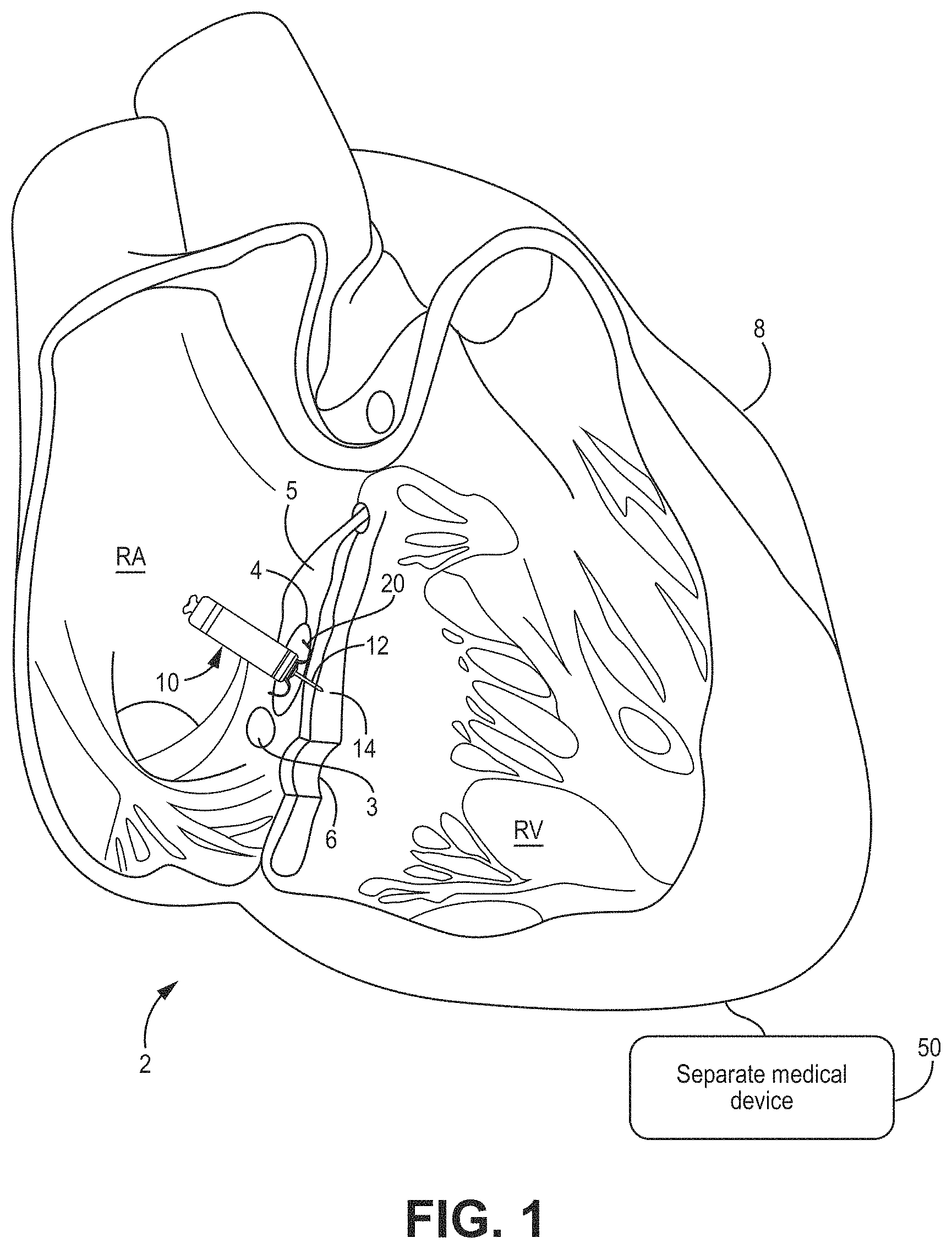
[0046] FIGS. 1-4 show examples of various cardiac therapy systems that may be implanted using, for example, the methods shown in FIGS. 29-34 to deliver a medical device to an implantation site. In these views, the left ventricle (LV) is positioned generally behind the right ventricle (RV).
[0047] Although the present disclosure describes leadless and leaded implantable medical devices, reference is first made to FIG. 1, which shows a conceptual diagram of a cardiac therapy system 2 including an intracardiac medical device 10 that may be configured for single or dual chamber therapy and implanted in a patient's heart 8. In some embodiments, the device 10 may be configured for single-chamber pacing and may, for example, switch between single-chamber and multiple-chamber pacing (e.g., dual- or triple-chamber pacing). As used herein, "intracardiac" refers to a device configured to be implanted entirely within a patient's heart, for example, to provide cardiac therapy. The device 10 is shown implanted in the right atrium (RA) of the patient's heart 8 in a target implant region 4. The device 10 may include one or more fixation members 20 that anchor a distal end of the device against the atrial endocardium in a target implant region 4. The target implant region 4 may lie between the His bundle 5 (or bundle of His) and the coronary sinus 3 and may be adjacent the tricuspid valve 6. The device 10 may be described as a ventricle-from-atrium (VfA) device, which may sense or provide therapy to one or both ventricles (e.g., right ventricle, left ventricle, or both ventricles, depending on the circumstances) while being generally disposed in the right atrium. In particular, the device 10 may include a tissue-piercing electrode that may be implanted in the basal region, septal region, or basal-septal region of the left ventricular myocardium of the patient's heart from the triangle of Koch region of the right atrium through the right-atrial endocardium and central fibrous body.
[0048] The device 10 may be described as a leadless implantable medical device. As used herein, "leadless" refers to a device being free of a lead extending out of the patient's heart 8. In other words, a leadless device may have a lead that does not extend from outside of the patient's heart to the inside of the patient's heart. Some leadless devices may be introduced through a vein, but once implanted, the device is free of, or may not include, any transvenous lead and may be configured to provide cardiac therapy without using any transvenous lead. Further, a leadless VfA device, in particular, does not use a lead to operably connect to an electrode in the ventricle when a housing of the device is positioned in the atrium. Additionally, a leadless electrode may be coupled to the housing of the medical device without using a lead between the electrode and the housing.
[0049] The device 10 may include a dart electrode assembly 12 defining, or having, a straight shaft extending from the distal end region of device 10. The dart electrode assembly 12 may be placed, or at least configured to be placed, through the atrial myocardium and the central fibrous body and into the ventricular myocardium 14, or along the ventricular septum, without perforating entirely through the ventricular endocardial or epicardial surfaces. The dart electrode assembly 12 may carry, or include, an electrode at the distal end region of the shaft such that the electrode may be positioned within the ventricular myocardium for sensing ventricular signals and delivering ventricular pulses (e.g., to depolarize the left ventricle to initiate a contraction of the left ventricle). In some examples, the electrode at the distal end region of the shaft is a cathode electrode provided for use in a bipolar electrode pair for pacing and sensing. While the implant region 4 as illustrated may enable one or more electrodes of the dart electrode assembly 12 to be positioned in the ventricular myocardium, it is recognized that a device having the aspects disclosed herein may be implanted at other locations for multiple chamber pacing (e.g., dual- or triple-chamber pacing), single-chamber pacing with multiple chamber sensing, single-chamber pacing and/or sensing, or other clinical therapy and applications as appropriate.
[0050] It is to be understood that although device 10 is described herein as including a single dart electrode assembly, the device 10 may include more than one dart electrode assembly placed, or configured to be placed, through the atrial myocardium and the central fibrous body, and into the ventricular myocardium 14, or along the ventricular septum, without perforating entirely through the ventricular endocardial or epicardial surfaces. Additionally, each dart electrode assembly may carry, or include, more than a single electrode at the distal end region, or along other regions (e.g., proximal or central regions), of the shaft.
[0051] The cardiac therapy system 2 may also include a separate medical device 50 (depicted diagrammatically in FIG. 1), which may be positioned outside the patient's heart 8 (e.g., subcutaneously) and may be operably coupled to the patient's heart 8 to deliver cardiac therapy thereto. In one example, separate medical device 50 may be an extravascular ICD. In some embodiments, an extravascular ICD may include a defibrillation lead including, or carrying, a defibrillation electrode. A therapy vector may exist between the defibrillation electrode on the defibrillation lead and a housing electrode of the ICD. Further, one or more electrodes of the ICD may also be used for sensing electrical signals related to the patient's heart 8. The ICD may be configured to deliver shock therapy including one or more defibrillation or cardioversion shocks. For example, if an arrhythmia is sensed, the ICD may send a pulse via the electrical lead wires to shock the heart and restore its normal rhythm. In some examples, the ICD may deliver shock therapy without placing electrical lead wires within the heart or attaching electrical wires directly to the heart (subcutaneous ICDs). Examples of extravascular, subcutaneous ICDs that may be used with the system 2 described herein may be described in U.S. Pat. No. 9,278,229 (Reinke et al.), issued 8 Mar. 2016, which is incorporated herein by reference in its entirety.
[0052] In the case of shock therapy (e.g., defibrillation shocks provided by the defibrillation electrode of the defibrillation lead), the separate medical device 50 (e.g., extravascular ICD) may include a control circuit that uses a therapy delivery circuit to generate defibrillation shocks having any of a number of waveform properties, including leading-edge voltage, tilt, delivered energy, pulse phases, and the like. The therapy delivery circuit may, for instance, generate monophasic, biphasic, or multiphasic waveforms. Additionally, the therapy delivery circuit may generate defibrillation waveforms having different amounts of energy. For example, the therapy delivery circuit may generate defibrillation waveforms that deliver a total of between approximately 60-80 Joules (J) of energy for subcutaneous defibrillation.
[0053] The separate medical device 50 may further include a sensing circuit. The sensing circuit may be configured to obtain electrical signals sensed via one or more combinations of electrodes and to process the obtained signals. The components of the sensing circuit may include analog components, digital components, or a combination thereof. The sensing circuit may, for example, include one or more sense amplifiers, filters, rectifiers, threshold detectors, analog-to-digital converters (ADCs), or the like. The sensing circuit may convert the sensed signals to digital form and provide the digital signals to the control circuit for processing and/or analysis. For example, the sensing circuit may amplify signals from sensing electrodes and may convert the amplified signals to multi-bit digital signals by an ADC, and then provide the digital signals to the control circuit. In one or more embodiments, the sensing circuit may also compare processed signals to a threshold to detect the existence of atrial or ventricular depolarizations (e.g., P- or R-waves) and indicate the existence of the atrial depolarization (e.g., P-waves) or ventricular depolarizations (e.g., R-waves) to the control circuit.
[0054] The device 10 and the separate medical device 50 may cooperate to provide cardiac therapy to the patient's heart 8. For example, the device 10 and the separate medical device 50 may be used to detect tachycardia, monitor tachycardia, and/or provide tachycardia-related therapy. For example, the device 10 may communicate with the separate medical device 50 wirelessly to trigger shock therapy using the separate medical device 50. As used herein, "wirelessly" refers to an operative coupling or connection without using a metal conductor between the device 10 and the separate medical device 50. In one example, wireless communication may use a distinctive, signaling, or triggering electrical-pulse provided by the device 10 that conducts through the patient's tissue and is detectable by the separate medical device 50. In another example, wireless communication may use a communication interface (e.g., an antenna) of the device 10 to provide electromagnetic radiation that propagates through patient's tissue and is detectable, for example, using a communication interface (e.g., an antenna) of the separate medical device 50.
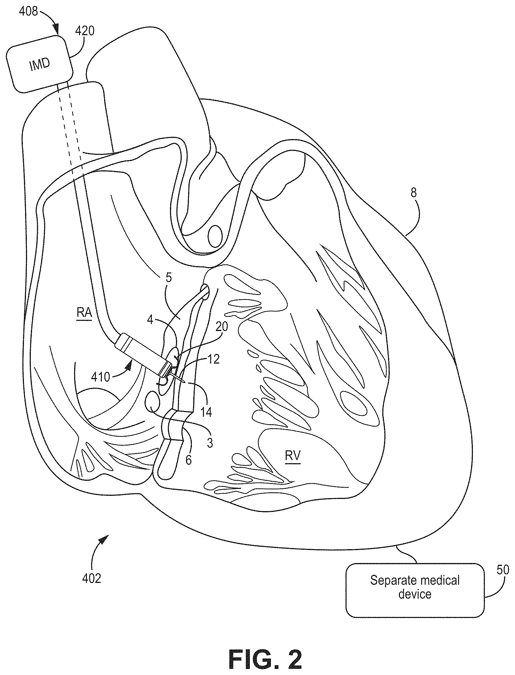
[0055] With reference to FIG. 2, a cardiac therapy system 402 may include a leaded medical device 408 including one, or a single, implantable lead 410 having a tissue-piercing electrode assembly 12 coupled to a distal end region of the lead and implanted inside the patient's heart 8. The housing 420 of the leaded medical device 408 may be implanted and positioned outside of the patient's heart 8 and be configured to calibrate pacing therapy and/or deliver pacing therapy. The lead 410 may include a right-atrial electrode, and the device 408 may operate as a dual-channel capable device (e.g., pacing and/or sensing in both the right atrium and left ventricle). In some embodiments, the lead 410 may not include a right-atrial electrode. In other words, the leaded medical device 408 may be a single channel device, which may be used for asynchronous, triggered, or another type of single-channel pacing. The leaded medical device 408, using the lead 410, may sense activity or deliver pacing to the left ventricle (LV) when the tissue-piercing electrode assembly 12 is implanted, for example, in the same or similar manner as described with respect to FIG. 1.
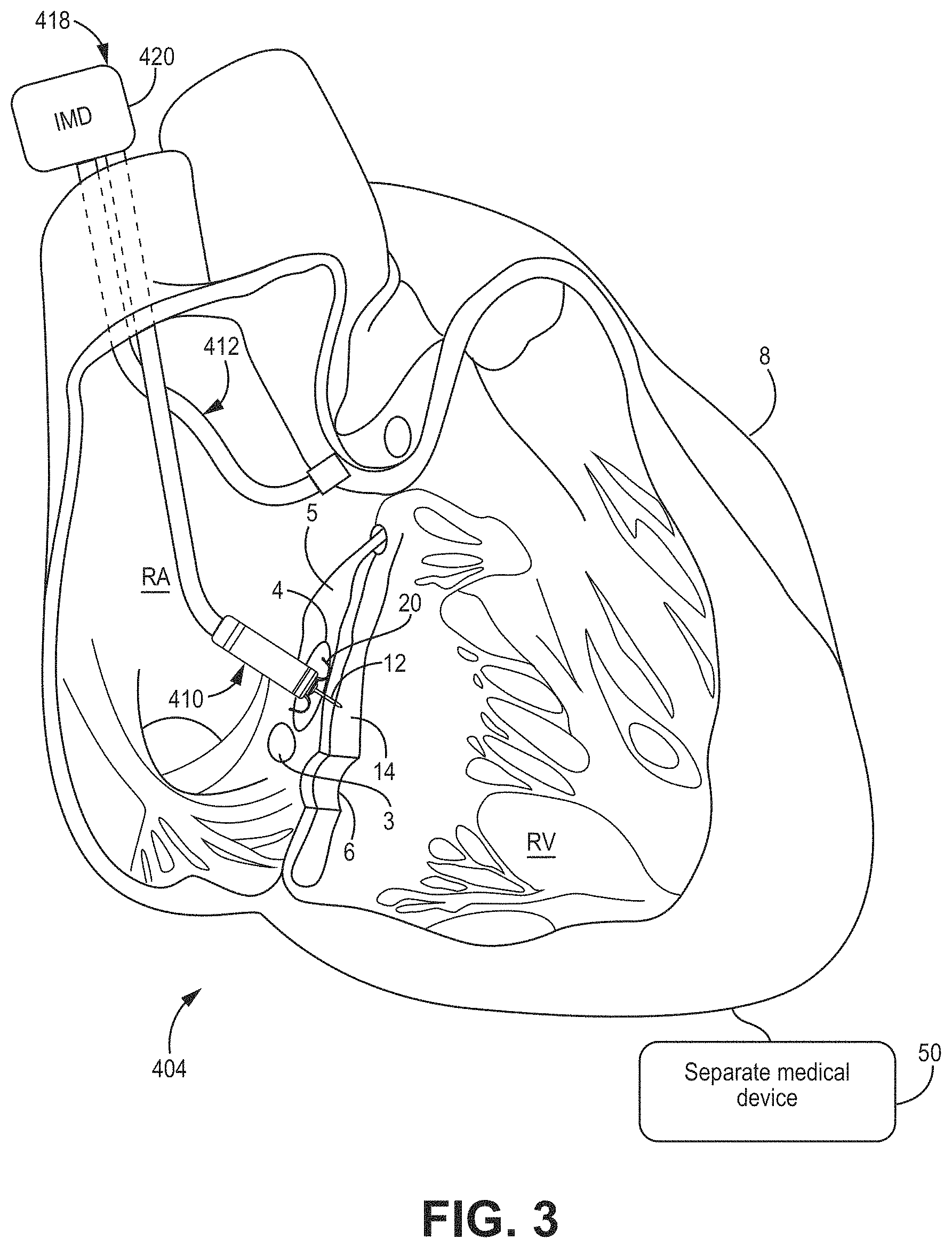
[0056] With reference to FIG. 3, a cardiac therapy system 404 may include a leaded medical device 418 similar to the leaded medical device 408 of FIG. 2, except that the device 418 includes two implantable leads 410, 412. In particular, the implantable lead 412 may include an electrode (e.g., a right-atrial electrode) coupled to a distal end region of the lead 412 and may be implanted in a different location than lead 410. In some embodiments, lead 412 is implanted in a different region of the right atrium. In some embodiments, each lead 410, 412 may contribute one channel of a dual-channel device 418. For example, lead 410 may sense activity or deliver pacing to the left ventricle (LV) when the tissue-piercing electrode of the tissue-piercing electrode assembly 12 is implanted, for example, in the same or similar manner as described with respect to FIG. 1, and lead 412 may sense activity or deliver pacing to the right atrium (RA).
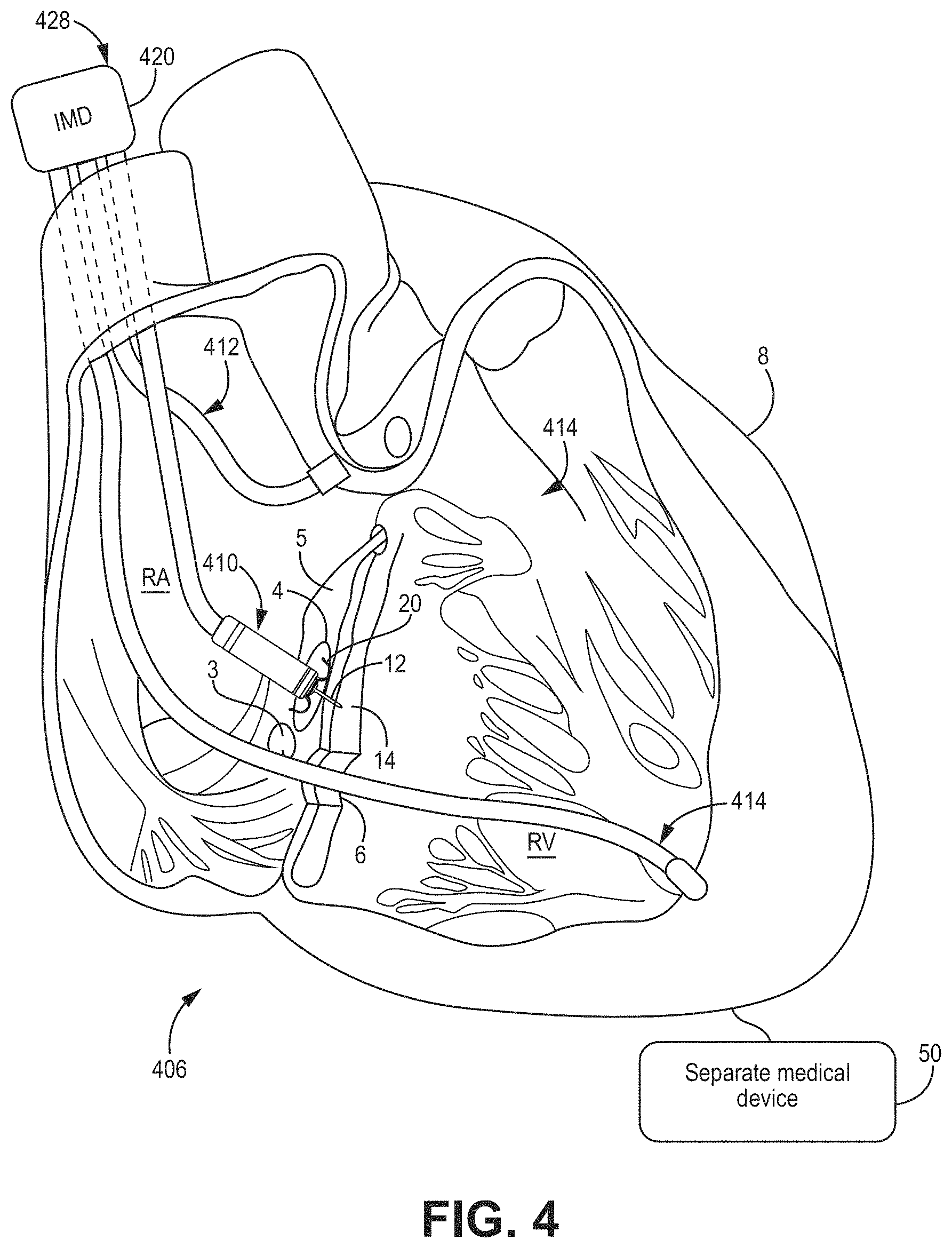
[0057] With reference to FIG. 4, a cardiac therapy system 406 may include a leaded medical device 428 similar to the leaded medical device 418 of FIG. 3 except that device 428 includes three implantable leads 410, 412, 414. In particular, implantable lead 414 may include an electrode (e.g., a right ventricular electrode) coupled to a distal end region of the lead 414 and may be implanted in a different location than leads 410, 412. As illustrated, implantable lead 414 extends from the right atrium (RA) to the right ventricle (RV) through tricuspid valve 6. In some embodiments, lead 414 is implanted in a region of the right ventricle. In some embodiments, each lead 410, 412, 414 may contribute one channel to a multi-channel device 428. For example, lead 410 may sense activity or deliver pacing to the left ventricle (LV) when the tissue-piercing electrode assembly 12 is implanted, for example, in the same or similar manner as described with respect to FIG. 1, lead 412 may sense activity from the delivery of pacing to the RA, and lead 414 may sense activity or deliver pacing to the RV.
[0058] In some embodiments, a pacing delay between the RV electrode on lead 414 to pace the RV and the LV electrode on lead 410 to pace the LV (e.g., RV-LV pacing delay, or more generally, VV pacing delay) may be calibrated or optimized, for example, using a separate medical device, such as an electrode apparatus (e.g., ECG belt). Various methods may be used to calibrate or optimize the VV delay. In some embodiments, the medical device 428 may be used to test pacing at a plurality of different VV delays. For example, the RV may be paced ahead of the LV by about 80, 60, 40, and 20 milliseconds (ms) and the LV may be paced ahead of the RV by about 80, 60, 40, and 20 ms, as well as simultaneous RV-LV pacing (e.g., about 0 ms VV pacing delay). The medical device 428 may then be configured, for example, automatically, to select a VV pacing delay that, when used for pacing, corresponds to a minimal electrical dyssynchrony measured using the electrode apparatus. The test pacing at different VV pacing delays may be performed using a particular AV delay, such as a nominal AV delay set by the medical device 428 or at a predetermined optimal AV delay based on patient characteristics.
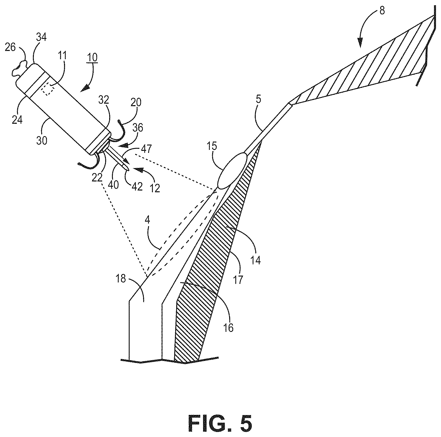
[0059] FIG. 5 is an enlarged conceptual diagram of the intracardiac medical device 10 of FIG. 1 and anatomical structures of the patient's heart 8. In particular, the device 10 is configured to sense electrical activity and/or deliver pacing therapy. The intracardiac device 10 may include a housing 30. The housing 30 may define a hermetically-sealed internal cavity in which internal components of the device 10 reside, such as a sensing circuit, therapy delivery circuit, control circuit, memory, telemetry circuit, other optional sensors, and a power source as generally described in conjunction with FIG. 8. The housing 30 may be formed from an electrically conductive material including titanium or titanium alloy, stainless steel, MP35N (a non-magnetic nickel-cobalt-chromium-molybdenum alloy), platinum alloy, or other bio-compatible metal or metal alloy. In other examples, the housing 30 may be formed from a non-conductive material including ceramic, glass, sapphire, silicone, polyurethane, epoxy, acetyl co-polymer plastics, polyether ether ketone (PEEK), a liquid crystal polymer, or other biocompatible polymer.
[0060] In at least one embodiment, the housing 30 may be described as extending between a distal end region 32 and a proximal end region 34 in a generally cylindrical shape to facilitate catheter delivery. In other embodiments, the housing 30 may be prismatic or any other shape to perform the functionality and utility described herein. The housing 30 may include a delivery tool interface member 26, e.g., at the proximal end region 34, for engaging with a delivery tool during implantation of the device 10.
[0061] All or a portion of the housing 30 may function as an electrode during cardiac therapy, for example, in sensing and/or pacing. In the example shown, the housing-based electrode 24 is shown to circumscribe a proximal portion (e.g., closer to the proximal end region 34 than the distal end region 32) of the housing 30. When the housing 30 is formed from an electrically conductive material, such as a titanium alloy or other examples listed above, portions of the housing 30 may be electrically insulated by a non-conductive material, such as a coating of parylene, polyurethane, silicone, epoxy, or other biocompatible polymer, leaving one or more discrete areas of conductive material exposed to define the proximal housing-based electrode 24. When the housing 30 is formed from a non-conductive material, such as a ceramic, glass or polymer material, an electrically conductive coating or layer, such as a titanium, platinum, stainless steel, or alloys thereof, may be applied to one or more discrete areas of the housing 30 to form the proximal housing-based electrode 24. In other examples, the proximal housing-based electrode 24 may be a component, such as a ring electrode, that is mounted or assembled onto the housing 30. The proximal housing-based electrode 24 may be electrically coupled to internal circuitry of the device 10, e.g., via the electrically-conductive housing 30 or an electrical conductor when the housing 30 is a non-conductive material.
[0062] In the example shown, the proximal housing-based electrode 24 is located nearer to the housing proximal end region 34 than the housing distal end region 32 and is therefore referred to as a "proximal housing-based electrode" 24. In other examples, however, the housing-based electrode 24 may be located at other positions along the housing 30, e.g., more distal relative to the position shown.
[0063] At the distal end region 32, the device 10 may include a distal fixation and electrode assembly 36, which may include one or more fixation members 20 and one or more dart electrode assemblies 12 of equal or unequal length. In one example, a single dart electrode assembly 12 includes a shaft 40 extending distally away from the housing distal end region 32 and one or more electrode elements, such as a tip electrode 42 at or near the free, distal end region of the shaft 40. The tip electrode 42 may have a conical or hemispherical distal tip with a relatively narrow tip-diameter (e.g., less than about 1 millimeter (mm)) for penetrating into and through tissue layers without using a sharpened tip or needle-like tip having sharpened or beveled edges.
[0064] The shaft 40 of the dart electrode assembly 12 may be a normally straight member and may be rigid. In other embodiments, the shaft 40 may be described as being relatively stiff but still possessing limited flexibility in lateral directions. Further, the shaft 40 may be non-rigid to allow some lateral flexing with heart motion. However, in a relaxed state, when not subjected to any external forces, the shaft 40 may maintain a straight position as shown to hold the tip electrode 42 spaced apart from the housing distal end region 32 at least by the height 47 of the shaft 40. In other words, the dart electrode assembly 12 may be described as resilient.
[0065] The dart electrode assembly 12 may be configured to pierce through one or more tissue layers to position the tip electrode 42 within a desired tissue layer, e.g., the ventricular myocardium. As such, the height 47, or length, of the shaft 40 may correspond to the expected pacing site depth, and the shaft 40 may have a relatively high compressive strength along its longitudinal axis to resist bending in a lateral or radial direction when pressed against the implant region 4. If a second dart electrode assembly 12 is employed, its length may be unequal to the expected pacing site depth and may be configured to act as an indifferent electrode for delivering of pacing energy to the tissue. A longitudinal axial force may be applied against the tip electrode 42, e.g., by applying a longitudinal pushing force to the proximal end region 34 of the housing 30, to advance the dart electrode assembly 12 into the tissue within the target implant region. The shaft 40 may be described as longitudinally non-compressive and/or elastically deformable in lateral or radial directions when subjected to lateral or radial forces to allow temporary flexing, e.g., with tissue motion, but may return to its normally straight position when lateral forces diminish. When the shaft 40 is not exposed to any external force, or to only a force along its longitudinal central axis, the shaft 40 may retain a straight, linear position as shown.
[0066] The one or more fixation members 20 may be described as one or more "tines" having a normally curved position. The tines may be held in a distally extended position within a delivery tool. The distal tips of tines may penetrate the heart tissue to a limited depth before elastically curving back proximally into the normally curved position (shown) upon release from the delivery tool. Further, the fixation members 20 may include one or more aspects described in, for example, U.S. Pat. No. 9,675,579 (Grubac et al.), issued 13 Jun. 2017, and U.S. Pat. No. 9,119,959 (Rys et al.), issued 1 Sep. 2015, each of which is incorporated herein by reference in its entirety.
[0067] In some examples, the distal fixation and electrode assembly 36 includes a distal housing-based electrode 22. In the case of using the device 10 as a pacemaker for multiple chamber pacing (e.g., dual- or triple-chamber pacing) and sensing, the tip electrode 42 may be used as a cathode electrode paired with the proximal housing-based electrode 24 serving as a return anode electrode. Alternatively, the distal housing-based electrode 22 may serve as a return anode electrode paired with tip electrode 42 for sensing ventricular signals and delivering ventricular pacing pulses. In other examples, the distal housing-based electrode 22 may be a cathode electrode for sensing atrial signals and delivering pacing pulses to the atrial myocardium in the target implant region 4. When the distal housing-based electrode 22 serves as an atrial cathode electrode, the proximal housing-based electrode 24 may serve as the return anode paired with the tip electrode 42 for ventricular pacing and sensing and as the return anode paired with the distal housing-based electrode 22 for atrial pacing and sensing.
[0068] As shown in this illustration, the target implant region 4 in some pacing applications is along the atrial endocardium 18, generally inferior to the AV node 15 and the His bundle 5. The dart electrode assembly 12 may at least partially define the height 47, or length, of the shaft 40 for penetrating through the atrial endocardium 18 in the target implant region 4, through the central fibrous body 16, and into the ventricular myocardium 14 without perforating through the ventricular endocardial surface 17. When the height 47, or length, of the dart electrode assembly 12 is fully advanced into the target implant region 4, the tip electrode 42 may rest within the ventricular myocardium 14, and the distal housing-based electrode 22 may be positioned in intimate contact with or close proximity to the atrial endocardium 18. The dart electrode assembly 12 may have a total combined height 47, or length, of the tip electrode 42 and the shaft 40 from about 3 mm to about 8 mm in various examples. The diameter of the shaft 40 may be less than about 2 mm, and may be about 1 mm or less, or even about 0.6 mm or less.
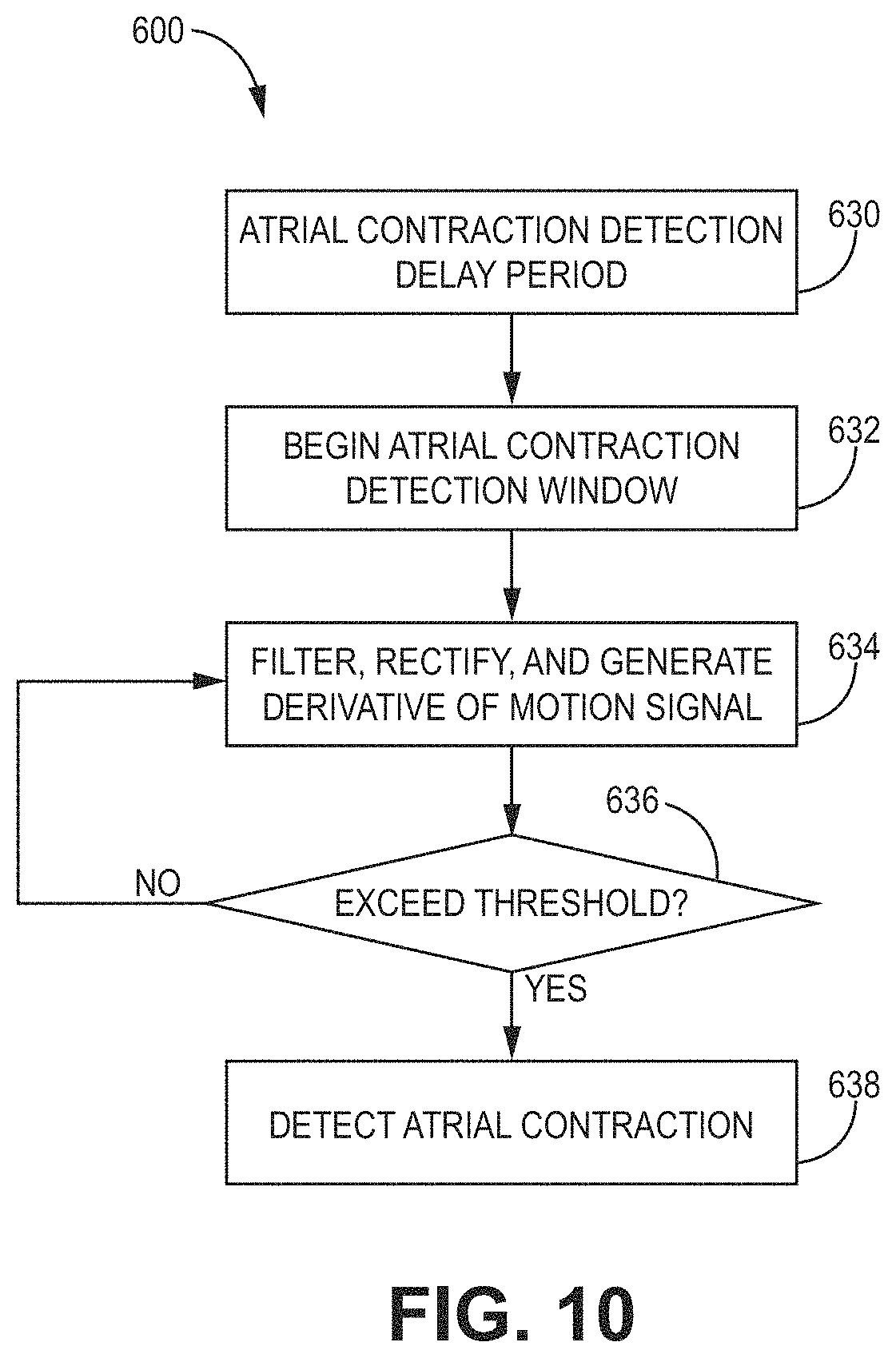
[0069] The device 10 may include an acoustic or motion detector 11 within the housing 30. The acoustic or motion detector 11 may be operably coupled to one or more a control circuit 80 (FIG. 8), a sensing circuit 86 (FIG. 8), or therapy delivery circuit 84 (FIG. 8). In some embodiments, the acoustic or motion detector 11 may be used with methods 600, 650, or 800 as shown in FIGS. 10-12. The acoustic or motion detector 11 may be used to monitor mechanical activity, such as atrial mechanical activity (e.g., an atrial contraction) and/or ventricular mechanical activity (e.g., a ventricular contraction). In some embodiments, the acoustic or motion detector 11 may be used to detect right-atrial mechanical activity. A non-limiting example of an acoustic or motion detector 11 includes an accelerometer or microphone. In some embodiments, the mechanical activity detected by the acoustic or motion detector 11 may be used to supplement or replace electrical activity detected by one or more of the electrodes of the device 10. For example, the acoustic or motion detector 11 may be used in addition to, or as an alternative to, the proximal housing-based electrode 24.
[0070] The acoustic or motion detector 11 may also be used for rate response detection or to provide a rate-responsive 1 MB. Various techniques related to rate response may be described in U.S. Pat. No. 5,154,170 (Bennett et al.), issued Oct. 13, 1992, entitled "Optimization for rate responsive cardiac pacemaker," and U.S. Pat. No. 5,562,711 (Yerich et al.), issued Oct. 8, 1996, entitled "Method and apparatus for rate-responsive cardiac pacing," each of which is incorporated herein by reference in its entirety.
[0071] In various embodiments, acoustic or motion detector 11 (or motion sensor) may be used as an HS sensor and may be implemented as a microphone or a 1-, 2- or 3-axis accelerometer. In one embodiment, the acoustical sensor is implemented as a piezoelectric crystal mounted within an implantable medical device housing and responsive to the mechanical motion associated with heart sounds. The piezoelectric crystal may be a dedicated HS sensor or may be used for multiple functions. In the illustrative embodiment shown, the acoustical sensor is embodied as a piezoelectric crystal that is also used to generate a patient alert signal in the form of a perceptible vibration of the IMD housing. Upon detecting an alert condition, control circuit 80 may cause patient alert control circuitry to generate an alert signal by activating the piezoelectric crystal.
[0072] The control circuit may be used to control whether the piezoelectric crystal is used in a "listening mode" to sense HS signals by HS sensing circuitry or in an "output mode" to generate a patient alert. During patient alert generation, HS sensing circuitry may be temporarily decoupled from the HS sensor by control circuitry.
[0073] Examples of other embodiments of acoustical sensors that may be adapted for implementation with the techniques of the present disclosure may be described generally in U.S. Pat. No. 4,546,777 (Groch, et al.), U.S. Pat. No. 6,869,404 (Schulhauser, et al.), U.S. Pat. No. 5,554,177 (Kieval, et al.), and U.S. Pat. No. 7,035,684 (Lee, et al.), each of which is incorporated herein by reference in its entirety.
[0074] Various types of acoustical sensors may be used. The acoustical sensor may be any implantable or external sensor responsive to one or more of the heart sounds generated as described in the foregoing and thereby produces an analog electrical signal correlated in time and amplitude to the heart sounds. The analog signal may be then be processed, which may include digital conversion, by the HS sensing module to obtain HS parameters, such as amplitudes or relative time intervals, as derived by HS sensing module or control circuit 80. The acoustical sensor and HS sensing module may be incorporated in an IMD capable of delivering CRT or another cardiac therapy being optimized or may be implemented in a separate device having wired or wireless communication with IMD or an external programmer or computer used during a pace-parameter optimization procedure as described herein.
[0075] FIG. 6 is a two-dimensional (2D) ventricular map 300 of a patient's heart (e.g., a top-down view) showing the left ventricle 320 in a standard 17 segment view and the right ventricle 322. The map 300 includes a plurality of areas 326 corresponding to different regions of a human heart. As illustrated, the areas 326 are numerically labeled 1-17 (e.g., which correspond to 17 segments of the left ventricle of a human heart). Areas 326 of the map 300 may include basal anterior area 1, basal anteroseptal area 2, basal inferoseptal area 3, basal inferior area 4, basal inferolateral area 5, basal anterolateral area 6, mid-anterior area 7, mid-anteroseptal area 8, mid-inferoseptal area 9, mid-inferior area 10, mid-inferolateral area 11, mid-anterolateral area 12, apical anterior area 13, apical septal area 14, apical inferior area 15, apical lateral area 16, and apex area 17. The inferoseptal and anteroseptal areas of the right ventricle 322 are also illustrated, as well as the right bundle branch (RBB) and left bundle branch (LBB).
[0076] In some embodiments, any of the tissue-piercing electrodes of the present disclosure may be implanted in the basal region, septal region, or basal-septal region of the left ventricular myocardium of the patient's heart. In particular, the tissue-piercing electrode may be implanted from the triangle of Koch region of the right atrium through the right-atrial endocardium and central fibrous body.
[0077] Once implanted, the tissue-piercing electrode may be positioned in the target implant region 4 (FIGS. 1-5), such as the basal region, septal region, or basal-septal region of the left ventricular myocardium. With reference to map 300, the basal region includes one or more of the basal anterior area 1, basal anteroseptal area 2, basal inferoseptal area 3, basal inferior area 4, mid-anterior area 7, mid-anteroseptal area 8, mid-inferoseptal area 9, and mid-inferior area 10. With reference to map 300, the septal region includes one or more of the basal anteroseptal area 2, basal anteroseptal area 3, mid-anteroseptal area 8, mid-inferoseptal area 9, and apical septal area 14.
[0078] In some embodiments, the tissue-piercing electrode may be positioned in the basal septal region of the left ventricular myocardium when implanted. The basal septal region may include one or more of the basal anteroseptal area 2, basal inferoseptal area 3, mid-anteroseptal area 8, and mid-inferoseptal area 9.
[0079] In some embodiments, the tissue-piercing electrode may be positioned in the inferior/posterior basal septal region of the left ventricular myocardium when implanted. In some cases, the inferior/posterior basal septal region may be described as the high inferior/posterior basal septal region. In some embodiments, the tissue-piercing electrode may be positioned in the posterior superior process of the left ventricle. In some embodiments, the tissue-piercing electrode may be positioned in the high inferior/posterior basal septal region of the left ventricular myocardium when implanted. The inferior/posterior basal septal region of the left ventricular myocardium may include a portion of one or more of the basal inferoseptal area 3 and mid-inferoseptal area 9 (e.g., the basal inferoseptal area only, the mid-inferoseptal area only, or both the basal inferoseptal area and the mid-inferoseptal area). For example, the inferior/posterior basal septal region may include region 324 illustrated generally as a dashed-line boundary. As shown, the dashed line boundary represents an approximation of where the inferior/posterior basal septal region is located, which may take a somewhat different shape or size depending on the particular application.
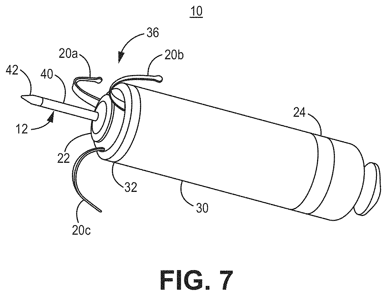
[0080] FIG. 7 is a three-dimensional perspective view of the device 10 capable of calibrating pacing therapy and/or delivering pacing therapy. As shown, the distal fixation and electrode assembly 36 includes the distal housing-based electrode 22 implemented as a ring electrode. The distal housing-based electrode 22 may be positioned in intimate contact with or operative proximity to atrial tissue when fixation member tines 20a, 20b, and 20c of the fixation members 20, engage with the atrial tissue. The tines 20a, 20b, and 20c, which may be elastically deformable, may be extended distally during delivery of device 10 to the implant site. For example, the tines 20a, 20b, and 20c may pierce the atrial endocardial surface as the device 10 is advanced out of the delivery tool and flex back into their normally curved position (as shown) when no longer constrained within the delivery tool. As the tines 20a, 20b, and 20c curve back into their normal position, the fixation member 20 may pull the distal fixation member and electrode assembly 36 toward the atrial endocardial surface. As the distal fixation member and electrode assembly 36 is pulled toward the atrial endocardium, the tip electrode 42 may be advanced through the atrial myocardium and the central fibrous body and into the ventricular myocardium. The distal housing-based electrode 22 may then be positioned against the atrial endocardial surface.
[0081] The distal housing-based electrode 22 may include a ring formed of an electrically conductive material, such as titanium, platinum, iridium, or alloys thereof. The distal housing-based electrode 22 may be a single, continuous ring electrode. In other examples, portions of the ring may be coated with an electrically insulating coating, e.g., parylene, polyurethane, silicone, epoxy, or another insulating coating, to reduce the electrically conductive surface area of the ring electrode. For instance, one or more sectors of the ring may be coated to separate two or more electrically conductive exposed surface areas of the distal housing-based electrode 22. Reducing the electrically conductive surface area of the distal housing-based electrode 22, e.g., by covering portions of the electrically conductive ring with an insulating coating, may increase the electrical impedance of the distal housing-based electrode 22, and thereby, reduce the current delivered during a pacing pulse that captures the myocardium, e.g., the atrial myocardial tissue. A lower current drain may conserve the power source, e.g., one or more rechargeable or non-rechargeable batteries, of the device 10.
[0082] As described above, the distal housing-based electrode 22 may be configured as an atrial cathode electrode for delivering pacing pulses to the atrial tissue at the implant site in combination with the proximal housing-based electrode 24 as the return anode. The electrodes 22 and 24 may be used to sense atrial P-waves for use in controlling atrial pacing pulses (delivered in the absence of a sensed P-wave) and for controlling atrial-synchronized ventricular pacing pulses delivered using the tip electrode 42 as a cathode and the proximal housing-based electrode 24 as the return anode. In other examples, the distal housing-based electrode 22 may be used as a return anode in conjunction with the cathode tip electrode 42 for ventricular pacing and sensing.
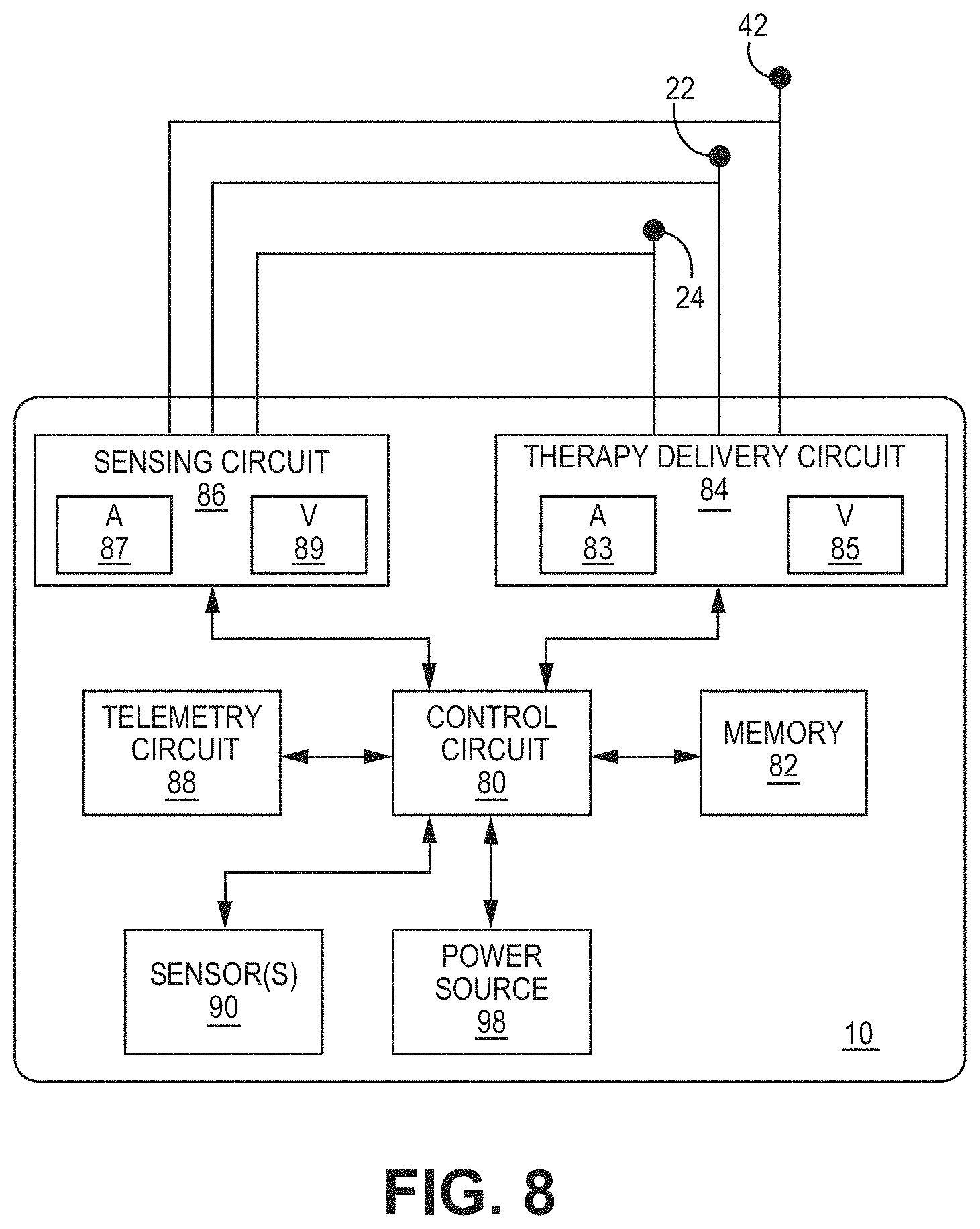
[0083] FIG. 8 is a block diagram of circuitry that may be enclosed within the housing 30 (FIG. 7) to provide the functions of calibrating pacing therapy and/or delivering pacing therapy, using the device 10 according to one example or within the housings of any other medical devices described herein (e.g., device 408 of FIG. 2, device 418 of FIG. 3, device 428 of FIG. 4, or device 710 of FIG. 9). The separate medical device 50 (FIGS. 1-4) may include some or all the same components, which may be configured in a similar manner. The electronic circuitry enclosed within housing 30 may include software, firmware, and hardware that cooperatively monitor atrial and ventricular electrical cardiac signals, determine when a cardiac therapy is necessary, and/or deliver electrical pulses to the patient's heart according to programmed therapy mode and pulse control parameters. The electronic circuitry may include a control circuit 80 (e.g., including processing circuitry), a memory 82, a therapy delivery circuit 84, a sensing circuit 86, and/or a telemetry circuit 88. In some examples, the device 10 includes one or more sensors 90 for producing a signal that is correlated to a physiological function, state, or condition of the patient, such as a patient activity sensor, for use in determining a need for pacing therapy and/or controlling a pacing rate. For example, one sensor 90 may include an inertial measurement unit (e.g., accelerometer) to measure motion.
[0084] The power source 98 may provide power to the circuitry of the device 10 including each of the components 80, 82, 84, 86, 88, 90 as needed. The power source 98 may include one or more energy storage devices, such as one or more rechargeable or non-rechargeable batteries. The connections (not shown) between the power source 98 and each of the components, such as sensors 80, 82, 84, 86, 88, 90, may be understood from the general block diagram illustrated to one of ordinary skill in the art. For example, the power source 98 may be coupled to one or more charging circuits included in the therapy delivery circuit 84 for providing the power used to charge holding capacitors included in the therapy delivery circuit 84 that are discharged at appropriate times under the control of the control circuit 80 for delivering pacing pulses, e.g., according to a dual chamber pacing mode such as DDI(R). The power source 98 may also be coupled to components of the sensing circuit 86, such as sense amplifiers, analog-to-digital converters, switching circuitry, etc., sensors 90, the telemetry circuit 88, and the memory 82 to provide power to the various circuits.
[0085] The functional blocks shown represent functionality included in the device 10 and may include any discrete and/or integrated electronic circuit components that implement analog, and/or digital circuits capable of producing the functions attributed to the medical device 10 herein. The various components may include processing circuitry, such as an application specific integrated circuit (ASIC), an electronic circuit, a processor (shared, dedicated, or group), and memory that execute one or more software or firmware programs, a combinational logic circuit, state machine, or other suitable components or combinations of components that provide the described functionality. The particular form of software, hardware, and/or firmware employed to implement the functionality disclosed herein will be determined primarily by the particular system architecture employed in the medical device and by the particular detection and therapy delivery methodologies employed by the medical device.
[0086] The memory 82 may include any volatile, non-volatile, magnetic, or electrical non-transitory computer-readable storage media, such as random-access memory (RAM), read-only memory (ROM), non-volatile RAM (NVRAM), electrically-erasable programmable ROM (EEPROM), flash memory, or any other memory device. Furthermore, the memory 82 may include a non-transitory computer-readable media storing instructions that, when executed by one or more processing circuits, cause the control circuit 80 and/or other processing circuitry to calibrate pacing therapy and/or perform a single, dual, or triple-chamber calibrated pacing therapy (e.g., single or multiple chamber pacing), or other cardiac therapy functions (e.g., sensing or delivering therapy), attributed to the device 10. The non-transitory computer-readable media storing the instructions may include any of the media listed above.
[0087] The control circuit 80 may communicate, e.g., via a data bus, with the therapy delivery circuit 84 and the sensing circuit 86 for sensing cardiac electrical signals and controlling delivery of cardiac electrical stimulation therapies in response to sensed cardiac events, e.g., P-waves and R-waves, or the absence thereof. The tip electrode 42, the distal housing-based electrode 22, and the proximal housing-based electrode 24 may be electrically coupled to the therapy delivery circuit 84 for delivering electrical stimulation pulses to the patient's heart and to the sensing circuit 86 and for sensing cardiac electrical signals.
[0088] The sensing circuit 86 may include an atrial (A) sensing channel 87 and a ventricular (V) sensing channel 89. The distal housing-based electrode 22 and the proximal housing-based electrode 24 may be coupled to the atrial sensing channel 87 for sensing atrial signals, e.g., P-waves attendant to the depolarization of the atrial myocardium. In examples that include two or more selectable distal housing-based electrodes, the sensing circuit 86 may include switching circuitry for selectively coupling one or more of the available distal housing-based electrodes to cardiac event detection circuitry included in the atrial sensing channel 87. Switching circuitry may include a switch array, switch matrix, multiplexer, or any other type of switching device suitable to selectively couple components of the sensing circuit 86 to selected electrodes. The tip electrode 42 and the proximal housing-based electrode 24 may be coupled to the ventricular sensing channel 89 for sensing ventricular signals, e.g., R-waves attendant to the depolarization of the ventricular myocardium.
[0089] Each of the atrial sensing channel 87 and the ventricular sensing channel 89 may include cardiac event detection circuitry for detecting P-waves and R-waves, respectively, from the cardiac electrical signals received by the respective sensing channels. The cardiac event detection circuitry included in each of the channels 87 and 89 may be configured to amplify, filter, digitize, and rectify the cardiac electrical signal received from the selected electrodes to improve the signal quality for detecting cardiac electrical events. The cardiac event detection circuitry within each channel 87 and 89 may include one or more sense amplifiers, filters, rectifiers, threshold detectors, comparators, analog-to-digital converters (ADCs), timers, or other analog or digital components. A cardiac event sensing threshold, e.g., a P-wave sensing threshold and an R-wave sensing threshold, may be automatically adjusted by each respective sensing channel 87 and 89 under the control of the control circuit 80, e.g., based on timing intervals and sensing threshold values determined by the control circuit 80, stored in the memory 82, and/or controlled by hardware, firmware, and/or software of the control circuit 80 and/or the sensing circuit 86.
[0090] Upon detecting a cardiac electrical event based on a sensing threshold crossing, the sensing circuit 86 may produce a sensed event signal that is passed to the control circuit 80. For example, the atrial sensing channel 87 may produce a P-wave sensed event signal in response to a P-wave sensing threshold crossing. The ventricular sensing channel 89 may produce an R-wave sensed event signal in response to an R-wave sensing threshold crossing. The sensed event signals may be used by the control circuit 80 for setting pacing escape interval timers that control the basic time intervals used for scheduling cardiac pacing pulses. A sensed event signal may trigger or inhibit a pacing pulse depending on the particular programmed pacing mode. For example, a P-wave sensed event signal received from the atrial sensing channel 87 may cause the control circuit 80 to inhibit a scheduled atrial pacing pulse and schedule a ventricular pacing pulse at a programmed atrioventricular (AV) pacing interval. If an R-wave is sensed before the AV pacing interval expires, the ventricular pacing pulse may be inhibited. If the AV pacing interval expires before the control circuit 80 receives an R-wave sensed event signal from the ventricular sensing channel 89, the control circuit 80 may use the therapy delivery circuit 84 to deliver the scheduled ventricular pacing pulse synchronized to the sensed P-wave.
[0091] In some examples, the device 10 may be configured to deliver a variety of pacing therapies including bradycardia pacing, cardiac resynchronization therapy, post-shock pacing, and/or tachycardia-related therapy, such as ATP, among others. For example, the device 10 may be configured to detect non-sinus tachycardia and deliver ATP. The control circuit 80 may determine cardiac event time intervals, e.g., P-P intervals between consecutive P-wave sensed event signals received from the atrial sensing channel 87, R-R intervals between consecutive R-wave sensed event signals received from the ventricular sensing channel 89, and P-R and/or R-P intervals received between P-wave sensed event signals and R-wave sensed event signals. These intervals may be compared to tachycardia detection intervals for detecting non-sinus tachycardia. Tachycardia may be detected in a given heart chamber based on a threshold number of tachycardia detection intervals being detected.
[0092] The therapy delivery circuit 84 may include atrial pacing circuit 83 and ventricular pacing circuit 85. Each pacing circuit 83, 85 may include charging circuitry, one or more charge storage devices such as one or more low voltage holding capacitors, an output capacitor, and/or switching circuitry that controls when the holding capacitor(s) are charged and discharged across the output capacitor to deliver a pacing pulse to the pacing electrode vector coupled to respective pacing circuits 83, 85. The tip electrode 42 and the proximal housing-based electrode 24 may be coupled to the ventricular pacing circuit 85 as a bipolar cathode and anode pair for delivering ventricular pacing pulses, e.g., upon expiration of an AV or VV pacing interval set by the control circuit 80 for providing atrial-synchronized ventricular pacing and a basic lower ventricular pacing rate.
[0093] The atrial pacing circuit 83 may be coupled to the distal housing-based electrode 22 and the proximal housing-based electrode 24 to deliver atrial pacing pulses. The control circuit 80 may set one or more atrial pacing intervals according to a programmed lower pacing rate or a temporary lower rate set according to a rate-responsive sensor-indicated pacing rate. Atrial pacing circuit may be controlled to deliver an atrial pacing pulse if the atrial pacing interval expires before a P-wave sensed event signal is received from the atrial sensing channel 87. The control circuit 80 starts an AV pacing interval in response to a delivered atrial pacing pulse to provide synchronized multiple chamber pacing (e.g., dual- or triple-chamber pacing).
[0094] Charging of a holding capacitor of the atrial or ventricular pacing circuit 83, 85 to a programmed pacing voltage amplitude and discharging of the capacitor for a programmed pacing pulse width may be performed by the therapy delivery circuit 84 according to control signals received from the control circuit 80. For example, a pace timing circuit included in the control circuit 80 may include programmable digital counters set by a microprocessor of the control circuit 80 for controlling the basic pacing time intervals associated with various single-chamber or multiple-chamber pacing (e.g., dual- or triple-chamber pacing) modes or anti-tachycardia pacing sequences. The microprocessor of the control circuit 80 may also set the amplitude, pulse width, polarity, or other characteristics of the cardiac pacing pulses, which may be based on programmed values stored in the memory 82.
[0095] The device 10 may include other sensors 90 for sensing signals from the patient for use in determining a need for and/or controlling electrical stimulation therapies delivered by the therapy delivery circuit 84. In some examples, a sensor indicative of a need for increased cardiac output may include a patient activity sensor, such as an accelerometer. An increase in the metabolic demand of the patient due to increased activity as indicated by the patient activity sensor may be determined by the control circuit 80 for use in determining a sensor-indicated pacing rate.
[0096] Control parameters utilized by the control circuit 80 for sensing cardiac events and controlling pacing therapy delivery may be programmed into the memory 82 via the telemetry circuit 88, which may also be described as a communication interface. The telemetry circuit 88 includes a transceiver and antenna for communicating with an external device, such as a programmer or home monitor, using radio frequency communication or other communication protocols. The control circuit 80 may use the telemetry circuit 88 to receive downlink telemetry from and send uplink telemetry to the external device. In some cases, the telemetry circuit 88 may be used to transmit and receive communication signals to/from another medical device implanted in the patient.
[0097] FIG. 9 is a three-dimensional perspective view of another leadless intracardiac medical device 710 that may be configured for calibrating pacing therapy and/or delivering pacing therapy for single or multiple chamber cardiac therapy (e.g., dual- or triple-chamber cardiac therapy) according to another example. The device 710 may include a housing 730 having an outer sidewall 735, shown as a cylindrical outer sidewall, extending from a housing distal end region 732 to a housing proximal end region 734. The housing 730 may enclose electronic circuitry configured to perform single- or multiple-chamber cardiac therapy, including atrial and ventricular cardiac electrical signal sensing and pacing the atrial and ventricular chambers. The delivery tool interface member 726 is shown on the housing proximal end region 734.
[0098] A distal fixation and electrode assembly 736 may be coupled to the housing distal end region 732. The distal fixation and electrode assembly 736 may include an electrically insulative distal member 772 coupled to the housing distal end region 732. The tissue-piercing electrode assembly 712 extends away from the housing distal end region 732, and multiple non-tissue piercing electrodes 722 may be coupled directly to the insulative distal member 772. The tissue-piercing electrode assembly 712 extends in a longitudinal direction away from the housing distal end region 732 and may be coaxial with the longitudinal center axis 731 of the housing 730.
[0099] The distal tissue-piercing electrode assembly 712 may include an electrically insulated shaft 740 and a tip electrode 742 (e.g., tissue-piercing electrode). In some examples, the tissue-piercing electrode assembly 712 is an active fixation member including a helical shaft 740 and a distal cathode tip electrode 742. The helical shaft 740 may extend from a shaft distal end region 743 to a shaft proximal end region 741, which may be directly coupled to the insulative distal member 772. The helical shaft 740 may be coated with an electrically insulating material, e.g., parylene or other examples listed herein, to avoid sensing or stimulation of cardiac tissue along the shaft length. The tip electrode 742 is at the shaft distal end region 743 and may serve as a cathode electrode for delivering ventricular pacing pulses and sensing ventricular electrical signals using the proximal housing-based electrode 724 as a return anode when the tip electrode 742 is advanced into ventricular tissue. The proximal housing-based electrode 724 may be a ring electrode circumscribing the housing 730 and may be defined by an uninsulated portion of the longitudinal sidewall 735. Other portions of the housing 730 not serving as an electrode may be coated with an electrically insulating material as described above in conjunction with FIG. 7.
[0100] Using two or more tissue-piercing electrodes (e.g., of any type) penetrating into the LV myocardium may be used for more localized pacing capture and may mitigate ventricular pacing spikes affecting capturing atrial tissue. In some embodiments, multiple tissue-piercing electrodes may include two or more dart-type electrode assemblies (e.g., electrode assembly 12 of FIG. 7), a helical-type electrode (e.g., electrode assembly 712) Non-limiting examples of multiple tissue-piercing electrodes include two dart electrode assemblies, a helix electrode with a dart electrode assembly extending therethrough (e.g., through the center), or dual intertwined helixes. Multiple tissue-piercing electrodes may also be used for bipolar or multi-polar pacing.
[0101] In some embodiments, one or more tissue-piercing electrodes (e.g., of any type) that penetrate into the LV myocardium may be a multi-polar tissue-piercing electrode. A multi-polar tissue-piercing electrode may include one or more electrically active and electrically separate elements, which may enable bipolar or multi-polar pacing from one or more tissue-piercing electrodes.
[0102] Multiple non-tissue piercing electrodes 722 may be provided along a periphery of the insulative distal member 772, peripheral to the tissue-piercing electrode assembly 712. The insulative distal member 772 may define a distal-facing surface 738 of the device 710 and a circumferential surface 739 that circumscribes the device 710 adjacent to the housing longitudinal sidewall 735. Non-tissue piercing electrodes 722 may be formed of an electrically conductive material, such as titanium, platinum, iridium, or alloys thereof. In the illustrated embodiment, six non-tissue piercing electrodes 722 are spaced apart radially at equal distances along the outer periphery of insulative distal member 772. However, two or more non-tissue piercing electrodes 722 may be provided.
[0103] Non-tissue piercing electrodes 722 may be discrete components each retained within a respective recess 774 in the insulative member 772 sized and shaped to mate with the non-tissue piercing electrode 722. In other examples, the non-tissue piercing electrodes 722 may each be an uninsulated, exposed portion of a unitary member mounted within or on the insulative distal member 772. Intervening portions of the unitary member not functioning as an electrode may be insulated by the insulative distal member 772 or, if exposed to the surrounding environment, may be coated with an electrically insulating coating, e.g., parylene, polyurethane, silicone, epoxy, or another insulating coating.
[0104] When the tissue-piercing electrode assembly 712 is advanced into cardiac tissue, at least one non-tissue piercing electrode 722 may be positioned against, in intimate contact with, or in operative proximity to, a cardiac tissue surface for delivering pulses and/or sensing cardiac electrical signals produced by the patient's heart. For example, non-tissue piercing electrodes 722 may be positioned in contact with right-atrial endocardial tissue for pacing and sensing in the atrium when the tissue-piercing electrode assembly 712 is advanced into the atrial tissue and through the central fibrous body until the distal tip electrode 742 is positioned in direct contact with ventricular tissue, e.g., ventricular myocardium and/or a portion of the ventricular conduction system.
[0105] Non-tissue piercing electrodes 722 may be coupled to the therapy delivery circuit 84 and the sensing circuit 86 (see FIG. 8) enclosed by the housing 730 to function collectively as a cathode electrode for delivering atrial pacing pulses and for sensing atrial electrical signals, e.g., P-waves, in combination with the proximal housing-based electrode 724 as a return anode. Switching circuitry included in the sensing circuit 86 may be activated under the control of the control circuit 80 to couple one or more of the non-tissue piercing electrodes to the atrial sensing channel 87. Distal, non-tissue piercing electrodes 722 may be electrically isolated from each other so that each individual one of the electrodes 722 may be individually selected by switching circuitry included in the therapy delivery circuit 84 to serve alone or in a combination of two or more of the electrodes 722 as an atrial cathode electrode. Switching circuitry included in the therapy delivery circuit 84 may be activated under the control of the control circuit 80 to couple one or more of the non-tissue piercing electrodes 722 to the atrial pacing circuit 83. Two or more of the non-tissue piercing electrodes 722 may be selected at a time to operate as a multi-point atrial cathode electrode.
[0106] Certain non-tissue piercing electrodes 722 selected for atrial pacing and/or atrial sensing may be selected based on atrial capture threshold tests, electrode impedance, P-wave signal strength in the cardiac electrical signal, or other factors. For example, a single one or any combination of two or more individual non-tissue piercing electrodes 722 functioning as a cathode electrode that provides an optimal combination of a low pacing capture threshold amplitude and relatively high electrode impedance may be selected to achieve reliable atrial pacing using minimal current drain from the power source 98.
[0107] In some instances, the distal-facing surface 738 may uniformly contact the atrial endocardial surface when the tissue-piercing electrode assembly 712 anchors the housing 730 at the implant site. In that case, all the electrodes 722 may be selected together to form the atrial cathode. Alternatively, every other one of the electrodes 722 may be selected together to form a multi-point atrial cathode having a higher electrical impedance that is still uniformly distributed along the distal-facing surface 738. Alternatively, a subset of one or more electrodes 722 along one side of the insulative distal member 772 may be selected to provide pacing at a desired site that achieves the lowest pacing capture threshold due to the relative location of the electrodes 722 to the atrial tissue being paced.
[0108] In other instances, the distal-facing surface 738 may be oriented at an angle relative to the adjacent endocardial surface depending on the positioning and orientation at which the tissue-piercing electrode assembly 712 enters the cardiac tissue. In this situation, one or more of the non-tissue piercing electrodes 722 may be positioned in contact with the adjacent endocardial tissue closer than other non-tissue piercing electrodes 722, which may be angled away from the endocardial surface. By providing multiple non-tissue piercing electrodes along the periphery of the insulative distal member 772, the angle of the tissue-piercing electrode assembly 712 and the housing distal end region 732 relative to the cardiac surface, e.g., the right-atrial endocardial surface, may not be required to be substantially parallel. Anatomical and positional differences may cause the distal-facing surface 738 to be angled or oblique to the endocardial surface, however, multiple non-tissue piercing electrodes 722 distributed along the periphery of the insulative distal member 772 increase the likelihood of good contact between one or more electrodes 722 and the adjacent cardiac tissue to promote acceptable pacing thresholds and reliable cardiac event sensing using at least a subset of multiple electrodes 722. Contact or fixation circumferentially along the entire periphery of the insulative distal member 772 may not be required.
[0109] The non-tissue piercing electrodes 722 are shown to each include a first portion 722a extending along the distal-facing surface 738 and a second portion 722b extending along the circumferential surface 739. The first portion 722a and the second portion 722b may be continuous, exposed surfaces such that the active electrode surface wraps around a peripheral edge 776 of the insulative distal member 772 that joins the distal facing surface 738 and the circumferential surface 739. The non-tissue piercing electrodes 722 may include one or more of the electrodes 722 along the distal-facing surface 738, one or more electrodes along the circumferential surface 739, one or more electrodes each extending along both of the distal-facing surface 738 and the circumferential surface 739, or any combination thereof. The exposed surface of each of the non-tissue piercing electrodes 722 may be flush with respective distal-facing surfaces 738 and/or circumferential surfaces. In other examples, each of the non-tissue piercing electrodes 722 may have a raised surface that protrudes from the insulative distal member 772. Any raised surface of the electrodes 722, however, may define a smooth or rounded, non-tissue piercing surface.
[0110] The distal fixation and electrode assembly 736 may seal the distal end region of the housing 730 and may provide a foundation on which the electrodes 722 are mounted. The electrodes 722 may be referred to as housing-based electrodes. The electrodes 722 may not be carried by a shaft or other extension that extends the active electrode portion away from the housing 730, like the distal tip electrode 742 residing at the distal tip of the helical shaft 740 extending away from the housing 730. Other examples of non-tissue piercing electrodes presented herein that are coupled to a distal-facing surface and/or a circumferential surface of an insulative distal member include the distal housing-based ring electrode 22 (FIG. 7), the distal housing-based ring electrode extending circumferentially around the assembly 36 (FIG. 7), button electrodes, other housing-based electrodes, and other circumferential ring electrodes. Any non-tissue piercing electrodes directly coupled to a distal insulative member, peripherally to a central tissue-piercing electrode, may be provided to function individually, collectively, or in any combination as a cathode electrode for delivering pacing pulses to adjacent cardiac tissue. When a ring electrode, such as the distal ring electrode 22 and/or a circumferential ring electrode, is provided, portions of the ring electrode may be electrically insulated by a coating to provide multiple distributed non-tissue piercing electrodes along the distal-facing surface and/or the circumferential surface of the insulative distal member.
[0111] The non-tissue piercing electrodes 722 and other examples listed above are expected to provide more reliable and effective atrial pacing and sensing than a tissue-piercing electrode provided along the distal fixation and electrode assembly 736. The atrial chamber walls are relatively thin compared to ventricular chamber walls. A tissue-piercing atrial cathode electrode may extend too deep within the atrial tissue leading to inadvertent sustained or intermittent capture of ventricular tissue. A tissue-piercing atrial cathode electrode may lead to interference with sensing atrial signals due to ventricular signals having a larger signal strength in the cardiac electrical signal received via tissue-piercing atrial cathode electrodes that are closer in physical proximity to the ventricular tissue. The tissue-piercing electrode assembly 712 may be securely anchored into ventricular tissue for stabilizing the implant position of the device 710 and providing reasonable certainty that the tip electrode 742 is sensing and pacing in ventricular tissue while the non-tissue piercing electrodes 722 are reliably pacing and sensing in the atrium. When the device 710 is implanted in the target implant region 4, e.g., as shown in FIG. 1 the ventricular septum, the tip electrode 742 may reach left ventricular tissue for pacing of the left ventricle while the non-tissue piercing electrodes 722 provide pacing and sensing in the right atrium. The tissue-piercing electrode assembly 712 may be in the range of about 4 to about 8 mm in length from the distal-facing surface 738 to reach left ventricular tissue. In some instances, the device 710 may achieve four-chamber pacing by delivering atrial pacing pulses from the atrial pacing circuit 83 via the non-tissue piercing electrodes 722 in the target implant region 4 to achieve bi-atrial (right and left atrial) capture and by delivering ventricular pacing pulses from the ventricular pacing circuit 85 via the tip electrode 742 advanced into ventricular tissue from the target implant region 4 to achieve biventricular (right and left ventricular) capture.
[0112] FIG. 10 shows an illustrative method 600 of detecting atrial activity, for example, using the acoustic or motion detector 11 of FIG. 5, which may be used to represent physiological response information. In particular, method 600 may include detecting an atrial contraction based on analysis of a motion signal (e.g., provided by the motion detector 11) that may be performed by an IMD implanted in the patient's heart. In some embodiments, the motion signal may be provided by an IMD implanted within a ventricle, such as the right ventricle, of the patient's heart. The method 600 may include beginning an atrial contraction detection delay period upon identification of a ventricular activation event 630. The method 600 may include beginning an atrial contraction detection window upon expiration of the atrial contraction delay period 632. The method 600 may include analyzing the motion signal within the atrial contraction detection window.
[0113] The method 600 may include filtering the motion signal within the atrial contraction detection window, rectifying the filtered signal, and generating a derivative signal of the filtered and rectified motion signal 634 within the atrial contraction detection window. The method 600 may include determining whether an amplitude of the derivative signal within the atrial contraction detection window exceeds a threshold 636. In response to determining that the amplitude of the derivative signal within the atrial contraction detection window exceeds the threshold (YES of 636), the method 600 may proceed to detecting atrial contraction 638. Otherwise (NO of 636), the method 600 may return to filtering, rectifying, and generating a derivative signal 634. Various techniques for using a motion detector that provides a motion signal may be described in U.S. Pat. No. 9,399,140 (Cho et al.), issued Jul. 26, 2016, entitled "Atrial contraction detection by a ventricular leadless pacing device for atrio-synchronous ventricular pacing," which is incorporated herein by reference in its entirety.
[0114] As will be described with respect to FIG. 11, heart sounds (HS) may be detected and used to represent physiological response information. described herein, the amplitudes and/or relative time intervals of one or more of the S1 through S4 heart sounds can be useful in optimizing a patient's hemodynamic response to CRT or other cardiac therapies that include cardiac pacing and/or neural stimulation for achieving hemodynamic benefit. The first heart sound, S1, corresponds to the start of ventricular systole. Ventricular systole begins when an action potential conducts through the atrioventricular node (AV node) and quickly depolarizes the ventricular myocardium. This event is distinguished by the QRS complex on the ECG. As the ventricles contract, the pressure in the ventricles begins to rise, causing abrupt closure of the mitral and tricuspid valves between the ventricles and atria as ventricular pressure exceeds atrial pressure. This valve closure may generate S1. S1 generally has a duration of about 150 ms and a frequency on the order of about 20 to 250 Hz. The amplitude of S1 may provide a surrogate measurement of LV contractility. Thus, an increase in S1 amplitude positively may correlate with an improvement in LV contractility. Other measures, like the pre-ejection period measured from the onset of QRS to S1, may also be used as a surrogate of myocardial contractility index. Separation of the closure of the mitral and tricuspid valves due to ventricular dyssynchrony can be observed as separate M1 and T1 peaks in the S1 signal. Merging of the M1 (mitral valve closure sound) and the T1 (tricuspid valve closure sound) can be used as an indication of improved ventricular synchrony.
[0115] Generally, left ventricular pressure (LVP) rises dramatically following the QRS complex of the ECG and closure of the mitral valve and continues to build during ventricular systole until the aortic and pulmonary valves open, ejecting blood into the aorta and pulmonary artery. Ventricular contraction typically continues to cause blood pressure to rise in the ventricles and the aorta and pulmonary artery during the ejection phase. As the contraction diminishes, blood pressure decreases until the aortic and pulmonary valves close.
[0116] The second heart sound, S2, may be generated by the closure of the aortic and pulmonary valves, near the end of ventricular systole and start of ventricular diastole. S2 may, therefore, be correlated to diastolic pressure in the aorta and the pulmonary artery. S2 generally has a duration of about 120 ms and a frequency on the order of 25 to 350 Hz. The time interval between S1 and S2, i.e., S1-S2 time interval may represent the systolic time interval (STI) corresponding to the ventricular isovolumic contraction (pre-ejection) and ejection phase of the cardiac cycle. This S1-S2 time interval may provide a surrogate measurement for stroke volume. Furthermore, the ratio of the pre-ejection period (Q-S1) to S1-S2 time may be used as an index of myocardial contractility.
[0117] The third heart sound, S3, is associated with early, passive diastolic filling of the ventricles, and the fourth heart sound, S4, may be associated with late, active filling of the ventricles due to atrial contraction. The third sound is generally difficult to hear in a normal patient using a stethoscope, and the fourth sound is generally not heard in a normal patient. Presence of the third and fourth heart sounds during an examination using a stethoscope may indicate a pathological condition. The S3 and S4 heart sounds may be used in optimizing pace parameters as they relate to the diastolic function of the heart. Generally, these sounds would be minimized or disappear when an optimal pace parameter is identified. Other aspects of the S1 through S4 heart sounds and timing thereof that may be useful in cardiac pace-parameter optimization as known to one having ordinary skill in the art.
[0118] FIG. 11 is a flowchart 800 of a method for using heart sounds to optimize pace control parameters according to one embodiment. Methods of the present disclosure may include one or more blocks shown in flowchart 800. Other examples of using heart sounds to optimize cardiac therapy are described generally in U.S. Pat. No. 9,643,0134, granted May 9, 2017, entitled "System and method for pacing parameter optimization using heart sounds," which is incorporated herein by reference in its entirety.
[0119] A pace-parameter optimization method may be initiated at block 802. The optimization process may be initiated in response to a user command received via an external programmer. At a time of initial IMD implantation or during office follow-up visits, or during a remote patient monitoring session, a user may initiate an HS-base optimization procedure using an external programmer or networked computer. Additionally, or alternatively, the process shown by flowchart 800 may be an automated process started periodically or in response to sensing a need for therapy delivery or therapy adjustment based on a sensed physiological signal, which may include sensed HS signals.
[0120] At block 804 a pace control parameter to be optimized is selected. A control parameter may be a timing-related parameter, such as an AV interval or VV interval. Pacing vector is another control parameter that may be selected at block 804 for optimization. For example, when a multi-polar lead is used, such as a coronary sinus lead, multiple bipolar or unipolar pacing vectors may be selected for pacing in a given heart chamber. The pacing site associated with a particular pacing vector may have a significant effect on the hemodynamic benefit of pacing therapy. As such, pacing vector is one pace control parameter that may be optimized using methods described herein.
[0121] A pacing sequence is initiated at block 806 using an initial parameter setting for the test parameter selected at block 804. In one embodiment, the AV interval is being optimized, and ventricular pacing is delivered at an initial AV interval setting. It is understood that an initial AV interval setting may be selected at block 806 by first measuring an intrinsic AV interval in a patient having intact AV conduction, i.e., no AV block. An initial AV interval may be a default pacing interval, the last programmed AV interval, or a minimum or maximum AV interval to be tested. Alternatively, if the VV interval is selected for optimization, an intrinsic inter-ventricular conduction time may be measured first and paced VV intervals may be iteratively adjusted beginning at a VV interval longer, shorter, or approximately equal to the intrinsic VV conduction time.
[0122] An iterative process for adjusting the selected test parameter to at least two different settings is performed. The parameter may be adjusted to different settings in any desired order, e.g., increasing, decreasing, random, etc. For example, during adjustment of AV interval, an initial AV interval may be set to just longer than or approximately equal to a measured intrinsic AV conduction time then iteratively decreased down to a minimum AV interval test setting. During pacing using each pace parameter setting, HS signals are acquired at block 808. The iterative process advances to the next test parameter setting at block 812 until all test parameter settings have been applied, as determined at block 810, and HS signals have been recorded for each setting.
[0123] HS signals may be acquired for multiple cardiac cycles to enable ensemble averaging or averaging of HS parameter measurements taken from individual cardiac cycles. It is understood that amplification, filtering, rectification, noise cancellation techniques or other signal processing steps may be used for improving the signal-to-noise ratio of the HS signals and these steps may be different for each of the heart sounds being acquired, which may include any or all types of heart sounds.
[0124] At least one HS parameter measurement is determined from the recorded HS signals for each test parameter setting at block 814. The IMD processor or an external processor, e.g., included in a programmer, or a combination of both may perform the HS signal analysis described herein. In one embodiment, S1 and S2 are recorded and HS parameters are measured using the S1 and S2 signals at block 814. For example, the amplitude of S1, the V-S2 interval (where the V event may be a V pace or a sensed R-wave), and the S1-S2 interval are measured. The presence of S3 and/or S4 may additionally be noted, or measurements of these signals may be made for determining related parameters. HS signal parameters are determined for at least two different test parameter settings, e.g., at least two different AV intervals, two or more different VV intervals, or two or more different pacing vectors.
[0125] At block 818, a trend for each HS parameter determined at block 810 as a function of the pace parameter test settings is determined. In one embodiment, a trend for each of the V-S2 interval, S1 amplitude, and S1-S2 interval is determined. Other embodiments may include determining separation of the M1 and T1 sounds during the S1 signal. Based on the trends of the HS parameter(s) with respect to the varied pace control parameter, an optimal pace parameter setting may be identified automatically by the processor at block 820. Additionally, or alternatively, the HS trends are reported and displayed at block 822 on an external device such as a programmer or at a remote networked computer.
[0126] If the pace parameter being tested is, for example, pacing site or pacing vector when a multipolar electrode is positioned along a heart chamber, such as a quadripolar lead along LV, a pacing site or vector may be selected based on maximizing an HS-based surrogate for ventricular contractility. In one embodiment, the amplitude of S1 is used as a surrogate for ventricular contractility, and a pacing site or vector associated with a maximum S1 is identified at block 820 as the optimal pacing vector setting.
[0127] Determining the trend of each HS parameter at block 818 may include determining whether the V-S2 interval trend presents a sudden slope change, e.g., from a substantially flat trend to a decreasing trend. An AV interval associated with a sudden change in the V-S2 interval trend may be identified as an optimal AV interval setting. The optimal AV interval may be further identified based on other HS trends, for example, a maximum S1 amplitude and/or a maximum S1-S2 interval.
[0128] In some embodiments, an automatically-identified optimal pace parameter setting may also be automatically programmed in the IMD at block 824. In other embodiments, the clinician or user reviews the reported HS data and recommended pace parameter setting(s) and may accept a recommended setting or select another setting based on the HS data.
[0129] HS sensing module, or circuitry, may be operably coupled to the control circuit 80 (FIG. 8) and be configured to receive analog signals from an HS sensor for sensing one or more of these heart sounds. For example, the HS sensing module may include one or more "channels" configured to particularly sense a specific heart sound based on frequency, duration, and timing of the heart sounds. For example, ECG/EGM sensing circuitry may be used by the control circuit 80 to set HS sensing windows used by HS sensing module for sensing the heart sounds. HS sensing module may include one or more sense amplifiers, filters, and rectifiers for optimizing a signal to noise ratio of heart sound signals. Separate and unique amplification and filtering properties may be provided for sensing each of the S1 through S4 sounds to improve signal quality as needed.
[0130] Bioimpedance, or intracardiac impedance, may be measured and used to represent physiological response information. For example, any of the IMDs described herein may measure an intracardiac impedance signal by injecting a current and measuring a voltage between electrodes of an electrode vector configuration (e.g., selected electrodes). For example, the IMD may measure an impedance signal by injecting a current (e.g., a non-pacing threshold current) between a first electrode (e.g., RV electrode) and an electrode located in the RV proximate the tricuspid valve and measuring a voltage between the first and second electrodes. Another vector that may be used is from the LV electrode to the RV electrode. One will recognize that other vector pair configurations may be used for stimulation and measurement. Impedance can be measured between any set of electrodes that encompass the tissue or cardiac chamber of interest. Thus, one can inject current and measure voltage to calculate the impedance on the same two electrodes (a bipolar configuration) or inject current and measure the voltage on two separate pairs of electrodes (e.g., one pair for current injection and one pair for voltage sense), hence, a quadripolar configuration. For a quadripolar electrode configuration, the current injection and voltage sense electrodes may be in line with each other (or closely parallel to) and the voltage sense electrodes may be within the current sense field. For example, if one injected current between the SVC coil electrode and the RV tip electrode, voltage sensing may be between the RV coil electrode and RV ring electrode. In such embodiments, a VfA lead may be used for the LV cardiac therapy or sensing. The impedance vectors can be configured to encompass a particular anatomical area of interest, such as the atrium or ventricles.
[0131] The illustrative methods and/or devices described herein may monitor one or more electrode vector configurations. Further, multiple impedance vectors may be measured concurrently and/or periodically relative to another. In at least one embodiment, the illustrative methods and/or devices may use impedance waveforms to acquire selection data (e.g., to find applicable fiducial points, to allow extraction of measurements from such waveforms, etc.) for optimizing CRT.
[0132] As used herein, the term "impedance signal" is not limited to a raw impedance signal. It should be implied that raw impedance signals may be processed, normalized, and/or filtered (e.g., to remove artifacts, noise, static, electromagnetic interference (EMI), and/or extraneous signals) to provide the impedance signal. Further, the term "impedance signal" may include various mathematical derivatives thereof including real and imaginary portions of the impedance signal, a conductance signal based on the impedance (i.e., the reciprocal or inverse of impedance), etc. In other words, the term "impedance signal" may be understood to include conductance signals, i.e., signals that are the reciprocal of the impedance signal.
[0133] In one or more embodiments of the methods and/or devices described herein, various patient physiological parameters (e.g., intracardiac impedance, heart sounds, cardiac cycle intervals such as R-R interval, etc.) may be monitored for use in acquiring selection data to optimize CRT (e.g., set AV and/or VV delay, optimize cardiac contractility, for example, by using and/or measuring impedance first derivative dZ/dt, select pacing site, select pacing vector, lead placement, or assess pacing capture from both the electrical and mechanical points of view (e.g., electrical capture may not mean mechanical capture, and the heart sounds and impedance may assist in assessing whether the electrical stimulus captures the heart or not by looking at the mechanical information from the heart sounds and impedance), select an effective electrode vector configuration for pacing, etc.). For example, intracardiac impedance signals between two or more electrodes may be monitored for use in providing such optimization.
[0134] FIG. 12 shows one example of a method 850 for acquiring selection data for one of the device parameter options (e.g., one of the selectable device parameters that may be used to optimize CRT, such as a potential AV delay that may be an optimal parameter). Other examples of using heart sounds to optimize cardiac therapy are described generally in U.S. Pat. No. 9,707,399, granted Jul. 18, 2017, entitled "Cardiac resynchronization therapy optimization based on intracardiac impedance and heart sounds," which is incorporated herein by reference in its entirety.
[0135] As shown, pacing therapy is delivered using one of the plurality of device options (block 852) (e.g., the plurality of device parameter options may be selected, determined and/or calculated AV delays, such as percentages of intrinsic AV delay, for example, 40% of intrinsic AV delay, 50% of intrinsic AV delay, 60% of intrinsic AV delay, 70% of intrinsic AV delay, 80% of intrinsic AV delay, etc.). For the device parameter option used to pace (block 852), selection data is acquired at each of a plurality of electrode vector configurations (e.g., intracardiac impedance is monitored over a plurality of cardiac cycles, and selection data is extracted using such impedance signal). As indicated by the decision block 854, if selection data has not been acquired from all desired electrode vector configurations, then the loop of acquiring selection data (e.g., the loop illustrated by blocks 858, 860, 862, and 864) is repeated. If selection data has been acquired from all desired electrode vector configurations, then another different device parameter option is used to deliver therapy (block 856) and the method 850 of FIG. 12 is repeated (e.g., for the different device parameter option) until selection data has been acquired for all the different device parameter options (e.g., selection data being collected at each of a plurality of electrode vector configurations for each of the different device parameter options).
[0136] As shown in the repeated loop of acquiring selection data for each of the desired electrode vector configurations (e.g., blocks 858, 860, 862, and 864), one of the plurality of electrode vector configurations is selected for use in acquiring selection data (block 858). Temporal fiducial points associated with at least a part of a systolic portion of at least one cardiac cycle and/or temporal fiducial points associated with at least a part of a diastolic portion of at least one cardiac cycle for the selected electrode vector configuration are acquired (block 860) (e.g., such as with use of heart sounds, analysis of impedance signal minimum and maximums, application of algorithms based on physiological parameters such as R-R intervals, etc.). For example, temporal fiducial points associated with the systolic and/or diastolic portions of the cardiac cycle may be acquired, temporal fiducial points associated with one or more defined segments within systolic and/or diastolic portions of the cardiac cycle may be acquired, and/or temporal fiducial points within or associated with one or more points and/or portions of a systolic and/or diastolic portion of the cardiac cycle may be acquired. Yet further, for example, temporal fiducial points associated with just the systolic portion or just the diastolic portion of the cardiac cycle may be acquired, temporal fiducial points associated with one or more defined segments within just the systolic portion or just the diastolic portion of the cardiac cycle may be acquired, and/or temporal fiducial points within or associated with one or more points and/or portions of just the systolic portion or just the diastolic portion of the cardiac cycle may be acquired. In other words, fiducial points may be acquired that are associated with either both the systolic and diastolic portions of the cardiac cycle or associated with just one of such portions of the cardiac cycle. Further, for example, such fiducial points may be representative or indicative of a measurement window and/or time period (e.g., interval, point, etc.) at or during which intracardiac impedance may be measured for use in an analysis as described herein.
[0137] In about the same timeframe (e.g., about simultaneously with the acquired fiducial points), an intracardiac impedance signal is acquired at the selected electrode vector configuration (block 862). With the acquired fiducial points and the acquired intracardiac impedance signal, measurements from the impedance signal are extracted based on the temporal fiducial points (block 864) (e.g., integral of the impedance signal in a measurement window defined between fiducial points, maximum slope of impedance signal in a measurement window defined between fiducial points, time between the fiducial points, maximum impedance at a fiducial point, etc.). One or more of such measurements may be comparable to desired values for such measurements allowing for a determination of whether the measurement may indicate that the device parameter option may be an effective device parameter for optimizing therapy (e.g., a scoring algorithm may be used to determine if a device parameter option may be an optimal parameter based on whether a plurality of such measurements meet certain criteria or thresholds).
[0138] The measurement data for each of the device parameter options (e.g., obtained such as described in FIG. 12) is determined for at least one cardiac cycle. In one or more embodiments, such measurement data is acquired for a plurality of cardiac cycles. The cardiac cycles during which measurement data is acquired may be any suitable cardiac cycle. In one or more embodiments, the selected cardiac cycles during which measurement data is acquired is based on the respiratory cycle. In at least one embodiment, the measurement data is acquired during cardiac cycles occurring at the end of a respiratory cycle (e.g., proximate the end of expiration).
[0139] FIG. 13 depicts an illustrative system 100 including electrode apparatus 110, display apparatus 130, and computing apparatus 140. The electrode apparatus 110 as shown includes a plurality of electrodes incorporated, or included, within a band wrapped around the chest, or torso, of a patient 120. The electrode apparatus 110 is operatively coupled to the computing apparatus 140 (e.g., through one or wired electrical connections, wirelessly, etc.) to provide electrical signals from each of the electrodes to the computing apparatus 140 for analysis, evaluation, etc. Illustrative electrode apparatus may be described in U.S. Pat. No. 9,320,446 entitled "Bioelectric Sensor Device and Methods" and issued on Apr. 26, 2016, which is incorporated herein by reference in its entirety. Further, illustrative electrode apparatus 110 will be described in more detail in reference to FIGS. 14-15.
[0140] Although not described herein, the illustrative system 100 may further include imaging apparatus. The imaging apparatus may be any type of imaging apparatus configured to image, or provide images of, at least a portion of the patient in a noninvasive manner. For example, the imaging apparatus may not use any components or parts that may be located within the patient to provide images of the patient except noninvasive tools such as contrast solution. It is to be understood that the illustrative systems, methods, and interfaces described herein may further use imaging apparatus to provide noninvasive assistance to a user (e.g., a physician) to calibrate and/or deliver a VfA pacing therapy, to locate and position a device to deliver VfA cardiac pacing therapy, and/or to locate or select a pacing electrode or pacing vector proximate the patient's heart for ventricle from atrium pacing therapy in conjunction with the evaluation of ventricle from atrium pacing therapy.
[0141] For example, the illustrative systems, methods, and interfaces may provide image-guided navigation that may be used to navigate leads including leadless devices, electrodes, leadless electrodes, wireless electrodes, catheters, etc., within the patient's body while also providing noninvasive cardiac therapy evaluation including determining whether a ventricle from atrium (VfA) paced setting is optimal or determining whether one or more selected parameters are optimal, such as selected location information (e.g., location information for the electrodes to target a particular location in the left ventricle). Illustrative systems and methods that use imaging apparatus and/or electrode apparatus may be described in U.S. Patent Publication No. 2014/0371832 filed on Jun. 12, 2013, and entitled "Implantable Electrode Location Selection," U.S. Patent Publication No. 2014/0371833 filed on Jun. 12, 2013, and entitled "Implantable Electrode Location Selection," U.S. Patent Publication No. 2014/0323892 filed on Mar. 27, 2014 and entitled "Systems, Methods, and Interfaces for Identifying Effective Electrodes," U.S. Patent Publication No. 2014/0323882 filed on Mar. 27, 2014 and entitled "Systems, Methods, and Interfaces for Identifying Optical-Electrical Vectors," each of which is incorporated herein by reference in its entirety.
[0142] Illustrative imaging apparatus may be configured to capture x-ray images and/or any other alternative imaging modality. For example, the imaging apparatus may be configured to capture images, or image data, using isocentric fluoroscopy, bi-plane fluoroscopy, ultrasound, computed tomography (CT), multi-slice computed tomography (MSCT), magnetic resonance imaging (MRI), high frequency ultrasound (HIFU), optical coherence tomography (OCT), intravascular ultrasound (IVUS), two-dimensional (2D) ultrasound, three dimensional (3D) ultrasound, four-dimensional (4D) ultrasound, intraoperative CT, intraoperative MRI, etc. Further, it is to be understood that the imaging apparatus may be configured to capture a plurality of consecutive images (e.g., continuously) to provide video frame data. In other words, a plurality of images taken over time using the imaging apparatus may provide video frame, or motion picture, data. Additionally, the images may also be obtained and displayed in two, three, or four dimensions. In more advanced forms, four-dimensional surface rendering of the heart or other regions of the body may also be achieved by incorporating heart data or other soft tissue data from a map or from pre-operative image data captured by MRI, CT, or echocardiography modalities. Image datasets from hybrid modalities, such as positron emission tomography (PET) combined with CT, or single photon emission computer tomography (SPECT) combined with CT, could also provide functional image data superimposed onto anatomical data, e.g., to be used to navigate treatment apparatus proximate target locations (e.g., such as locations within the left ventricle, including a selected location within the high posterior basal and/or septal area of the left ventricular cavity) within the heart or other areas of interest.
[0143] Systems and/or imaging apparatus that may be used in conjunction with the illustrative systems and method described herein are described in U.S. Pat. App. Pub. No. 2005/0008210 to Evron et al. published on Jan. 13, 2005, U.S. Pat. App. Pub. No. 2006/0074285 to Zarkh et al. published on Apr. 6, 2006, U.S. Pat. App. Pub. No. 2011/0112398 to Zarkh et al. published on May 12, 2011, U.S. Pat. App. Pub. No. 2013/0116739 to Brada et al. published on May 9, 2013, U.S. Pat. No. 6,980,675 to Evron et al. issued on Dec. 27, 2005, U.S. Pat. No. 7,286,866 to Okerlund et al. issued on Oct. 23, 2007, U.S. Pat. No. 7,308,297 to Reddy et al. issued on Dec. 11, 2011, U.S. Pat. No. 7,308,299 to Burrell et al. issued on Dec. 11, 2011, U.S. Pat. No. 7,321,677 to Evron et al. issued on Jan. 22, 2008, U.S. Pat. No. 7,346,381 to Okerlund et al. issued on Mar. 18, 2008, U.S. Pat. No. 7,454,248 to Burrell et al. issued on Nov. 18, 2008, U.S. Pat. No. 7,499,743 to Vass et al. issued on Mar. 3, 2009, U.S. Pat. No. 7,565,190 to Okerlund et al. issued on Jul. 21, 2009, U.S. Pat. No. 7,587,074 to Zarkh et al. issued on Sep. 8, 2009, U.S. Pat. No. 7,599,730 to Hunter et al. issued on Oct. 6, 2009, U.S. Pat. No. 7,613,500 to Vass et al. issued on Nov. 3, 2009, U.S. Pat. No. 7,742,629 to Zarkh et al. issued on Jun. 22, 2010, U.S. Pat. No. 7,747,047 to Okerlund et al. issued on Jun. 29, 2010, U.S. Pat. No. 7,778,685 to Evron et al. issued on Aug. 17, 2010, U.S. Pat. No. 7,778,686 to Vass et al. issued on Aug. 17, 2010, U.S. Pat. No. 7,813,785 to Okerlund et al. issued on Oct. 12, 2010, U.S. Pat. No. 7,996,063 to Vass et al. issued on Aug. 9, 2011, U.S. Pat. No. 8,060,185 to Hunter et al. issued on Nov. 15, 2011, and U.S. Pat. No. 8,401,616 to Verard et al. issued on Mar. 19, 2013, each of which is incorporated herein by reference in its entirety.
[0144] The display apparatus 130 and the computing apparatus 140 may be configured to display and analyze data such as, e.g., electrical signals (e.g., electrocardiogram data), cardiac information representative of one or more of mechanical cardiac functionality and electrical cardiac functionality (e.g., mechanical cardiac functionality only, electrical cardiac functionality only, or both mechanical cardiac functionality and electrical cardiac functionality), etc. Cardiac information may include, e.g., electrical heterogeneity information or electrical dyssynchrony information, surrogate electrical activation information or data, etc. that is generated using electrical signals gathered, monitored, or collected, using the electrode apparatus 110. In at least one embodiment, the computing apparatus 140 may be a server, a personal computer, or a tablet computer. The computing apparatus 140 may be configured to receive input from input apparatus 142 and transmit output to the display apparatus 130. Further, the computing apparatus 140 may include data storage that may allow for access to processing programs or routines and/or one or more other types of data, e.g., for calibrating and/or delivering pacing therapy for driving a graphical user interface configured to noninvasively assist a user in targeting placement of a pacing device, and/or for evaluating pacing therapy at that location (e.g., the location of an implantable electrode used for pacing, the location of pacing therapy delivered by a particular pacing vector, etc.).
[0145] The computing apparatus 140 may be operatively coupled to the input apparatus 142 and the display apparatus 130 to, e.g., transmit data to and from each of the input apparatus 142 and the display apparatus 130. For example, the computing apparatus 140 may be electrically coupled to each of the input apparatus 142 and the display apparatus 130 using, e.g., analog electrical connections, digital electrical connections, wireless connections, bus-based connections, network-based connections, internet-based connections, etc. As described further herein, a user may provide input to the input apparatus 142 to manipulate, or modify, one or more graphical depictions displayed on the display apparatus 130 and to view and/or select one or more pieces of information related to the cardiac therapy.
[0146] Although as depicted the input apparatus 142 is a keyboard, it is to be understood that the input apparatus 142 may include any apparatus capable of providing input to the computing apparatus 140 for performing the functionality, methods, and/or logic described herein. For example, the input apparatus 142 may include a mouse, a trackball, a touchscreen (e.g., capacitive touchscreen, a resistive touchscreen, a multi-touch touchscreen, etc.), etc. Likewise, the display apparatus 130 may include any apparatus capable of displaying information to a user, such as a graphical user interface 132 including cardiac information, textual instructions, graphical depictions of electrical activation information, graphical depictions of anatomy of a human heart, images or graphical depictions of the patient's heart, graphical depictions of a leadless pacing device used to calibrate and/or deliver pacing therapy, graphical depictions of a leadless pacing device being positioned or placed to provide VfA pacing therapy, graphical depictions of locations of one or more electrodes, graphical depictions of a human torso, images or graphical depictions of the patient's torso, graphical depictions or actual images of implanted electrodes and/or leads, etc. Further, the display apparatus 130 may include a liquid crystal display, an organic light-emitting diode screen, a touchscreen, a cathode ray tube display, etc.
[0147] The processing programs or routines stored and/or executed by the computing apparatus 140 may include programs or routines for computational mathematics, matrix mathematics, dispersion determinations (e.g., standard deviations, variances, ranges, interquartile ranges, mean absolute differences, average absolute deviations, etc.), filtering algorithms, maximum value determinations, minimum value determinations, threshold determinations, moving windowing algorithms, decomposition algorithms, compression algorithms (e.g., data compression algorithms), calibration algorithms, image construction algorithms, signal processing algorithms (e.g., various filtering algorithms, Fourier transforms, fast Fourier transforms, etc.), standardization algorithms, comparison algorithms, vector mathematics, or any other processing required to implement one or more illustrative methods and/or processes described herein. Data stored and/or used by the computing apparatus 140 may include, for example, electrical signal/waveform data from the electrode apparatus 110, dispersions signals, windowed dispersions signals, parts or portions of various signals, electrical activation times from the electrode apparatus 110, graphics (e.g., graphical elements, icons, buttons, windows, dialogs, pull-down menus, graphic areas, graphic regions, 3D graphics, etc.), graphical user interfaces, results from one or more processing programs or routines employed according to the disclosure herein (e.g., electrical signals, cardiac information, etc.), or any other data that may be necessary for carrying out the one and/or more processes or methods described herein.
[0148] In one or more embodiments, the illustrative systems, methods, and interfaces may be implemented using one or more computer programs executed on programmable computers, such as computers that include, for example, processing capabilities, data storage (e.g., volatile or non-volatile memory and/or storage elements), input devices, and output devices. Program code and/or logic described herein may be applied to input data to perform the functionality described herein and generate desired output information. The output information may be applied as input to one or more other devices and/or methods as described herein or as would be applied in a known fashion.
[0149] The one or more programs used to implement the systems, methods, and/or interfaces described herein may be provided using any programmable language, e.g., a high-level procedural and/or object orientated programming language that is suitable for communicating with a computer system. Any such programs may, for example, be stored on any suitable device, e.g., a storage media, that is readable by a general or special purpose program running on a computer system (e.g., including processing apparatus) for configuring and operating the computer system when the suitable device is read for performing the procedures described herein. In other words, at least in one embodiment, the illustrative systems, methods, and/or interfaces may be implemented using a computer readable storage medium, configured with a computer program, where the storage medium so configured causes the computer to operate in a specific and predefined manner to perform functions described herein. Further, in at least one embodiment, the illustrative systems, methods, and/or interfaces may be described as being implemented by logic (e.g., object code) encoded in one or more non-transitory media that includes code for execution and, when executed by a processor, is operable to perform operations such as the methods, processes, and/or functionality described herein.
[0150] The computing apparatus 140 may be, for example, any fixed or mobile computer system (e.g., a controller, a microcontroller, a personal computer, minicomputer, tablet computer, etc.) and may be generally described as including processing circuitry. The exact configuration of the computing apparatus 140 is not limiting, and essentially any device capable of providing suitable computing capabilities and control capabilities (e.g., graphics processing, etc.) may be used. As described herein, a digital file may be any medium (e.g., volatile or non-volatile memory, a CD-ROM, a punch card, magnetic recordable medium such as a disk or tape, etc.) containing digital bits (e.g., encoded in binary, trinary, etc.) that may be readable and/or writeable by computing apparatus 140 described herein. Also, as described herein, a file in user-readable format may be any representation of data (e.g., ASCII text, binary numbers, hexadecimal numbers, decimal numbers, graphically, etc.) presentable on any medium (e.g., paper, a display, etc.) readable and/or understandable by a user.
[0151] In view of the above, it will be readily apparent that the functionality as described in one or more embodiments according to the present disclosure may be implemented in any manner as would be known to one skilled in the art. As such, the computer language, the computer system, or any other software/hardware which is to be used to implement the processes described herein shall not be limiting on the scope of the systems, processes, or programs (e.g., the functionality provided by such systems, processes, or programs) described herein.
[0152] Electrical activation times of the patient's heart may be useful to evaluate a patient's cardiac condition and/or to calibrate, deliver, or evaluate ventricle from atrium (VfA) cardiac therapy to be or being delivered to a patient. Surrogate electrical activation information or data of one or more regions of a patient's heart may be monitored, or determined, using electrode apparatus 110 as shown in FIGS. 13-15. The illustrative electrode apparatus 110 may be configured to measure body-surface potentials of a patient 120 and, more particularly, torso-surface potentials of a patient 120.
[0153] As shown in FIG. 14, the illustrative electrode apparatus 110 may include a set, or array, of electrodes 112, a strap 113, and interface/amplifier circuitry 116. In at least one embodiment, a portion of the set of electrodes may be used wherein the portion corresponds to a particular location on the patient's heart. The electrodes 112 may be attached, or coupled, to the strap 113, and the strap 113 may be configured to be wrapped around the torso of a patient 120 such that the electrodes 112 surround the patient's heart. As further illustrated, the electrodes 112 may be positioned around the circumference of a patient 120, including the posterior, lateral, posterolateral, anterolateral, and anterior locations of the torso of a patient 120.
[0154] Further, the electrodes 112 may be electrically connected to interface/amplifier circuitry 116 via wired connection 118. The interface/amplifier circuitry 116 may be configured to amplify the signals from the electrodes 112 and provide the signals to the computing apparatus 140. Other illustrative systems may use a wireless connection to transmit the signals sensed by electrodes 112 to the interface/amplifier circuitry 116 and, in turn, the computing apparatus 140, e.g., as channels of data. For example, the interface/amplifier circuitry 116 may be electrically coupled to each of the computing apparatus 140 and the display apparatus 130 using, e.g., analog electrical connections, digital electrical connections, wireless connections, bus-based connections, network-based connections, internet-based connections, etc.
[0155] Although in the example of FIG. 14 the electrode apparatus 110 includes a strap 113, in other examples any of a variety of mechanisms, e.g., tape or adhesives, may be employed to aid in the spacing and placement of electrodes 112. In some examples, the strap 113 may include an elastic band, strip of tape, or cloth. In other examples, the electrodes 112 may be placed individually on the torso of a patient 120. Further, in other examples, electrodes 112 (e.g., arranged in an array) may be part of, or located within, patches, vests, and/or other manners of securing the electrodes 112 to the torso of the patient 120.
[0156] The electrodes 112 may be configured to surround the heart of the patient 120 and record, or monitor, the electrical signals associated with the depolarization and repolarization of the heart after the signals have propagated through the torso of a patient 120. Each of the electrodes 112 may be used in a unipolar configuration to sense the torso-surface potentials that reflect the cardiac signals. The interface/amplifier circuitry 116 may also be coupled to a return or indifferent electrode (not shown) that may be used in combination with each electrode 112 for unipolar sensing. In some examples, there may be about 12 to about 50 electrodes 112 spatially distributed around the torso of the patient. Other configurations may have more or fewer electrodes 112.
[0157] The computing apparatus 140 may record and analyze the electrical activity (e.g., torso-surface potential signals) sensed by electrodes 112 and amplified/conditioned by the interface/amplifier circuitry 116. The computing apparatus 140 may be configured to analyze the signals from the electrodes 112 to provide as anterior and posterior electrode signals and surrogate cardiac electrical activation times, e.g., representative of actual, or local, electrical activation times of one or more regions of the patient's heart as will be further described herein. The computing apparatus 140 may be configured to analyze the signals from the electrodes 112 to provide as anterior-septal electrode signals and surrogate cardiac electrical activation times, e.g., representative of actual, or local, electrical activation times of one or more anterior-septal regions of the patient's heart, as will be further described herein, e.g., for use in calibrating, delivering, and/or evaluating VfA pacing therapy. Further, the electrical signals measured at the left anterior surface location of a patient's torso may be representative, or surrogates, of electrical signals of the left anterior left ventricle region of the patient's heart, electrical signals measured at the left lateral surface location of a patient's torso may be representative, or surrogates, of electrical signals of the left lateral left ventricle region of the patient's heart, electrical signals measured at the left posterolateral surface location of a patient's torso may be representative, or surrogates, of electrical signals of the posterolateral left ventricle region of the patient's heart, and electrical signals measured at the posterior surface location of a patient's torso may be representative, or surrogates, of electrical signals of the posterior left ventricle region of the patient's heart. In one or more embodiments, measurement of activation times can be performed by measuring the period of time between an onset of cardiac depolarization (e.g., onset of QRS complex) and an appropriate fiducial point such as, e.g., a peak value, a minimum value, a minimum slope, a maximum slope, a zero crossing, a threshold crossing, etc.
[0158] Additionally, the computing apparatus 140 may be configured to provide graphical user interfaces depicting the surrogate electrical activation times obtained using the electrode apparatus 110. Illustrative systems, methods, and/or interfaces may noninvasively use the electrical information collected using the electrode apparatus 110 to evaluate a patient's cardiac condition and/or to calibrate, deliver, or evaluate VfA pacing therapy to be or being delivered to the patient.
[0159] FIG. 15 illustrates another illustrative electrode apparatus 110 that includes a plurality of electrodes 112 configured to surround the heart of the patient 120 and record, or monitor, the electrical signals associated with the depolarization and repolarization of the heart after the signals have propagated through the torso of the patient 120. The electrode apparatus 110 may include a vest 114 upon which the plurality of electrodes 112 may be attached, or to which the electrodes 112 may be coupled. In at least one embodiment, the plurality, or array, of electrodes 112 may be used to collect electrical information such as, e.g., surrogate electrical activation times.
[0160] Similar to the electrode apparatus 110 of FIG. 14, the electrode apparatus 110 of FIG. 13 may include interface/amplifier circuitry 116 electrically coupled to each of the electrodes 112 through a wired connection 118 and be configured to transmit signals from the electrodes 112 to computing apparatus 140. As illustrated, the electrodes 112 may be distributed over the torso of a patient 120, including, for example, the anterior, lateral, posterolateral, anterolateral, and posterior surfaces of the torso of the patient 120.
[0161] The vest 114 may be formed of fabric with the electrodes 112 attached to the fabric. The vest 114 may be configured to maintain the position and spacing of electrodes 112 on the torso of the patient 120. Further, the vest 114 may be marked to assist in determining the location of the electrodes 112 on the surface of the torso of the patient 120. In one or more embodiments, the vest 114 may include about 17 or more anterior electrodes positionable proximate the anterior torso of the patient, and about 39 or more posterior electrodes positionable proximate the anterior torso of the patient. In some examples, there may be about 25 electrodes 112 to about 256 electrodes 112 distributed around the torso of the patient 120, though other configurations may have more or fewer electrodes 112.
[0162] As described herein, the electrode apparatus 110 may be configured to measure electrical information (e.g., electrical signals) representing different regions of a patient's heart. For example, activation times of different regions of a patient's heart can be approximated from surface electrocardiogram (ECG) activation times measured using surface electrodes in proximity to surface areas corresponding to the different regions of the patient's heart. In at least one example, activation times of the anterior-septal region of a patient's heart can be approximated from surface ECG activation times measured using surface electrodes in proximity to surface areas corresponding to the anterior-septal region of the patient's heart. That is, a portion of the set of electrodes 112, and not the entire set, can be used to generate activation times corresponding to a particular location of the patient's heart that the portion of the set of electrodes corresponds to.
[0163] The illustrative systems, methods, and interfaces may be used to provide noninvasive assistance to a user in the evaluation of a patient's cardiac health or status, and/or the evaluation of cardiac therapy such as ventricle from atrium (VfA) pacing therapy by use of the electrode apparatus 110 (e.g., cardiac therapy being presently-delivered to a patient during implantation or after implantation). Further, the illustrative systems, methods, and interfaces may be used to assist a user in the configuration, or calibration, of the cardiac therapy, such as VfA pacing therapy, to be or being delivered to a patient.
[0164] VfA pacing can be described as providing a synchronized homogeneous activation of ventricles of the heart. As an example, patients with atrial-ventricular (AV) block or prolonged AV timings that can lead to heart failure who have otherwise intact (e.g., normal) QRS can benefit from VfA pacing therapy. In addition, as an example, VfA pacing may provide beneficial activation for heart failure patients with intrinsic ventricular conduction disorders. Further, proper placement of VfA pacing can provide optimal activation of the ventricles for such patients. Further, left ventricular (LV) resynchronization for heart failure patients with left bundle branch block (LBBB) may find that VfA pacing enables easier access to left ventricular endocardium without exposing the leadless device or lead to the endocardial blood pool. At the same time, in that example, this can help engage part of the conduction system to potentially correct LBBB and effectively resynchronize the patient.
[0165] Electrical activity may be monitored using a plurality of external electrodes, such as electrodes 112 of FIGS. 13-15. The electrical activity can be monitored by a plurality of electrodes during VfA pacing therapy or in the absence of VfA pacing therapy. The monitored electrical activity can be used to evaluate VfA pacing therapy to a patient. The electrical activity monitored using the ECG belt described can be used to evaluate at least one paced setting of the VfA pacing therapy on the heart. As an example, a paced setting can be any one parameter or a combination of parameters including, but not limited to, electrode position, pacing polarity, pacing output, pacing pulse width, timing at which VfA pacing is delivered relative to atrial (A) timing, pacing rate, etc. Further, as an example, the location of the leadless device or a pacing lead can include a location in the left ventricle, accessed through the right atrium within, or in close proximity to, the high posterior basal and/or septal (HPBS) area of the left ventricular cavity. Moreover, pacing in, or in close proximity to, the HPBS area can be selective (e.g., involving stimulation of a particular area of the HPBS alone) or non-selective (e.g., combined pacing at the location of the HPBS and other atrial and/or ventricular septum areas).
[0166] Further, body-surface isochronal maps of ventricular activation can be constructed using the monitored electrical activity during VfA pacing therapy or in the absence of VfA pacing therapy. The monitored electrical activity and/or the map of ventricular activation can be used to generate electrical heterogeneity information (EHI). The electrical heterogeneity information can include determining metrics of electrical heterogeneity. The metrics of electrical heterogeneity can include a metric of standard deviation of activation times (SDAT) of electrodes on a left side of a torso of the patient and/or a metric of mean left ventricular activation time (LVAT) of electrodes on the left side of the torso of the patient. A metric of LVAT may be determined from electrodes on both the anterior and posterior surfaces, which are more proximal to the left ventricle. The metrics of electrical heterogeneity information can include a metric of mean right ventricular activation time (RVAT) of electrodes on the right side of the torso of the patient. A metric of RVAT may be determined from electrodes on both the anterior and posterior surfaces which are more proximal to the right ventricle. The metrics of electrical heterogeneity can include a metric of mean total activation time (mTAT) taken from a plurality of electrode signals from both sides of the torso of the patient, or it may include other metrics (e.g., standard deviation, interquartile deviations, a difference between a latest activation time and earliest activation time) reflecting a range or dispersion of activation times on a plurality of electrodes located on the right side of the patient torso or left side of the patient torso, or combining both right and left sides of the patient torso. The metrics of electrical heterogeneity information can include a metric of anterior-septal activation times (ASAT) of electrodes on the torso in close proximity to the anterior-septal portion of the heart.
[0167] Electrical heterogeneity information (EHI) may be generated during delivery of VfA pacing therapy at one or more VfA paced settings. The electrical heterogeneity information can be generated using metrics of electrical heterogeneity. As an example, the metrics of electrical heterogeneity can include one or more of an SDAT, an LVAT, an RVAT, an mTAT, and an ASAT. In at least one embodiment, only ASAT may be determined and further used, and/or ASAT may be more heavily weighted than other values.
[0168] One or more paced settings associated with the VfA pacing therapy may be evaluated. A paced setting can include a plurality of pacing parameters. The plurality of pacing parameters can be optimal if the patient's cardiac condition improves, if the VfA pacing therapy is effectively capturing a desired portion of the left ventricle (e.g., the high posterior basal and/or septal area), and/or if a metric of electrical heterogeneity improves by a certain threshold compared to a baseline rhythm or therapy. In at least one embodiment, the determination of whether the paced setting is optimal can be based on at least one metric of electrical heterogeneity generated from electrical activity during VfA pacing (and also, in some embodiments, during native conduction, or in the absence of VfA pacing). The at least one metric can include one or more of an SDAT, an LVAT, an RVAT, an mTAT, and an ASAT.
[0169] Further, the plurality of pacing parameters can be optimal if a metric of electrical heterogeneity is greater than or less than a particular threshold, and/or if the location of the pacing therapy to excite the left ventricle causes a particular pattern of excitation of the muscle fibers in the heart. In addition, the plurality of pacing parameters can be optimal if a metric of electrical heterogeneity indicates a correction of a left bundle branch block (LBBB), and/or if a metric of electrical heterogeneity indicates a complete engagement of a Purkinje system, etc. As an example, a metric of electrical heterogeneity of an ASAT less than or equal to a threshold (e.g., a threshold of 30 ms) and an LVAT less than or equal to a threshold (e.g., a threshold of 30 ms) can indicate a correction of an LBBB, and thus, the paced setting is optimal. As an example, a metric of electrical heterogeneity of an RVAT less than or equal to a threshold (e.g., a threshold of 30 ms), an ASAT less than or equal to a threshold (e.g., a threshold of 30 ms), and an LVAT less than or equal to a threshold (e.g., a threshold of 30 ms) can indicate a complete engagement of the Purkinje system, and thus the paced setting is may be optimal.
[0170] The paced setting can be determined to be optimal in response to the VfA pacing therapy using the paced setting being acceptable, being beneficial, being indicative of complete engagement of patient's native cardiac conduction system, being indicative of correction of a ventricular conduction disorder (e.g., left bundle branch block), etc. A paced setting can include one or more of a pacing electrode position (including one or more of a depth, an angle, an amount of turn for a screw-based fixation mechanism, etc.), a voltage, a pulse width, an intensity, a pacing polarity, a pacing vector, a pacing waveform, a timing of the pacing delivered relative to an intrinsic or paced atrial event or relative to the intrinsic His bundle potential, and/or a pacing location, etc. A pacing vector can include any two or more pacing electrodes such as, e.g., a tip electrode to a can electrode, a tip electrode to a ring electrode etc., that are used to deliver the VfA pacing therapy, etc. The pacing location can refer to the location of any of the one or more pacing electrodes that are positioned using a lead, a leadless device, and/or any device or apparatus configured to deliver VfA.
[0171] A paced setting for VfA pacing therapy may be adjusted. In at least one embodiment, the paced setting can be adjusted in response to the paced setting being not optimal. In at least one embodiment, the paced setting can be adjusted in response to the paced setting being within an optimal range but in order to determine whether the paced setting can be at a position within the optimal range that is more beneficial, more useful, more functional, etc., for the VfA pacing therapy. The paced setting could be adjusted to find the most optimal metric of electrical heterogeneity.
[0172] In one or more embodiments, a determination of whether the paced setting is optimal can be based on a particular metric of electrical heterogeneity using an ECG belt. In at least one example, the paced setting can be adjusted at intervals that correlate with a change in the metric of electrical heterogeneity until the metric of electrical heterogeneity is at or proximate a particular metric value. For instance, the adjusting of the paced setting can cause the metric of electrical heterogeneity to approach a particular threshold metric of electrical heterogeneity and, as the metric approaches the particular threshold, the rate at which the paced setting is adjusted can be slowed down. Put another way, as the metric of electrical heterogeneity is further from the particular threshold metric, the paced setting can be adjusted more quickly and as the metric of electrical heterogeneity gets closer to the particular threshold metric, the paced setting can be adjusted more slowly until the metric of electrical heterogeneity is at the particular threshold metric.
[0173] Various techniques for utilizing an electrode apparatus having a plurality of external electrodes to monitor electrical activity from tissue of a patient that may be used with the devices, systems, and methods described herein are disclosed in U.S. patent application Ser. No. 15/934,517, filed 23 Mar. 2018, entitled "Evaluation of Ventricle from Atrium Pacing Therapy," which is incorporated herein by reference in its entirety.
[0174] Locating an implantation site that is adjacent to or within the triangle of Koch region may be facilitated using various delivery systems and techniques of the present disclosure. Various delivery systems and techniques may be used to deliver a pacing lead including a tissue-piercing electrode to the implantation site adjacent to or within the triangle of Koch region. In particular, some delivery systems and techniques may be used to deliver a pacing lead to a target implantation zone in the coronary sinus (e.g., near the coronary sinus ostium) that is adjacent to the triangle of Koch region.
[0175] In some embodiments, pacing leads of the present disclosure that are delivered to the implantation site may have the same or similar structure and features as the leads shown in FIGS. 1-4. A pacing lead may include an elongate body defining a lumen extending from a proximal portion to a distal portion.
[0176] A left-ventricular (LV) electrode may be coupled to the elongate body, which is implantable from tissue adjacent to or within the triangle of Koch region of the right atrium (RA) through the right-atrial endocardium and central fibrous body. The LV electrode may be configured to deliver cardiac therapy to or sense electrical activity of the left ventricle in the basal and/or septal region of the left ventricular myocardium of a patient's heart. The LV electrode may be configured to pierce tissue in an implantation site adjacent to or within the triangle of Koch region of the right atrium of the patient's heart to secure the pacing lead to the implantation site.
[0177] A right-atrial (RA) electrode may also be coupled to the elongate body of the pacing lead proximal to the LV electrode and positionable within the RA. The RA electrode may be configured to deliver cardiac therapy to or sense electrical activity of the right atrium of the patient's heart.
[0178] FIGS. 16-25 show various configurations of a pacing lead delivery system 500. FIG. 16 shows a pacing lead delivery system 500 that may be used to deliver a pacing lead to an implantation site adjacent to or within the triangle of Koch region. As illustrated, the delivery system 500 may include a sheath 502 extending from a proximal portion 504 (e.g., proximal end portion) to a distal portion 506 (e.g., distal end portion). The sheath 502 may include an elongate body defining a lumen extending between the proximal portion 504 and the distal portion 506. The lumen of the sheath 502 may be configured to receive a guide wire. The lumen may be configured to receive guide wires of one or more sizes (e.g., one or more diameters).
[0179] The sheath 502 of the delivery system 500 may be deflectable, have a fixed curve, or be any combination of these. A deflectable sheath may be formed of any flexible or semi-rigid material that is suitable for use during implantation (e.g., biocompatible). A fixed curve sheath may be formed of any rigid or semi-rigid material that is suitable for use during implantation (e.g., biocompatible) such that one or more curve segments may be described as substantially fixed or unchanging.
[0180] The sheath 502 may define or include one, two, three, or more curve segments. In some embodiments, the sheath 502 has two or more curves or curve segments. In the illustrated embodiment, the sheath 502 of the delivery system 500 has a first curve segment 532 and a second curve segment 534. The first curve segment 532 may be used to reach the coronary sinus ostium or the triangle of Koch region from outside the patient's heart. The second curve segment 534 may be used to point, or orient, the distal portion 506 of the sheath 502 towards the membranous septum (e.g., septal wall) adjacent to the LV. For example, the second curve segment 534 may be used to point the distal end of the sheath 502 towards the triangle of Koch region or a region just inside the coronary sinus near the coronary sinus ostium (e.g., adjacent to the triangle of Koch region). In some embodiments, the first curve segment 532 may have a fixed curve, and the second curve segment 534 may have a fixed curve, which may telescope relative to the first curve segment.
[0181] The curve segments may be deflectable, fixed, or a combination of both. For example, the first curve segment 532 may have a fixed curve, and the second curve segment 534 may be deflectable. In some embodiments, a deflectable curve segment may be configured to telescope. For example, the first curve segment 532 (e.g., an outer sheath or catheter) may be a separate piece from the second curve segment 534 (e.g., an inner sheath or catheter), and the second curve segment may be configured to telescope, or be adjusted, within a lumen of the first curve segment 532. In some embodiments, the second curve segment 534 may be configured to be adjustable by rotating relative to the first curve segment 532, for example, up to 360 degrees.
[0182] The curve segments may have the same or different curvatures. For example, in some embodiments, the first curve segment 532 may define a first radius of curvature and the second curve segment 534 may define a second radius of curvature, which may be less than the first radius of curvature. In some embodiments, the first curve segment 532 may be aligned to a first plane, and the second curve segment 534 may be aligned to a second plane having a different orientation than the first plane. For example, the first plane may be orthogonal to the second plane. In some embodiments, the first curve segment 532 may be adjustable relative to the second curve segment 534 (e.g., rotatable or telescoping). In general, the curvatures of the sheath 502 may be defined based on the target implantation site.
[0183] Various other components of the pacing lead delivery system 500 may be the same or similar to aspects described in U.S. Pat. No. 6,132,456, issued Oct. 17, 2000, entitled "Arrangement for implanting an endocardial cardiac lead," which is incorporated herein by reference in its entirety.
[0184] FIG. 17 shows a close up view of the distal portion 506 of the sheath 502 and the second curve segment 534 of the sheath. As illustrated, a needle-tipped dilator 508 extends, or protrudes, distally from the distal portion 506 of the sheath 502. The needle-tipped dilator 508 may extend at least partially through the lumen of the sheath 502. The needle-tipped dilator 508 may be configured to form an opening in tissue in a potential implantation site. In some embodiments, the needle-tipped dilator 508, or a portion of the needle-tipped dilator 508, may be electrically conductive (e.g., active). The needle-tipped dilator 508 may be used to engage tissue at a potential implantation site and may monitor or deliver electrical stimulation to a potential implantation site, which may facilitate determining whether the potential implantation site is acceptable.
[0185] FIGS. 18A-C show various configurations near the distal portion 506 of the sheath 502. FIG. 18A shows the needle-tipped dilator 508 extending distally out of the sheath 502. The needle-tipped dilator 508 may be configured to be received within the lumen of the sheath 502. A guide wire 510 may also be received within the lumen of the sheath 502 and optionally within a lumen of the needle-tipped dilator 508.
[0186] The needle-tipped dilator 508 may include a needle portion 512 and a dilator portion 514. In some embodiments, the needle-tipped dilator 508 may be formed of a single integral piece. In other embodiments, the needle portion 512 and the dilator portion 514 may be separately formed pieces that cooperatively function as a needle-tipped dilator. For example, the needle portion 512 may be received within a lumen of the dilator portion 514 and separable, or freely translatable, in a longitudinal direction (e.g., aligned to the length of the sheath when received). In some embodiments, the needle portion 512, the dilator portion 514, or both may be electrically conductive (e.g., active) or insulating (e.g., passive).
[0187] The needle-tipped dilator 508 may define, or include, a lumen extending from a proximal portion to a distal portion of the needle-tipped dilator. In some embodiments, the lumen of the needle-tipped dilator 508 may be configured to be advanced over a guide wire 510 or a guide wire 511. As illustrated, the diameter of guide wire 511 may be greater than the diameter of guide wire 510.
[0188] FIGS. 18B-C show a pacing lead 516 extending distally out of the sheath 502. The pacing lead 516 may be freely translatable in a longitudinal direction relative to the sheath 502, the guide wire 510, or both. At least the pacing lead 516 may be freely rotatable relative to the sheath 502, the guide wire 510, or both. In general, the pacing lead 516 may be guided by the guidewire 510 as shown in FIG. 18B to the implantation site, the lumen of the sheath 502 as shown in FIG. 18C, or both.
[0189] The pacing lead 516 may include an elongate body extending from a proximal portion to a distal portion. As illustrated, the pacing lead 516 may also include a fixation element 518 coupled to the distal portion of the pacing lead. The fixation element 518 may be configured to be attached to an implantation site in the right-atrial endocardium adjacent to or within the triangle of Koch region in the right atrium of a patient's heart. Any suitable fixation structure may be used for the fixation element 518. In the illustrated embodiment, the fixation element 518 is a helical attachment element.
[0190] In some embodiments, the fixation element 518 may also function as the LV electrode (e.g., tissue-piercing electrode having a helical shape). In other embodiments, the fixation element 518 may be separately formed from the LV electrode (e.g., if the LV electrode is a dart-type electrode). For example, the fixation element 518 may be disposed proximal to the LV electrode along the pacing lead 516.
[0191] Although not shown here, the pacing lead 516 may include an atrial electrode, such as a right-atrial (RA) electrode, a left-atrial (LA) electrode, or both. The RA electrode may be positioned adjacent to, or some distance proximal to, the fixation element 518, the LV electrode, or both. The RA electrode may be positioned on the pacing lead 516 such that the RA electrode is positioned adjacent in the RA when the LV electrode is implanted. The LA electrode may be positioned adjacent to, or some distance proximal to, the fixation element 518, the LV electrode, or both. The LA electrode may be positioned on the pacing lead 516 such that the LA electrode is positioned adjacent to the proximal part of the coronary sinus when the LV electrode is implanted. The RA electrode, the LA electrode, or both may be used to sense or pace the respective portions of the atrium of the patient's heart. In some embodiments, the RA electrode, LA electrode, or both may be used to provide timing and coordination information about atrial activity.
[0192] As shown in FIG. 18B, the pacing lead 516 may include a lumen extending through the elongate body. The lumen of the pacing lead 516 may be configured to receive the guide wire 510. In some embodiments, the lumen of the pacing lead 516 may not be able to accommodate the size, or diameter, of the guide wire 511, which may influence the implantation method selected.
[0193] FIG. 19 shows the distal portion 506 of the sheath 502 with the guide wire 511 received in and extending out of the lumen of the needle-tipped dilator 508. As shown, the needle-tipped dilator 508 received in and extending out of the lumen of the sheath 502.
[0194] FIG. 20 is an illustration of the distal portion 506 of the sheath 502 with the guide wire 510 received in and extending out of a lumen of the sheath 502. As illustrated, the diameter of the guide wire 511 (FIG. 19) is greater than the diameter of the guide wire 510.
[0195] FIGS. 21-25 show various configurations using the guide wire 510 (see FIG. 20) that may be used during a delivery procedure. FIG. 21 shows the distal portion 506 of the sheath 502 including the needle-tipped dilator 508 and the guide wire 510 in a position that may be used to advance toward a potential implantation site.
[0196] FIG. 22 shows the distal portion 506 of the sheath 502 with the guide wire 510 retracted, or drawn back, into the lumen of the needle-tipped dilator 508. This position may be used to test the potential implantation site using the needle portion 512. In some embodiments, the needle portion 512 may be inserted into the tissue to test the response to electrical pulses and/or to sense electrical activity at one or more depths within the tissue. If the implantation site is acceptable, the dilator portion 514, the guide wire 510, or both may be pushed further into the tissue to create a hole in the tissue, which may be used to receive the pacing lead. The guide wire 510 may be used, for example, when the guide wire is formed to be semi-rigid or rigid (e.g., stiff) such that the guide wire can be pushed into the tissue without requiring the needle-tipped dilator 508 to push into the tissue. In some embodiments, the guide wire 510 may be used instead of the needle-tipped dilator 508 for one or more functions described herein.
[0197] FIG. 23 shows a proximal portion 504 of the sheath 502 including the guide wire 510 and the needle-tipped dilator 508. As illustrated, the needle-tipped dilator 508 may be removed from sheath 502 and the guide wire 510 in a proximal direction, for example, after the potential implantation site is determined to be acceptable.
[0198] FIG. 24 shows the proximal portion 504 of the sheath 502 including the guide wire 510 and the pacing lead 516. As illustrated, the needle-tipped dilator 508 (FIG. 23) may be exchanged for the pacing lead 516. The guide wire 510 may be described as an exchange wire or an exchange-length wire, which may have sufficient length to facilitate such exchanges.
[0199] The guide wire 510 may remain at least partially disposed in the lumen of the sheath 502. In some embodiments, a distal end of the guide wire 510 may be positioned in a hole in the implantation site that was formed by the needle-tipped dilator 508. The pacing lead 516 may be advanced distally over the guide wire 510 toward the implantation site.
[0200] In another embodiment (not shown), the guide wire 510 may be removed in a proximal direction from the sheath 502 along with the needle-tipped dilator 508. The distal portion 506 of the sheath 502 may be positioned in a hole in the implantation site that was formed by the needle-tipped dilator 508. The pacing lead 516 may be advanced distally through the lumen of the sheath 502 to the implantation site.
[0201] FIG. 25 shows the distal portion 506 of the sheath 502 with the pacing lead 516 extending distally out of the lumen of the sheath and the guide wire 510 extending distally out of the lumen of the pacing lead. This position may be used to advance the pacing lead 516 to the implantation site.
[0202] Once the pacing lead 516 reaches the implantation site, the tissue at the site may be tested using the pacing lead (e.g., the LV electrode of the pacing lead). Testing the implantation site may include delivering electrical pulses (e.g., stimulation), sensing or monitoring electrical activity (e.g., intrinsic activity or the response to electrical pulses), or both. If the implantation site is acceptable, pacing lead 516 may be fixed to the implantation site, and the guide wire 510 may be retracted, along with the sheath 502.
[0203] Various methods may be used with the pacing lead delivery system 500 described in FIGS. 16-25 to implant the pacing lead adjacent to or within the triangle of Koch region. FIGS. 26-34 show various techniques that may be used for delivery.
[0204] FIGS. 26-27 show the pacing lead delivery system 500 advanced to an implantation site. FIG. 26 shows a right anterior oblique cutaway view of the patient's heart 8. FIG. 27 shows an overhead cutaway view. In some embodiments, the delivery system 500 may be configured to position the LV electrode of the pacing lead less than or equal to 3 centimeters (cm), 2 cm, 1 cm, or even 0.5 cm into the coronary sinus from the right atrium. The first curve segment 532 may be used to position the delivery system 500 near the triangle of Koch region, and the second curve segment 534 may be used to orient the distal portion into the implantation site adjacent to or within the triangle of Koch region. As illustrated, the implantation site is adjacent to the triangle of Koch region (e.g., in the coronary sinus 3 near the coronary sinus ostium).
[0205] FIG. 27 shows the pacing lead delivery system 500 relative to the aortic valve 540, the pulmonary valve 542, the right coronary artery 544, the tricuspid valve 6, the mitral valve 546, the coronary sinus 3, and the great coronary vein 548.
[0206] FIG. 28 shows a target implantation zone 550 that is adjacent to the triangle of Koch region in the coronary sinus near the coronary sinus ostium. The target implantation zone 550 is below the mitral valve 546 within the coronary sinus on the LV wall. The angle of implantation into the target implantation zone 550 may be selected to deliver the LV electrode of the pacing lead into the basal region, septal region, or basal-septal region of the left ventricular myocardium.
[0207] FIG. 29 shows a method 900 of using a pacing lead delivery system of the present disclosure, such as pacing lead delivery system 500 (FIGS. 16-28). The method 900 may include locating a potential implantation site 902. In some embodiments, the potential implantation site may be adjacent to or within the triangle of Koch region in the right atrium of a patient's heart. The method 900 may include advancing a pacing lead to the potential implantation site 904. The pacing lead may include an elongate body extending from a proximal portion to a distal portion and a fixation element coupled to the distal portion and attachable to the right-atrial endocardium adjacent to or within the triangle of Koch region in the right atrium of the patient's heart, for example, to deliver cardiac therapy to or sense electrical activity of the left ventricle in the basal region, septal region, or basal-septal region of the left ventricular myocardium of the patient's heart.
[0208] The method 900 may include implanting the pacing lead at the potential implantation site 906. In some embodiments, implanting the pacing lead may include implanting a left-ventricular electrode coupled to the distal portion of the pacing lead from tissue adjacent to or within the triangle of Koch region of the right atrium through the right-atrial endocardium and optionally the central fibrous body to deliver cardiac therapy to or sense electrical activity of the left ventricle in the basal and/or septal region of the left ventricular myocardium of the patient's heart. For example, when implanting through the coronary sinus, the right fibrous trigone and membranous septum may not be penetrated by the left-ventricular electrode. In some embodiments, the left-ventricular electrode may be described as being implanted from tissue adjacent to or within the triangle of Koch region of the right atrium through the right-atrial endocardium and the central fibrous skeleton. In some embodiments, implanting the pacing lead may include positioning a right-atrial electrode of the pacing lead proximal to the fixation element to deliver cardiac therapy to or sense electrical activity of the right atrium of the patient's heart.
[0209] FIG. 30 shows one example of the method for locating a potential implantation site 902. The method 902 may include inserting a guide wire into a lumen of a sheath 912. The method 902 may include advancing the guide wire and the sheath to the implantation site 914, for example, into the coronary sinus of the patient's heart to a region below the mitral valve near the coronary sinus ostium.
[0210] The method 902 may include advancing a needle-tipped dilator 916, for example, over the guide wire and through the lumen of the sheath to the coronary sinus. The method 902 may also include engaging tissue in the potential implantation site 918, for example, adjacent to or within the triangle of Koch region in the right atrium of the patient's heart with the needle-tipped dilator.
[0211] The method 902 may include testing the potential implantation site 920 that is adjacent to or within the triangle of Koch region in the right atrium of the patient's heart using the needle-tipped dilator. The method 902 may also include determining whether the potential implantation site is acceptable 922, for example, based on the testing using the needle-tipped dilator.
[0212] FIG. 31 shows a further example of a method for locating a potential implantation site 902. The method 902 may include determining if the site is acceptable 922. In response to the site being not acceptable, the method 902 may include withdrawing the needle-tipped dilator 926, for example, from tissue in the potential implantation site. The method 902 may also include locating a new potential implantation site 928, for example, adjacent to or within the triangle of Koch region in the right atrium of the patient's heart.
[0213] In response to the site being acceptable, the method 902 may include forming an opening in tissue 930, for example, in the potential implantation site using the needle-tipped dilator. The method 902 may also include preparing the implantation site for the pacing lead, for example, based on the size of the guide wire. For example, one implantation method 940 (FIG. 32) may be used for a guide wire having a larger diameter (e.g., 0.035 inches), whereas another implantation method 950 (FIG. 33) may be used for a guide wire having a smaller diameter (e.g., 0.014 inches).
[0214] FIG. 32 shows one example of a method for preparing an implantation site 940. The method 940 may include advancing the guide wire to the potential implantation site 942. The method 940 may also include advancing a sheath over the guide wire 944, for example, into an opening in tissue in the potential implantation site formed by a needle-tipped dilator. In some embodiments, the sheath may be advanced as far as possible into the opening.
[0215] The method 940 may include withdrawing the needle-tipped dilator 946, for example, through the lumen of the sheath. The guide wire may also be withdrawn through the lumen of the sheath. The method 940 may also include advancing the pacing lead to the potential implantation site 948, for example, while the pacing lead is at least partially disposed in the lumen of the sheath such that the sheath guides the pacing lead to the potential implantation site.
[0216] FIG. 33 shows another example of a method for preparing an implantation site 950. The method 950 may include advancing the guide wire into an opening in tissue in the implantation site 952, for example, formed by a needle-tipped dilator. The method 950 may also include withdrawing the needle-tipped dilator 954, for example, over the guide wire such that the pacing lead is guided to the implantation site by the guide wire.
[0217] The method 950 may include exchanging the needle-tipped dilator for the pacing lead 956. The method 950 may also include advancing the pacing lead 958, for example, over the guide wire to the implantation site.
[0218] FIG. 34 shows a further example of a method for preparing an implantation site 960, which may follow the method 940 or the method 950. The method 960 may include testing the implantation site using the pacing lead 962, for example, after the pacing lead has been guided to the implantation site by the sheath or the guide wire. The method 960 may also include determining whether the potential implantation site is acceptable 964, for example, based on the testing using the pacing lead.
[0219] Based on the determination, in response to the implantation site being not acceptable 966, the method 960 may include locating a new potential implantation site 968. The method 960 may return to testing with a needle-tipped dilator or the pacing lead.
[0220] In response to the implantation site being acceptable 966, the method 960 may include fixing the pacing lead in the implantation site 970. The sheath or guidewire may be removed after the pacing lead is implanted and deemed acceptable, and only the pacing lead may remain at the implantation site. In particular, an LV electrode may be positioned in the basal region, septal region, or basal-septal region of the left ventricular myocardium through a region adjacent to or within the triangle of Koch region.
[0221] In some embodiments, an imageable material (e.g., radiopaque material) may be used to form part or all of some components of the delivery system to guide the distal portion of the delivery system to an implantation site that is adjacent to or within the triangle of Koch region to position the LV electrode in the basal region, septal region, or basal-septal region of the left ventricular myocardium. For example, a distal portion of the sheath may be at least partially formed of an imageable material. Various examples of imageable materials and imageable components (e.g., imageable members) are described in U.S. patent application Ser. No. 16/227,774, filed Dec. 20, 2018, entitled "Implantable medical device delivery for cardiac therapy," which is incorporated herein by reference in its entirety.
Illustrative Embodiments
[0222] While the present disclosure is not so limited, an appreciation of various aspects of the disclosure will be gained through a discussion of the illustrative embodiments provided below. Various modifications of the illustrative embodiments, as well as additional embodiments of the disclosure, will become apparent herein.
[0223] In illustrative embodiment A1, a method of delivering a pacing lead comprises locating a potential implantation site adjacent to or within the triangle of Koch region in the right atrium of a patient's heart; advancing a pacing lead to the potential implantation site, the pacing lead comprising an elongate body extending from a proximal portion to a distal portion and a fixation element coupled to the distal portion and attachable to the right-atrial endocardium adjacent to or within the triangle of Koch region in the right atrium of the patient's heart; and implanting the pacing lead at the potential implantation site to deliver cardiac therapy to and sense electrical activity of the left ventricle in the basal region, septal region, or basal-septal region of the left ventricular myocardium of the patient's heart.
[0224] In illustrative embodiment A2, a method comprises a method according to any A embodiment, further comprising implanting a left-ventricular electrode coupled to the distal portion of the pacing lead from tissue adjacent to or within the triangle of Koch region of the right atrium through the right-atrial endocardium and optionally the central fibrous body to deliver cardiac therapy to and sense electrical activity of the left ventricle in the basal region, septal region, or basal-septal region of the left ventricular myocardium of the patient's heart.
[0225] In illustrative embodiment A3, a method comprises a method according to any A embodiment, further comprising positioning an atrial electrode of the pacing lead adjacent to or proximal to the fixation element to deliver cardiac therapy to or sense electrical activity of the atrium of the patient's heart.
[0226] In illustrative embodiment A4, a method comprises a method according to any A embodiment, wherein locating the potential implantation site comprises: optionally inserting a guide wire into a lumen of a sheath; advancing the guide wire and the sheath into the coronary sinus of the patient's heart; advancing a needle-tipped dilator over the guide wire and through the lumen of the sheath to the coronary sinus; engaging tissue in the potential implantation site adjacent to or within the triangle of Koch region in the right atrium of the patient's heart with the needle-tipped dilator; testing the potential implantation site adjacent to or within the triangle of Koch region in the right atrium of the patient's heart using the needle-tipped dilator; and determining whether the potential implantation site is acceptable based on the testing using the needle-tipped dilator.
[0227] In illustrative embodiment A5, a method comprises a method according to embodiment A4, further comprising: withdrawing the needle-tipped dilator from tissue in the potential implantation site in response to determining that the potential implantation site is not acceptable; and optionally locating a new potential implantation site adjacent to or within the triangle of Koch region in the right atrium of the patient's heart.
[0228] In illustrative embodiment A6, a method comprises a method according to embodiment A4 or A5, further comprising forming an opening in tissue in the potential implantation site using the needle-tipped dilator in response to determining that the potential implantation site is acceptable.
[0229] In illustrative embodiment A7, a method comprises a method according to any A embodiment, further comprising preparing the potential implantation site for the pacing lead based on a size of a guide wire.
[0230] In illustrative embodiment A8, a method comprises a method according to embodiment A7, wherein preparing the potential implantation site for the pacing lead comprises: advancing the guide wire to the potential implantation site; advancing a sheath over the guide wire and into an opening in tissue in the potential implantation site formed by a needle-tipped dilator; and withdrawing the needle-tipped dilator and the guide wire through a lumen of the sheath, wherein the pacing lead is advanced to the potential implantation site while the pacing lead is at least partially disposed in the lumen of the sheath.
[0231] In illustrative embodiment A9, a method comprises a method according to embodiment A7, wherein preparing the potential implantation site for the pacing lead comprises: advancing the guide wire into an opening in tissue in the potential implantation site formed by a needle-tipped dilator; withdrawing the needle-tipped dilator over the guide wire; and exchanging the needle-tipped dilator with the pacing lead, wherein the pacing lead is advanced to the potential implantation site over the guide wire.
[0232] In illustrative embodiment A10, a method comprises a method according to any embodiment A4-A9, wherein the needle-tipped dilator comprises a dilator portion and a needle portion separable from the dilator portion.
[0233] In illustrative embodiment A11, a method comprises a method according to any A embodiment, further comprising: testing the potential implantation site using the pacing lead; determining whether the potential implantation site is acceptable based on the testing using the pacing lead; and fixing the pacing lead in the potential implantation site in response to determining that the potential implantation site is acceptable based on the testing using the pacing lead.
[0234] In illustrative embodiment B1, a pacing lead delivery system comprises a sheath comprising an elongate body defining a lumen extending between a proximal portion and a distal portion; a guide wire at least partially disposable in the lumen of the sheath; a needle-tipped dilator configured to advance over the guide wire and to engage tissue in a potential implantation site; and a pacing lead comprising an elongate body extending from a proximal portion to a distal portion and a fixation element coupled to the distal portion and attachable to an implantation site in the right-atrial endocardium adjacent to or within the triangle of Koch region in the right atrium of a patient's heart to deliver cardiac therapy to and sense electrical activity of the left ventricle in the basal region, septal region, or basal-septal region of the left ventricular myocardium of the patient's heart.
[0235] In illustrative embodiment B2, a system comprises a system of any B embodiment, wherein the elongate body defines a lumen extending between the proximal portion and the distal portion configured to receive the guide wire.
[0236] In illustrative embodiment B3, a system comprises a system of any B embodiment, wherein the fixation element of the pacing lead comprises a helical attachment element.
[0237] In illustrative embodiment B4, a system comprises a system of embodiment B3, wherein the pacing lead is freely rotatable relative to the sheath, the guide wire, or both.
[0238] In illustrative embodiment B5, a system comprises a system of any B embodiment, wherein the sheath comprises a fixed curve configured to extend to the implantation site adjacent to or within the triangle of Koch region in the right atrium of the patient's heart using the coronary sinus.
[0239] In illustrative embodiment B6, a system comprises a system of any B embodiment, wherein the sheath is deflectable and comprises a first curve segment and a second curve segment distal to the first curve segment configured to extend to the implantation site adjacent to or within the triangle of Koch region in the right atrium of the patient's heart through the coronary sinus.
[0240] In illustrative embodiment B7, a system comprises a system of embodiment B6, wherein the first curve segment has a first radius of curvature and the second curve segment has a second radius of curvature less than the first radius of curvature.
[0241] In illustrative embodiment B8, a system comprises a system of embodiment B6 or B7, wherein the first curve segment is aligned to a first plane and the second curve segment is aligned to a second plane having a different orientation than the first plane.
[0242] In illustrative embodiment B9, a system comprises the system of any embodiment B6-B8, wherein the first curve segment is adjustable relative to the second curve segment.
[0243] In illustrative embodiment B10, a system comprises a system according to any B embodiment, wherein the needle-tipped dilator or guide wire is configured to form an opening in tissue in the potential implantation site.
[0244] In illustrative embodiment B11, a system comprises a system according to embodiment B10, wherein the sheath is configured to be inserted into the opening in tissue formed by the needle-tipped dilator to guide the pacing lead to the potential implantation site.
[0245] In illustrative embodiment B12, a system comprises a system according to embodiment B10, wherein the guide wire is configured to be inserted into the opening in tissue formed by the needle-tipped dilator to guide advancement of the pacing lead to the potential implantation site.
[0246] In illustrative embodiment C1, a pacing lead comprises an elongate body defining a lumen extending from a proximal portion to a distal portion configured to receive a guide wire; and a left-ventricular electrode coupled to the elongate body implantable from tissue adjacent to or within the triangle of Koch region of the right atrium through the right-atrial endocardium to deliver cardiac therapy to and sense electrical activity of the left ventricle in the basal region, septal region, or basal-septal region of the left ventricular myocardium of a patient's heart.
[0247] In illustrative embodiment C2, a pacing lead comprises a pacing lead according to any C embodiment, further comprising an atrial electrode coupled to the elongate body proximal to the left-ventricular electrode and positionable within the atrium to deliver cardiac therapy to or sense electrical activity of the atrium of the patient's heart.
[0248] In illustrative embodiment C3, a pacing lead comprises a pacing lead according to any C embodiment, wherein the left-ventricular electrode is configured to pierce tissue in an implantation site adjacent to or within the triangle of Koch region of the right atrium of the patient's heart to secure the pacing lead to the left ventricular myocardium.
[0249] In illustrative embodiment C4, a pacing lead comprises a pacing lead according to any C embodiment, wherein the left-ventricular electrode comprises a helical attachment element.
[0250] In illustrative embodiment D1, a pacing lead delivery system comprises a sheath comprising an elongate body defining a lumen extending between a proximal portion and a distal portion; a guide wire at least partially disposable in the lumen of the sheath and configured to engage tissue in a potential implantation site; and a pacing lead comprising an elongate body extending from a proximal portion to a distal portion and a fixation element coupled to the distal portion and attachable to an implantation site in the right-atrial endocardium adjacent to or within the triangle of Koch region in the right atrium of a patient's heart to and sense electrical activity of the left ventricle in the basal region, septal region, or basal-septal region of the left ventricular myocardium of the patient's heart.
[0251] In illustrative embodiment D2, a system comprises a system according to any D embodiment, wherein the elongate body defines a lumen extending between the proximal portion and the distal portion configured to receive the guide wire.
[0252] Thus, various embodiments of DELIVERY SYSTEMS AND METHODS FOR LEFT VENTRICULAR PACING are disclosed. Although reference is made herein to the accompanying set of drawings that form part of this disclosure, one of at least ordinary skill in the art will appreciate that various adaptations and modifications of the embodiments described herein are within, or do not depart from, the scope of this disclosure. For example, aspects of the embodiments described herein may be combined in a variety of ways with each other. Therefore, it is to be understood that, within the scope of the appended claims, the claimed invention may be practiced other than as explicitly described herein.
[0253] It should be understood that various aspects disclosed herein may be combined in different combinations than the combinations specifically presented in the description and accompanying drawings. It should also be understood that, depending on the example, certain acts or events of any of the processes or methods described herein may be performed in a different sequence, may be added, merged, or left out altogether (e.g., all described acts or events may not be necessary to carry out the techniques). In addition, while certain aspects of this disclosure are described as being performed by a single module or unit for purposes of clarity, it should be understood that the techniques of this disclosure may be performed by a combination of units or modules associated with, for example, a medical device.
[0254] In one or more examples, the described techniques may be implemented in hardware, software, firmware, or any combination thereof. If implemented in software, the functions may be stored as one or more instructions or code on a computer-readable medium and executed by a hardware-based processing unit. Computer-readable media may include non-transitory computer-readable media, which corresponds to a tangible medium such as data storage media (e.g., RAM, ROM, EEPROM, flash memory, or any other medium that can be used to store desired program code in the form of instructions or data structures and that can be accessed by a computer).
[0255] Instructions may be executed by one or more processors, such as one or more digital signal processors (DSPs), general purpose microprocessors, application specific integrated circuits (ASICs), field programmable logic arrays (FPGAs), or other equivalent integrated or discrete logic circuitry. Accordingly, the term "processor" as used herein may refer to any of the foregoing structure or any other physical structure suitable for implementation of the described techniques. Also, the techniques could be fully implemented in one or more circuits or logic elements. It will be understood that each block of the block diagrams and combinations of those blocks can be implemented by means for performing the illustrated function.
[0256] All references and publications cited herein are expressly incorporated herein by reference in their entirety for all purposes, except to the extent any aspect directly contradicts this disclosure.
[0257] All scientific and technical terms used herein have meanings commonly used in the art unless otherwise specified. The definitions provided herein are to facilitate understanding of certain terms used frequently herein and are not meant to limit the scope of the present disclosure.
[0258] Unless otherwise indicated, all numbers expressing feature sizes, amounts, and physical properties used in the specification and claims may be understood as being modified either by the term "exactly" or "about." Accordingly, unless indicated to the contrary, the numerical parameters set forth in the foregoing specification and attached claims are approximations that can vary depending upon the desired properties sought to be obtained by those skilled in the art utilizing the teachings disclosed herein or, for example, within typical ranges of experimental error.
[0259] The recitation of numerical ranges by endpoints includes all numbers subsumed within that range (e.g. 1 to 5 includes 1, 1.5, 2, 2.75, 3, 3.80, 4, and 5) and any range within that range. Herein, the terms "up to" or "no greater than" a number (e.g., up to 50) includes the number (e.g., 50), and the term "no less than" a number (e.g., no less than 5) includes the number (e.g., 5).
[0260] The terms "coupled" or "connected" refer to elements being attached to each other either directly (in direct contact with each other) or indirectly (having one or more elements between and attaching the two elements). Either term may be modified by "operatively" and "operably," which may be used interchangeably, to describe that the coupling or connection is configured to allow the components to interact to carry out at least some functionality.
[0261] Terms related to orientation, such as "proximal," "distal," "above," and "below," are used to describe relative positions of components and are not meant to limit the orientation of the embodiments contemplated. For example, an embodiment described as having a "top" and "bottom" also encompasses embodiments thereof rotated in various directions unless the content clearly dictates otherwise.
[0262] Reference to "one embodiment," "an embodiment," "certain embodiments," or "some embodiments," etc., means that a particular feature, configuration, composition, or characteristic described in connection with the embodiment is included in at least one embodiment of the disclosure. Thus, the appearances of such phrases in various places throughout are not necessarily referring to the same embodiment of the disclosure. Furthermore, the particular features, configurations, compositions, or characteristics may be combined in any suitable manner in one or more embodiments.
[0263] The words "preferred" and "preferably" refer to embodiments of the disclosure that may afford certain benefits, under certain circumstances. However, other embodiments may also be preferred, under the same or other circumstances. Furthermore, the recitation of one or more preferred embodiments does not imply that other embodiments are not useful and is not intended to exclude other embodiments from the scope of the disclosure.
[0264] As used in this specification and the appended claims, the singular forms "a," "an," and "the" encompass embodiments having plural referents, unless the content clearly dictates otherwise. As used in this specification and the appended claims, the term "or" is generally employed in its sense including "and/or" unless the content clearly dictates otherwise.
[0265] As used herein, "have," "having," "include," "including," "comprise," "comprising" or the like are used in their open-ended sense, and generally mean "including, but not limited to." It will be understood that "consisting essentially of," "consisting of," and the like are subsumed in "comprising," and the like.
[0266] The term "and/or" means one or all of the listed elements or a combination of at least two of the listed elements.
[0267] The phrases "at least one of," "comprises at least one of," and "one or more of" followed by a list refers to any one of the items in the list and any combination of two or more items in the list.
* * * * *
D00000
D00001
D00002
D00003
D00004
D00005
D00006
D00007
D00008
D00009
D00010
D00011
D00012
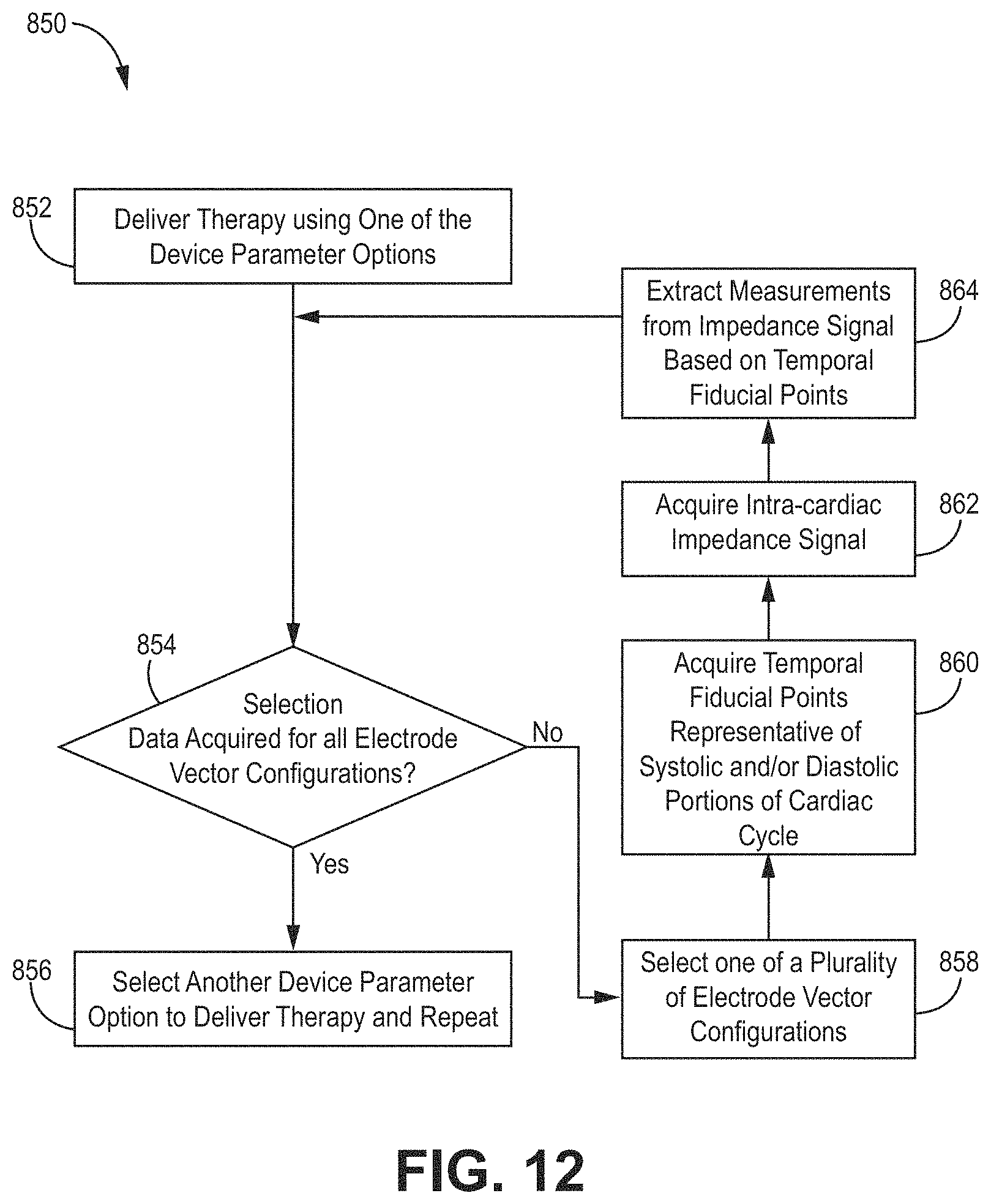
D00013

D00014

D00015

D00016

D00017
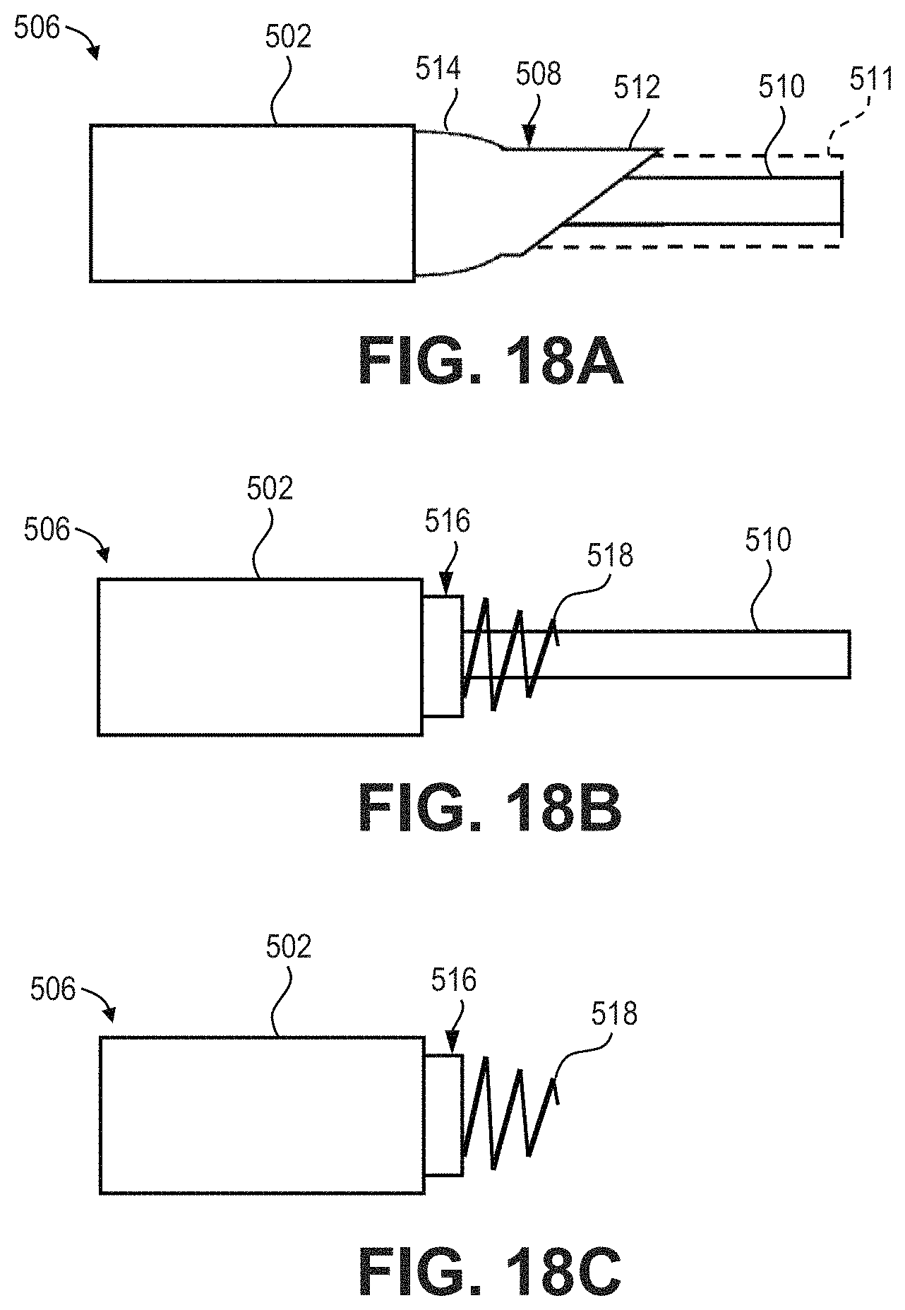
D00018

D00019

D00020
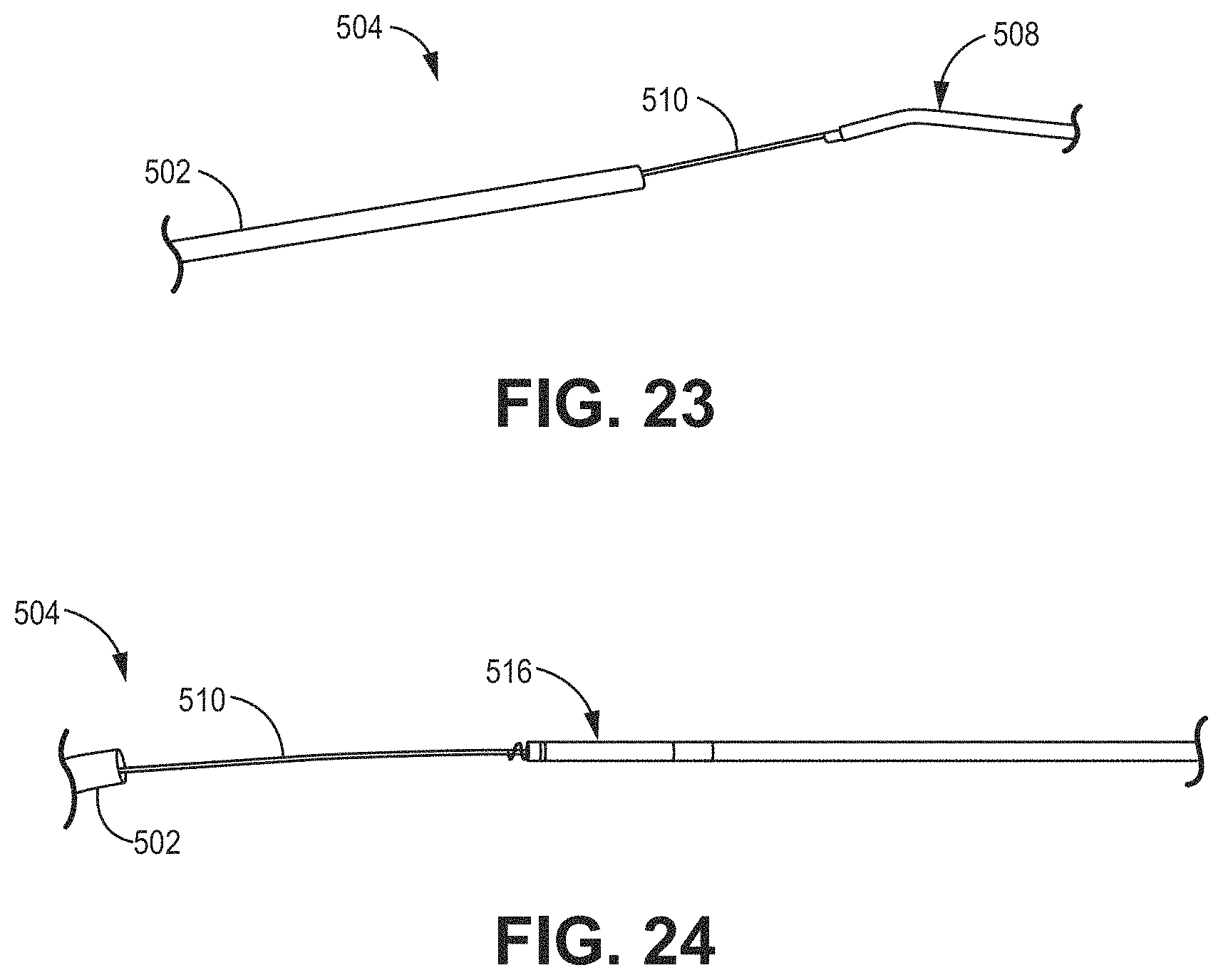
D00021
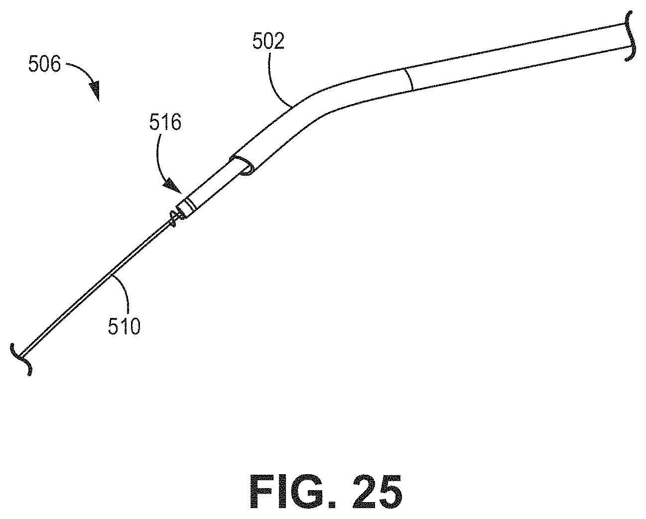
D00022

D00023
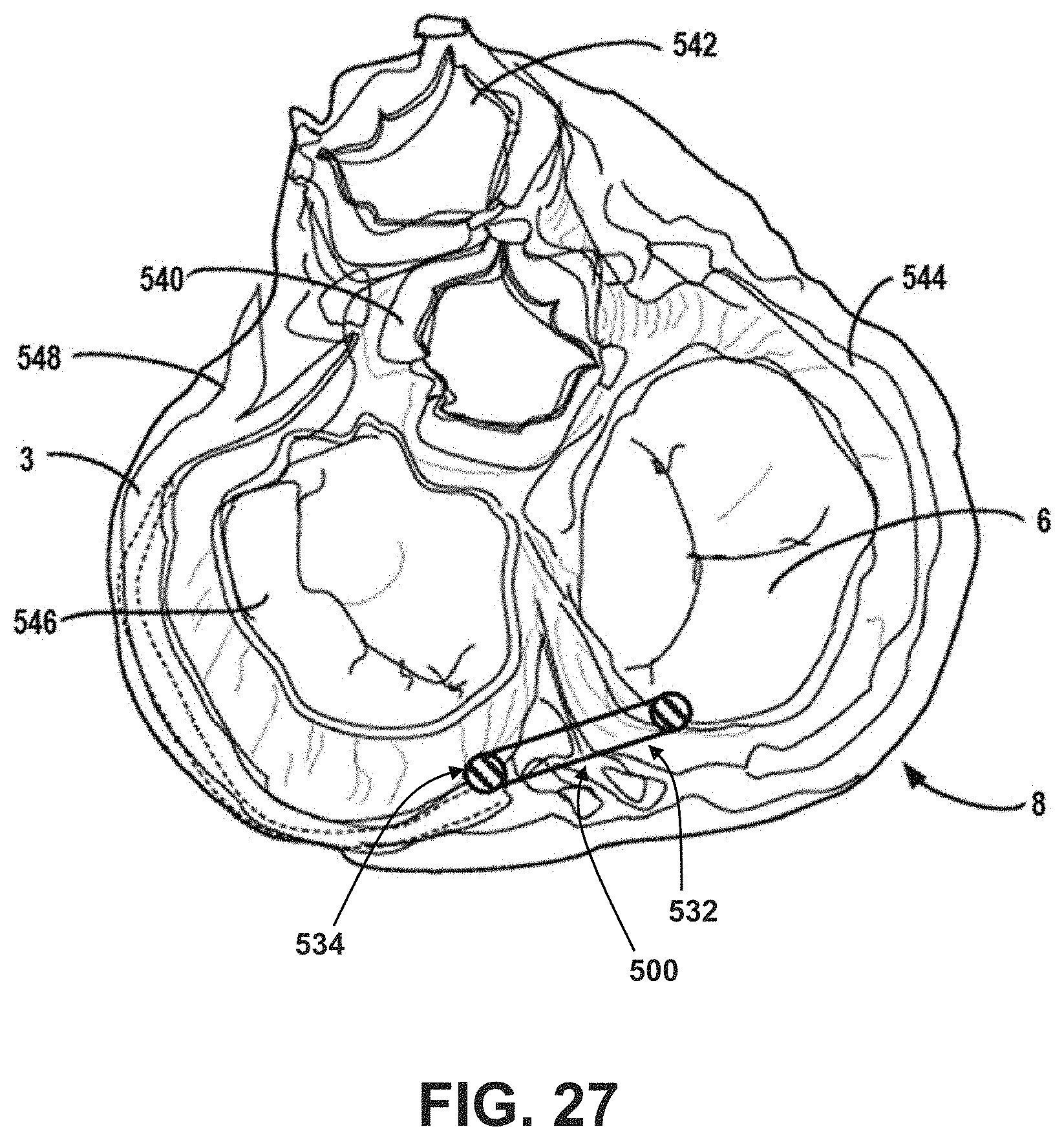
D00024

D00025

D00026

D00027

D00028

D00029

D00030
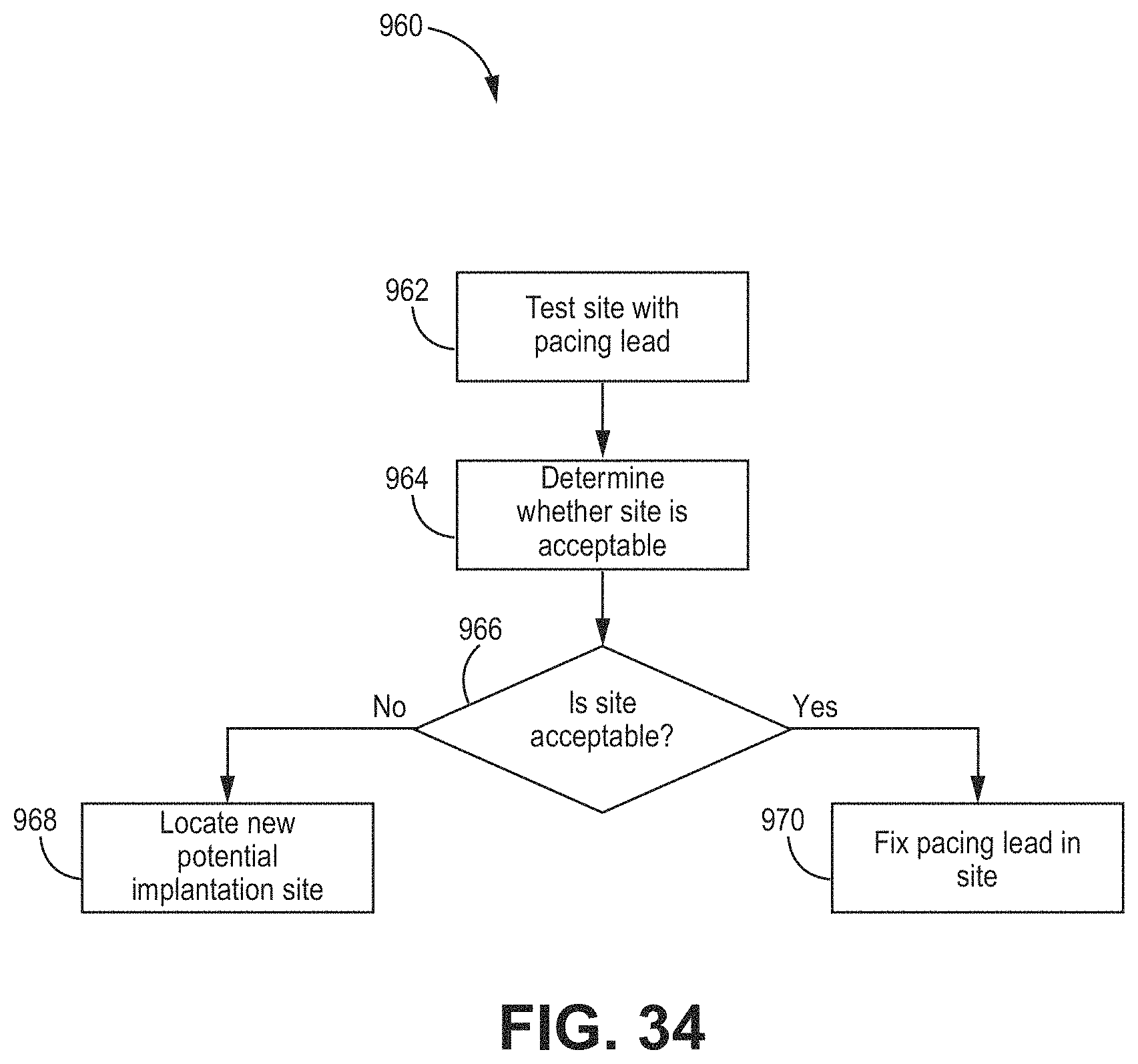
XML
uspto.report is an independent third-party trademark research tool that is not affiliated, endorsed, or sponsored by the United States Patent and Trademark Office (USPTO) or any other governmental organization. The information provided by uspto.report is based on publicly available data at the time of writing and is intended for informational purposes only.
While we strive to provide accurate and up-to-date information, we do not guarantee the accuracy, completeness, reliability, or suitability of the information displayed on this site. The use of this site is at your own risk. Any reliance you place on such information is therefore strictly at your own risk.
All official trademark data, including owner information, should be verified by visiting the official USPTO website at www.uspto.gov. This site is not intended to replace professional legal advice and should not be used as a substitute for consulting with a legal professional who is knowledgeable about trademark law.