Systems And Methods For Computer-aided Orthognathic Surgical Planning
Xia; James Jiong ; et al.
U.S. patent application number 16/326458 was filed with the patent office on 2020-06-25 for systems and methods for computer-aided orthognathic surgical planning. The applicant listed for this patent is THE METHODIST HOSPITAL SYSTEM. Invention is credited to Jaime Gateno, James Jiong Xia, Peng Yuan.
| Application Number | 20200197137 16/326458 |
| Document ID | / |
| Family ID | 61197154 |
| Filed Date | 2020-06-25 |


View All Diagrams
| United States Patent Application | 20200197137 |
| Kind Code | A1 |
| Xia; James Jiong ; et al. | June 25, 2020 |
SYSTEMS AND METHODS FOR COMPUTER-AIDED ORTHOGNATHIC SURGICAL PLANNING
Abstract
Systems and methods for orthognathic surgical planning are described herein. An example computer-implemented method can include generating a composite three-dimensional (3D) model of a subject's skull, defining a global reference frame for the composite 3D model, performing a cephalometric analysis on the composite 3D model to quantify at least one geometric property of the subject's skull, performing a virtual osteotomy to separate the composite 3D model into a plurality of segments, performing a surgical simulation using the osteotomized segments, and designing a surgical splint or template for the subject.
| Inventors: | Xia; James Jiong; (Houston, TX) ; Gateno; Jaime; (Bellaire, TX) ; Yuan; Peng; (Houston, TX) | ||||||||||
| Applicant: |
|
||||||||||
|---|---|---|---|---|---|---|---|---|---|---|---|
| Family ID: | 61197154 | ||||||||||
| Appl. No.: | 16/326458 | ||||||||||
| Filed: | August 21, 2017 | ||||||||||
| PCT Filed: | August 21, 2017 | ||||||||||
| PCT NO: | PCT/US2017/047805 | ||||||||||
| 371 Date: | February 19, 2019 |
Related U.S. Patent Documents
| Application Number | Filing Date | Patent Number | ||
|---|---|---|---|---|
| 62377084 | Aug 19, 2016 | |||
| Current U.S. Class: | 1/1 |
| Current CPC Class: | G06T 7/0014 20130101; G16H 20/40 20180101; G06T 2207/30204 20130101; A61C 13/0019 20130101; A61C 7/002 20130101; A61B 2034/107 20160201; A61B 2034/2068 20160201; A61C 13/0004 20130101; A61B 2034/102 20160201; A61B 2034/105 20160201; A61B 6/032 20130101; A61B 34/10 20160201; A61B 6/03 20130101; A61B 6/14 20130101; G06T 2207/30036 20130101; G16H 50/50 20180101; A61B 34/20 20160201 |
| International Class: | A61C 13/00 20060101 A61C013/00; A61B 34/10 20060101 A61B034/10; G06T 7/00 20060101 G06T007/00; A61B 34/20 20060101 A61B034/20 |
Goverment Interests
STATEMENT REGARDING FEDERALLY FUNDED RESEARCH
[0002] This invention was made with government support under Grant nos. RO1 DE022676 and RO1 DE021863 awarded by the National Institutes of Health/National Institute of Dental and Craniofacial Research. The government has certain rights in the invention.
Claims
1. A computer-implemented method for orthognathic surgical planning, comprising: generating a composite three-dimensional (3D) model of a subject's skull, wherein the composite 3D model includes a rendition of skeletal, dental, and soft tissue features of the subject's skull; defining a primal reference frame for the composite 3D model; performing a cephalometric analysis on the composite 3D model to quantify at least one geometric property of the subject's skull; performing a virtual osteotomy to separate the composite 3D model into a plurality of segments; performing a surgical simulation using the osteotomized segments; and designing a surgical splint or template for the subject.
2. The computer-implemented method of claim 1, wherein the composite 3D model comprises a plurality of 3D models, wherein the plurality of 3D models comprise two or more of a midface model, a mandible model, a soft tissue model, a dental model, or a fiducial marker model.
3. The computer-implemented method of claim 2, wherein generating the composite 3D model comprises merging the dental model with the midface and mandible models.
4. The computer-implemented method of claim 2, further comprising registering the plurality of 3D models that form the composite 3D model.
5. The computer-implemented method of claim 1, wherein defining the primal reference frame comprises reorienting the composite 3D model to a standard anatomical posture of the subject.
6. The computer-implemented method of claim 1, wherein defining the primal reference frame comprises calculating one or more planes of symmetry for the composite 3D model.
7. The computer-implemented method of claim 6, wherein the one or more planes of symmetry comprise a midsagittal plane, an axial plane, or a coronal plane.
8. The computer-implemented method of claim 1, wherein performing the cephalometric analysis comprises quantifying object symmetry of the subject's skull.
9. The computer-implemented method of claim 8, wherein performing the cephalometric analysis comprises quantifying object symmetry of the subject's skull using a weighted Procrustes analysis.
10. The computer-implemented method of claim 1, wherein performing the cephalometric analysis comprises quantifying symmetrical alignment between a feature of the subject's skull and the primal reference frame.
11. The computer-implemented method of claim 10, wherein quantifying symmetrical alignment between the feature of the subject's skull and the primal reference frame further comprises determining an object reference frame for the feature of the subject's skull.
12. The computer-implemented method of claim 11, wherein the feature of the subject's skull is a dental arch.
13. The computer-implemented method of claim 12, wherein determining the object reference frame further comprises using principal component analysis (PCA) based adaptive minimum Euclidean distances.
14. The computer-implemented method of claim 1, further comprising generating a cephalometric analysis report comprising the at least one geometric property of the subject's skull before and after the surgical simulation.
15. The computer-implemented method of claim 1, wherein the at least one geometric property comprises symmetry, shape, size, position, and/or orientation.
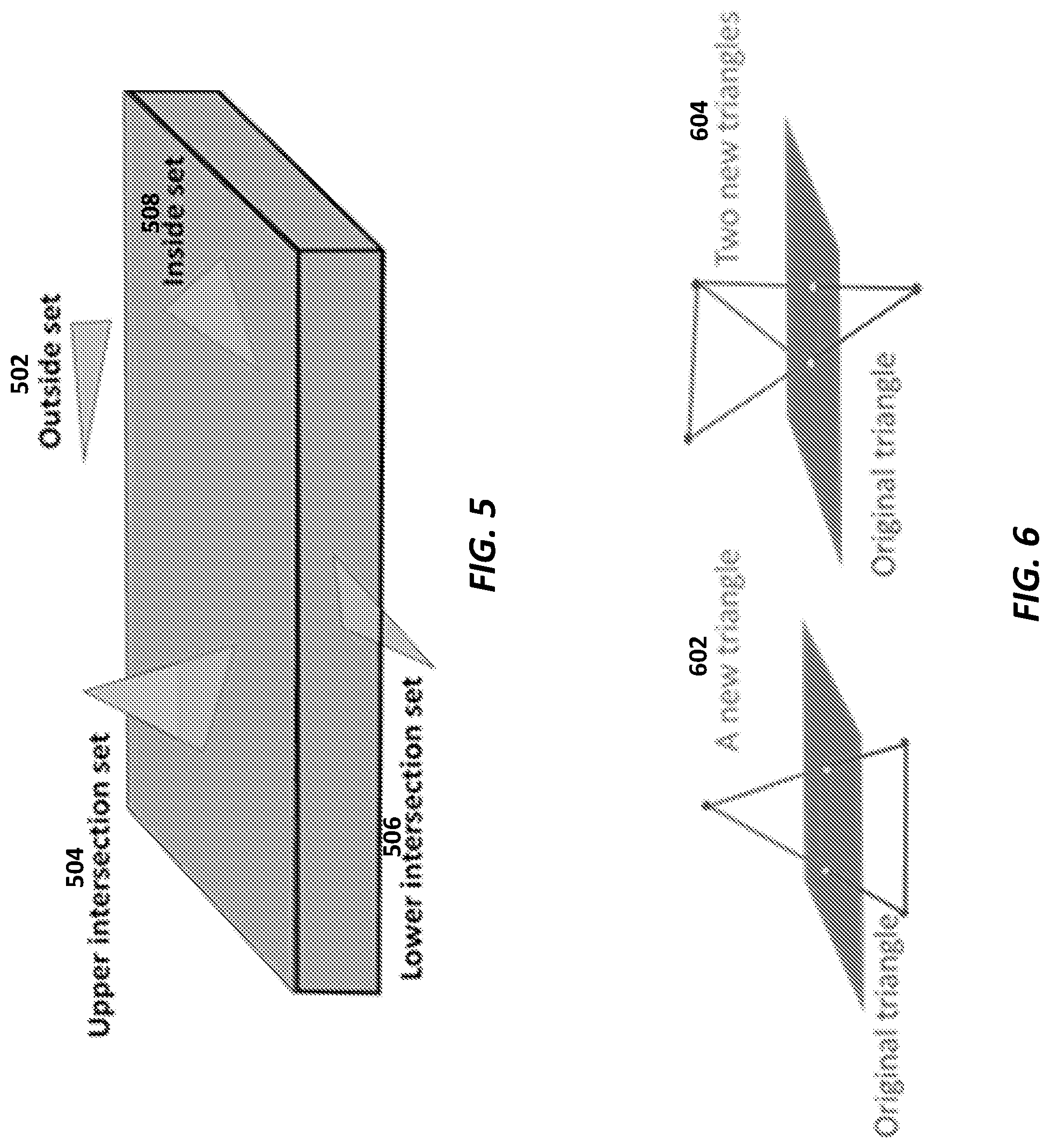
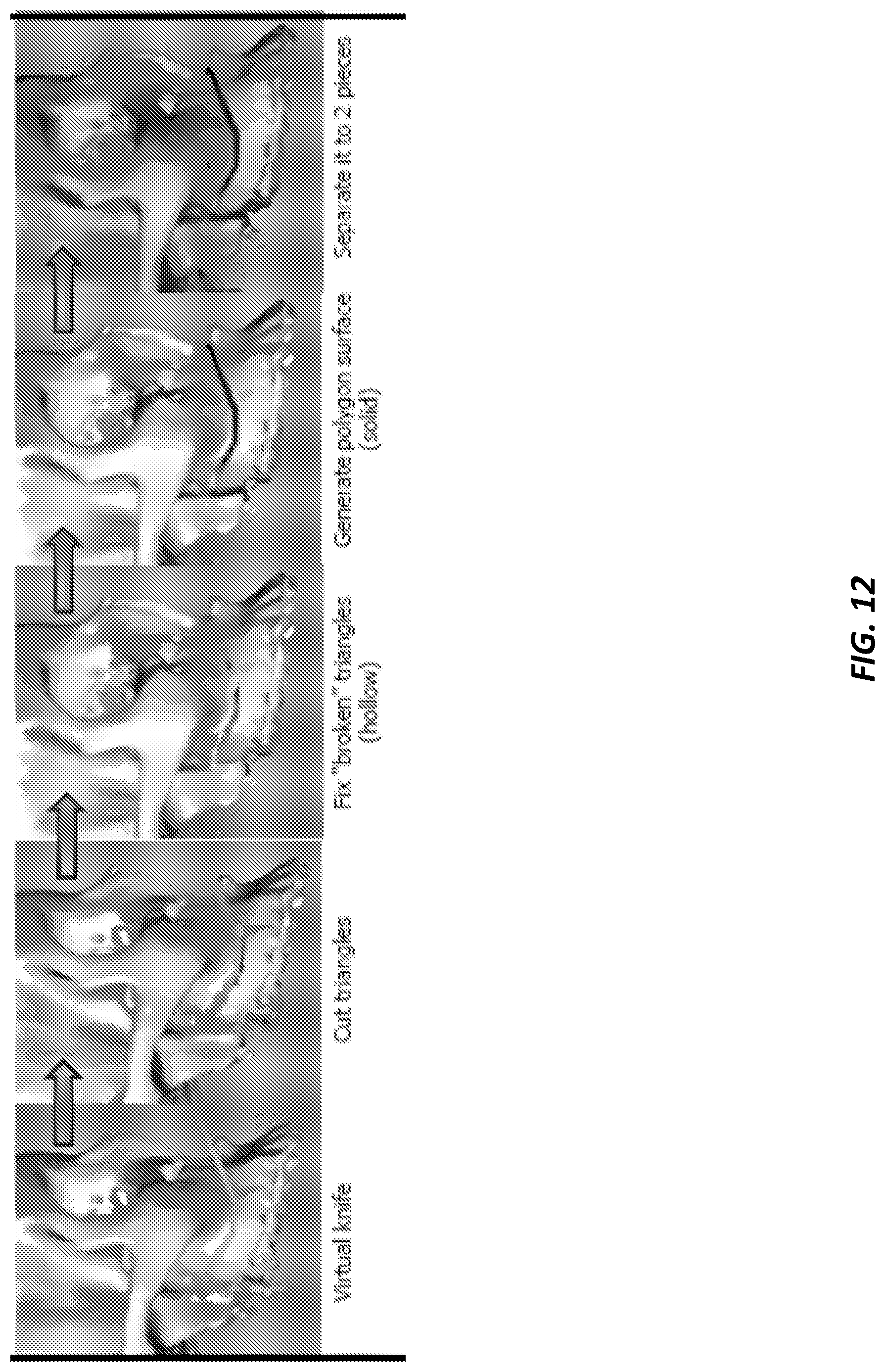
16. The computer-implemented method of claim 1, wherein the virtual osteotomy further comprises defining a group of multi-connected hexahedrons in proximity to a location of the virtual osteotomy and separating the composite 3D model into the plurality of segments.
17. The computer-implemented method of claim 16, wherein the plurality of segments comprise midface segment, Le Fort I segment and upper teeth, distal segment and lower teeth, chin segment, and/or left and right proximal segments.
18. The computer-implemented method of claim 1, wherein the surgical simulation comprises a maxillary surgery, a mandibular surgery, or a mandibular chin surgery.
19. The computer-implemented method of claim 1, wherein performing the surgical simulation comprises: defining a hierarchal structure for the osteotomized segments; establishing a final dental occlusion; and repositioning the osteotomized segments into a desired maxillomandibular combination.
20. The computer-implemented method of claim 19, wherein the final dental occlusion achieves a maximum intercuspation between the subject's upper and lower teeth.
21. The computer-implemented method of claim 19, wherein repositioning the osteotomized segments further comprises translating and/or rotating the maxillomandibular combination in six degrees of freedom.
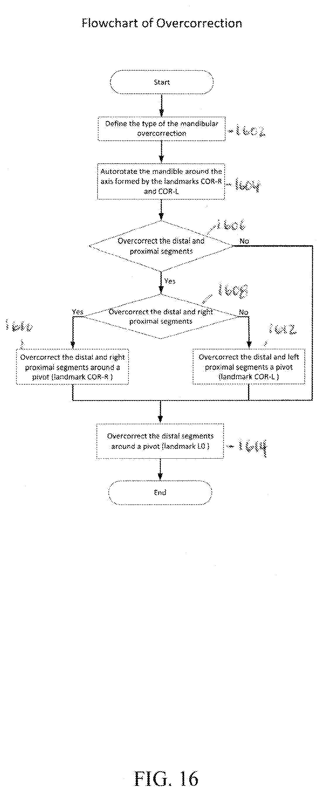
22. The computer-implemented method of claim 1, wherein the surgical simulation comprises performing an overcorrection by translating and/or rotating one or more of the osteotomized segments.
23. The computer-implemented method of claim 1, wherein the surgical splint or template is an intermediate splint for maxillary surgery with the subject's upper teeth in a desired position or for mandibular surgery with the subject's lower teeth in a desired position.
24. The computer-implemented method of claim 1, wherein the surgical splint or template is a final splint with the subject's upper and lower teeth in a desired position.
25. The computer-implemented method of claim 1, wherein designing the surgical splint or template further comprises: generating a 3D model of the surgical splint or template; and printing the surgical splint or template using a 3D printer.
26. The computer-implemented method of claim 1, further comprising displaying the composite 3D model on a display device.
27. The computer-implemented method of claim 1, further comprising assigning a respective unique identifier to each of a plurality of 3D objects.
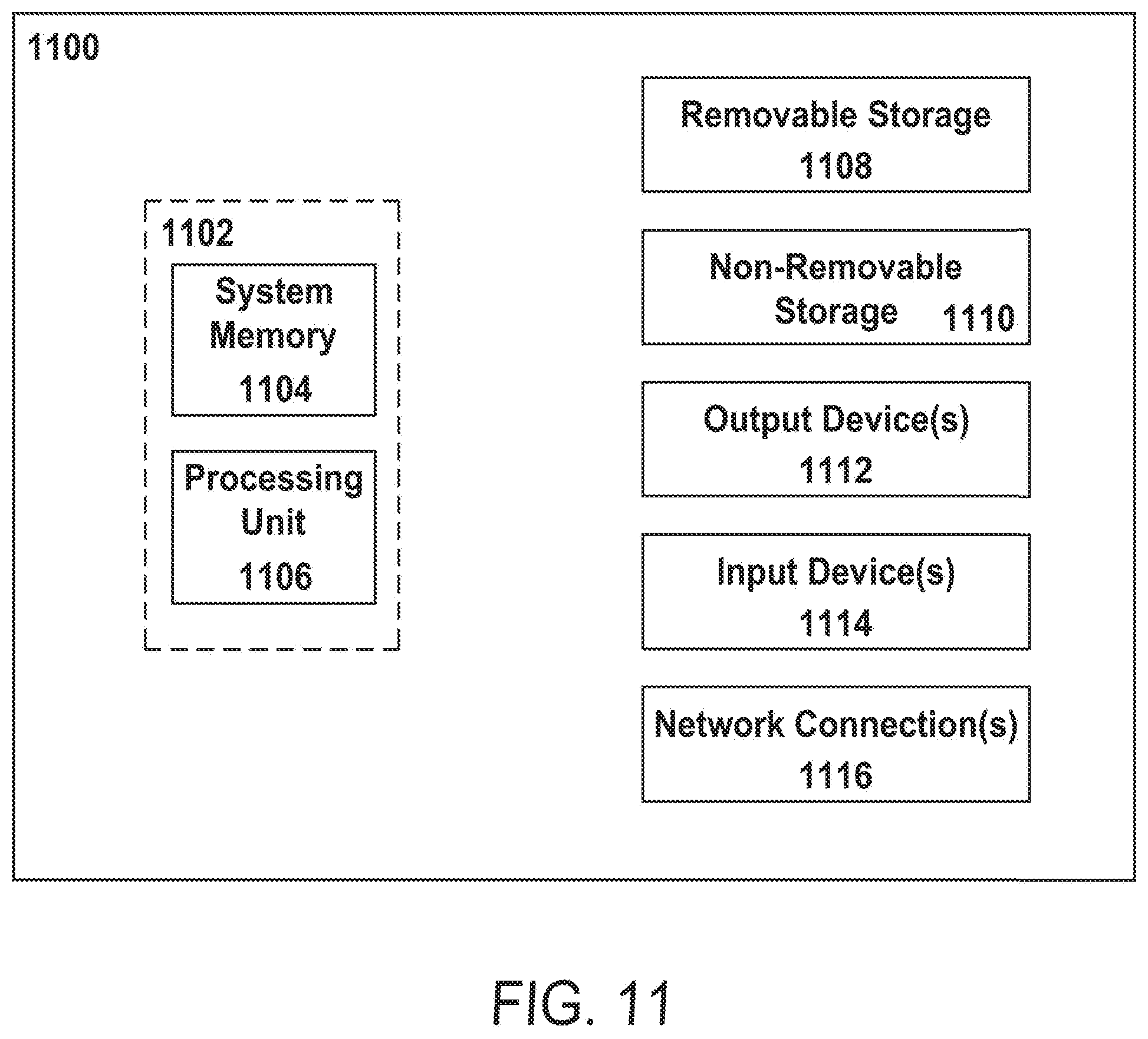
28. A system for orthognathic surgical planning, comprising: a processing unit; a memory in communication with the processing unit; a three-dimensional (3D) model module stored in the memory and configured to generate a composite 3D model of a subject's skull, wherein the composite 3D model includes a rendition of skeletal, dental, and soft tissue features of the subject's skull; a reference frame module stored in the memory and configured to define a primal reference frame for the composite 3D model; a 3D cephalometric analysis module stored in the memory and configured to quantify at least one geometric property of the subject's skull; a virtual osteotomy module stored in the memory and configured to separate the composite 3D model into a plurality of segments; a simulation module stored in the memory and configured to perform a surgical simulation using the osteotomized segments; and a surgical splint module stored in the memory and configured to design a surgical splint or template for the subject.
29-40. (canceled)
Description
CROSS-REFERENCE TO RELATED APPLICATIONS
[0001] This application claims the benefit of U.S. provisional patent application No. 62/377,084, filed on Aug. 19, 2016, and entitled "CEPHALOMETRY MODELING SYSTEM FOR SURGICAL PLANNING," the disclosure of which is expressly incorporated herein by reference in its entirety.
BACKGROUND
[0003] Orthognathic surgery is a surgical procedure to correct dentofacial, or jaw, deformities. Each year thousands of patients elect to undergo various orthognathic surgical procedures. However, due to the complex nature of the dentofacial anatomy, orthognathic surgery often requires extensive presurgical planning. Whereas surgical techniques have seen rapid improvement in the last 50 years, e.g. rigid fixation, resorbable materials, and distraction osteogenesis, available orthognathic surgical planning tools have remained unchanged since the 1960s, e.g. two-dimensional (2D) cephalometry, prediction tracing and stone dental model surgery [1-3]. There are many documented problems associated with these traditional techniques, which have often led to less than optimal surgical outcomes [3].
[0004] To address the problems associated with traditional planning methods as described above, a clinical protocol using a computer-aided surgical simulation (CASS) method for planning orthognathic surgery has been developed [3,4]. This CASS protocol has proven to be imperative in producing a more accurate and effective treatment plan [5,6]. It is now a new standard of care. However, CASS protocol requires that the user have extensive experience using computer graphics and virtual simulations. These simulations would have to be outsourced to expensive commercial services, or individual doctors would have to be trained extensively to use off-the-shelf computer graphics software. In addition, there is no known planning system available with the capabilities of performing every task required for implementing CASS protocol, e.g. neutral head posture (NHP) registration, three-dimensional (3D) cephalometric analysis, automated surgical simulation, and designing splint/template for 3D printers.
SUMMARY
[0005] An example computer-implemented method for orthognathic surgical planning is described herein. The computer-implemented method can include generating a composite three-dimensional (3D) model of a subject's skull, defining a primal reference frame for the composite 3D model, performing a cephalometric analysis on the composite 3D model to quantify at least one geometric property of the subject's skull, performing a virtual osteotomy to separate the composite 3D model into a plurality of segments, performing a surgical simulation using the osteotomized segments, and designing a surgical splint or template for the subject. The composite 3D model can include a rendition of skeletal, dental, and soft tissue features of the subject's skull.
[0006] Alternatively or additionally, the composite 3D model can include a plurality of 3D models. Additionally, the plurality of 3D models can include two or more of a midface model, a mandible model, a soft tissue model, a dental model, or a fiducial marker model. In some implementations, the step of generating the composite 3D model can include merging the dental model with the midface and mandible models. In some implementations, the computer-implemented method can further include registering the plurality of 3D models that form the composite 3D model.
[0007] Alternatively or additionally, the step of defining the primal reference frame can include reorienting the composite 3D model to a standard anatomical posture of the subject.
[0008] Alternatively or additionally, the step of defining the primal reference frame can include calculating one or more planes of symmetry for the composite 3D model. The one or more planes of symmetry can be a midsagittal plane, an axial plane, or a coronal plane.
[0009] Alternatively or additionally, the step of performing the cephalometric analysis can include quantifying object symmetry of the subject's skull. The cepha
D00000
D00001
D00002
D00003
D00004
D00005
D00006
D00007
D00008
D00009
D00010
D00011
D00012

D00013

D00014
D00015

D00016
D00017


XML
uspto.report is an independent third-party trademark research tool that is not affiliated, endorsed, or sponsored by the United States Patent and Trademark Office (USPTO) or any other governmental organization. The information provided by uspto.report is based on publicly available data at the time of writing and is intended for informational purposes only.
While we strive to provide accurate and up-to-date information, we do not guarantee the accuracy, completeness, reliability, or suitability of the information displayed on this site. The use of this site is at your own risk. Any reliance you place on such information is therefore strictly at your own risk.
All official trademark data, including owner information, should be verified by visiting the official USPTO website at www.uspto.gov. This site is not intended to replace professional legal advice and should not be used as a substitute for consulting with a legal professional who is knowledgeable about trademark law.