Miniaturized Mobile, Low Cost Optical Coherence Tomography System For Home Based Ophthalmic Applications
Scheibler; Lukas ; et al.
U.S. patent application number 16/805267 was filed with the patent office on 2020-06-25 for miniaturized mobile, low cost optical coherence tomography system for home based ophthalmic applications. This patent application is currently assigned to ACUCELA INC.. The applicant listed for this patent is ACUCELA INC.. Invention is credited to Ryo Kubota, Matthias Pfister, Lukas Scheibler, Urban Schnell, Stefan Troller.
| Application Number | 20200196858 16/805267 |
| Document ID | / |
| Family ID | 62627807 |
| Filed Date | 2020-06-25 |


View All Diagrams
| United States Patent Application | 20200196858 |
| Kind Code | A1 |
| Scheibler; Lukas ; et al. | June 25, 2020 |
MINIATURIZED MOBILE, LOW COST OPTICAL COHERENCE TOMOGRAPHY SYSTEM FOR HOME BASED OPHTHALMIC APPLICATIONS
Abstract
Improved optical coherence tomography systems and methods to measure thickness of the retina are presented. The systems may be compact, handheld, provide in-home monitoring, allow the patient to measure himself or herself, and be robust enough to be dropped while still measuring the retina reliably.
| Inventors: | Scheibler; Lukas; (Telluride, CO) ; Pfister; Matthias; (Liebefeld-Bern, CH) ; Schnell; Urban; (Munchenbuchsee, CH) ; Troller; Stefan; (Sissach, CH) ; Kubota; Ryo; (Seattle, WA) | ||||||||||
| Applicant: |
|
||||||||||
|---|---|---|---|---|---|---|---|---|---|---|---|
| Assignee: | ACUCELA INC. Seattle WA |
||||||||||
| Family ID: | 62627807 | ||||||||||
| Appl. No.: | 16/805267 | ||||||||||
| Filed: | February 28, 2020 |
Related U.S. Patent Documents
| Application Number | Filing Date | Patent Number | ||
|---|---|---|---|---|
| 15996329 | Jun 1, 2018 | 10610096 | ||
| 16805267 | ||||
| PCT/US17/67603 | Dec 20, 2017 | |||
| 15996329 | ||||
| 62547314 | Aug 18, 2017 | |||
| 62546935 | Aug 17, 2017 | |||
| 62539382 | Jul 31, 2017 | |||
| 62437486 | Dec 21, 2016 | |||
| Current U.S. Class: | 1/1 |
| Current CPC Class: | A61B 2560/0456 20130101; A61B 2560/0425 20130101; A61B 2560/0431 20130101; A61B 3/0008 20130101; A61B 3/102 20130101; A61B 5/0013 20130101; A61B 3/1225 20130101; A61B 3/0025 20130101; A61B 2505/07 20130101; A61B 3/10 20130101; G01B 9/02 20130101; A61B 2576/00 20130101; A61B 3/1005 20130101 |
| International Class: | A61B 3/10 20060101 A61B003/10; A61B 3/00 20060101 A61B003/00; A61B 3/12 20060101 A61B003/12; A61B 5/00 20060101 A61B005/00; G01B 9/02 20060101 G01B009/02 |
Claims
1. A compact optical coherence tomography (OCT) system to measure a thickness of a retina, the compact OCT system comprising: a detector; a light source configured to generate a light beam comprising a plurality of wavelengths; a plurality of optical elements coupled to the light source to direct the beam into the eye and generate an interference signal at the detector; and circuitry coupled to the detector and the light source to determine the retinal thickness in response to the signal; wherein the light source comprises a first VCSEL and a second VCSEL and the light beam comprises light from the first VSCEL and the second VSCEL.
2. The compact OCT system of claim 1, wherein a repeatability between successive measurements of the retina is within 25 .mu.m and a reproducibility between measurements over a longer time of at least a week is within 25 .mu.m and optionally wherein the reproducibility is measured with a test object.
3. The compact OCT system of claim 2, wherein the compact OCT system is configured to determine a change in the thickness when two measurements of the thickness produce two thickness values that differ by more than 50 .mu.m.
4. The compact OCT system of claim 2, wherein the repeatability is based on measurements performed within one minute and determined with a confidence interval of 95%.
5. The compact OCT system of claim 2, wherein the reproducibility is within 25 .mu.m, wherein the reproducibility indicates a variation in measurements taken by a single person on the retina, under a set of conditions, and within a predetermined period of time.
6. The compact OCT system of claim 5, wherein the predetermined period of time is at least two months.
7. The compact OCT system of claim 5, further comprising a test fixture that provides a test material having a plurality of reflecting surfaces.
8. The compact OCT system of claim 1, wherein the compact OCT system is configured to perform measurements at a frequency within a range defined by any two of the following: about 0.1 s (10 Hz), 0.02 s, (50 Hz), 0.01 s (100 Hz), and 0.002 (500 Hz).
9. The compact OCT system of claim 1, wherein the light source, the plurality of optical elements, the detector, and the circuitry are configured to be held in front of the eye with the detector no more than about 200 mm from the eye.
10. The compact OCT system of claim 1, wherein the circuitry is configured to drive the first VCSEL and the second VSCEL above a maximum of a rated wavelength range for each of a plurality of measurements and to delay a first measurement from a second measurement by an amount within a range from about 1 milliseconds ("ms") to about 100 milliseconds in order to inhibit overheating of the first VSCEL and the second VCSEL.
11. The compact OCT system of claim 1, wherein the circuitry is configured to drive the first VSCEL and the second VCSEL above the maximum of the rated wavelength range with a drive current having a waveform, the waveform having a first portion above a maximum rated current of the first VSCEL and the second VCSEL and a second portion below the maximum rated current and wherein the first portion comprises no more than about 50 percent of a duration of the waveform in order to inhibit overheating of the VSCEL.
12. The compact OCT system of claim 1, wherein the circuitry is configured to cause an emitted wavelength to sweep over a range of wavelengths with a sweeping frequency and the circuitry is configured to determine the thickness in response to frequencies of the interference signal.
13. The compact OCT system of claim 1, wherein the sweeping frequency is within a range from about 50 Hz to about 10 KHz, and optionally within a range from about 100 Hz to about 5 kHz, or from about 1 kHz to about 5 KHz.
14. The compact OCT system of claim 1, wherein the plurality of optical elements is arranged to provide a reference optical path and a measurement optical path and the interference signal results from interference of light from the reference optical path and light from the measurement optical path.
15. The compact OCT system of claim 1, wherein the circuitry is configured to drive the first VCSEL and the second VCSEL in sequence with similar sweep frequencies in order to sweep first wavelengths of light from the first VSCEL and second wavelengths of light the second VSCEL with similar rates and optionally wherein the similar sweep frequencies and the similar rates of the first VSCEL and the second VSCEL are within 5% of each other and optionally within 1% of each other.
16. The compact OCT system of claim 1, wherein the circuitry is configured to have the first VSCEL on when the second VSCEL is off and have the second VSCEL on when the first VSCEL is off and to inhibit temporal overlap of light from the first VSCEL and the second VCEL and wherein the second VSCEL is configured to turn on and emit light having wavelengths within about 0.1 nm of light from the first VSCEL when the first VSCEL is turned off.
17. The compact OCT system of claim 1, further comprising housing to support the light source, the optical elements, the detector, and the circuitry, and wherein the housing is configured to be held in a hand of a user in front of the eye in order to direct the light beam into the eye.
18. The compact OCT system of claim 1, further comprising an occlusion structure to occlude one eye while the other eye is measured, the occlusion structure coupled to the housing and the sensor to determine which eye is measured.
19. The compact OCT system of claim 1, wherein the housing comprises a body and a lid rotatably attached to the body, wherein when in an open position, the lid is configured to rotate around the body.
20. The compact OCT system of claim 1, further comprising a battery, wherein the battery is located further away from the detector than the light source.
21. The compact OCT system of claim 20, further comprising a docking station to receive the housing and charge the battery contained within the housing to power the light source and the circuitry, the docking station comprising wireless communication circuitry to transmit the thickness to a remote server and optionally wherein the wireless communication circuitry comprises a Global System for Mobile Communications (GSM), third generation (3G), or fourth generation (4G) module.
22. The compact OCT system of claim 1, wherein the circuitry is configured to receive or transmit data through a communication network.
23. The compact OCT system of claim 1, wherein the communication network includes the Internet, a cellular network, or a short-range communication network.
Description
CROSS REFERENCE TO RELATED APPLICATIONS
[0001] This application is a divisional of U.S. patent application Ser. No. 15/996,329, filed Jun. 1, 2018, which is a continuation of International Application No. PCT/US17/67603, entitled "Miniaturized Mobile, Low Cost Optical Coherence Tomography System for Home Based Ophthalmic Applications," filed Dec. 20, 2017; and claims the benefit under 35 U.S.C. .sctn. 119(e) of U.S. Provisional Application No. 62/437,486, entitled "Miniaturized Mobile, Low Cost Optical Coherence Tomography System for Home Based Ophthalmic Applications," filed Dec. 21, 2016; U.S. Provisional Application No. 62/539,382, entitled "Miniaturized Mobile, Low Cost Optical Coherence Tomography System for Home Based Ophthalmic Applications," filed Jul. 31, 2017; U.S. Provisional Application No. 62/546,935, entitled "Miniaturized Mobile, Low Cost Optical Coherence Tomography System for Home Based Ophthalmic Applications," filed Aug. 17, 2017; and U.S. Provisional Application No. 62/547,314, entitled "Miniaturized Mobile, Low Cost Optical Coherence Tomography System for Home Based Ophthalmic Applications," filed Aug. 18, 2017, the disclosures of which are incorporated, in their entirety, by this reference.
BACKGROUND
[0002] The eye is critical for vision, and people need to see. The eye has a cornea and lens that refract light and form an image on the retina. The retina generates electrical signals in response to the image formed thereon, and these electrical signals are transmitted to the brain via the optic nerve. The fovea and macula of the retina have an increased density of cones in relation to other areas of the retina and provide crisp, sharp vision. Unfortunately, diseases of the retina can adversely affect vision even though other parts of the eye, such as the cornea and lens are healthy.
[0003] Retinal thickness can be used to diagnose and monitor the health of the retina. Many patients who have been diagnosed with retinal vascular diseases and other diseases or conditions have an elevated retinal thickness and take or are treated with medications. Macular edema is an example of elevated retinal thickness which is often related to other diseases such as diabetes. Macular edema can be related to other diseases such as age related macular degeneration, uveitis, blockage of retinal vasculature, and glaucoma, for example. It would be helpful to know quickly if a medication is not working or requires re-administration so that treatment can be modified accordingly and vision preserved. One approach used to measure the thickness of the retina is optical coherence tomography (OCT).
[0004] Unfortunately, many prior OCT systems are overly complex and expensive and not well-suited to monitoring retinal thickness regularly, such as on a weekly or daily basis. The prior standard of eye care involves a visit to a health care provider who measures retinal thickness, but such visits require scheduling and appointments and can become expensive, especially if conducted on a weekly or daily basis. Many of the prior OCT systems are not well-suited for in-home monitoring or mobile health care. Such prior systems typically weigh more than a person can easily carry and are not-well suited to travel with the patient. In addition, the prior OCT systems are more complex than would be ideal, and not well-suited for everyday use and hazards such as being dropped. The prior cost of an OCT system may exceed what a typical patient can afford. Furthermore, use of a prior OCT system may require a trained operator. For the above reasons, in-home monitoring of retinal thickness has not been adopted as the prior standard of care and prior care of patients with retinal disease can be less than ideal in many instances.
[0005] In light of the above, it would be helpful to have improved OCT systems and methods to measure thickness of the retina. Ideally, such systems would be compact, handheld, provide in-home monitoring, allow the patient to measure himself or herself, and be robust enough to be dropped while still measuring the retina reliably.
SUMMARY
[0006] The compact optical coherence tomography (OCT) system and methods disclosed herein allow in-home and mobile monitoring of retinal thickness. Although specific reference is made to measuring retinal thickness, the compact OCT system and methods disclosed herein will find application in many fields, such as microscopy, metrology, aerospace, astronomy, telecommunications, medicine, pharmaceuticals, dermatology, dentistry, and cardiology.
[0007] The compact OCT system comprises a plurality of components arranged to provide a decreased optical path and weight. In many embodiments, the compact OCT system is configured to measure changes in retinal thickness that are less than a resolution value of the OCT system, which allows the size, cost and complexity to be decreased significantly. The system comprises sufficient repeatability and reproducibility to accurately detect changes in retinal thickness smaller than the system axial resolution value. The compact OCT system is capable of scanning the wavelength range and acquiring OCT data with sufficient speed in order to decrease errors associated with movement of the system in relation to the eye. In many embodiments, the compact OCT system is calibrated for a specific patient with a clinical reference system having a higher resolution than the compact OCT system, and the compact OCT system is calibrated to the specific patient based on the retinal thickness measured with the clinical reference system. In some cases, the compact OCT system comprises a calibration kit or fixture, which allows the system to be tested to ensure that the repeatability and reproducibility remain within acceptable tolerances.
[0008] In some instances, the compact OCT system is configured to be held in the hand of user for the patient to measure himself or herself. Alternatively, the compact OCT system may be configured to be mounted to a table stand or to the head of the user. In some embodiments, the compact OCT system comprises a visible target for the patient to align himself or herself with the compact spectrometer while the patient holds the measurement components of the system with his hand. The compact OCT system comprises a housing to contain the measurement components, and the housing is sized, in some instances, such that the user can readily grasp the housing and lift the measurement components within the housing and align the OCT system with his eye. The compactness and decreased mass of the OCT system allows the system to be easily held in the hand of the patient and transported with the patient. In many embodiments, the tomography system comprises a maximum dimension across within a range from about 80 mm to about 160 mm, and a mass within a range from about 100 grams to about 500 grams. In many embodiments, the OCT system is configured without internal moving parts in order to increase the reliability of the system. The compact OCT system is optionally configured to be dropped from a distance of about one foot, and provide a change in measurement repeatability and accuracy of retinal thickness of no more than about 25 .mu.m, for example.
[0009] In some embodiments, the compact OCT system comprises a light source configured to emit a plurality of wavelengths, a detector, optical elements arranged to generate an optical interference signal on the detector, and circuitry coupled to the detector and light source. In some embodiments, the light source comprises a light source configured to emit a light beam of varying wavelength in order to sweep the wavelength over a range of wavelengths. In some instances, the wavelengths are swept over a range from about 3 nm to 10 nm in order to measure the thickness of the retina. This range can provide decreased system complexity and cost with sufficient axial resolution, repeatability, and reproducibility to determine changes in retinal thickness by 25 .mu.m or less, although longer wavelength sweeps can be used. In some embodiments, the sweeping range of the OCT system within a range from 3 nm to 10 nm allows detection of retinal thickness larger than about 150 .mu.m and changes in retinal thickness as small as 25 .mu.m, for example, with the compact OCT system, although longer wavelength sweeps can be used. The circuitry is configured, in some embodiments, to drive the light source with a waveform having a characteristic period and sweeping frequency, such as a saw tooth waveform. In some instances, the circuitry is coupled to the detector to measure frequencies of an interference signal from the light returned from eye to determine retinal thickness of the eye, although the thickness of other objects can be measured. In some embodiments, the circuitry is configured to drive the light source over a maximum rated current threshold for a portion of the waveform and below the maximum rated current threshold for another portion of the waveform, in which the light source emits light during both portions of the waveform. This overdriving of the light source within a portion of the waveform allows for an extended wavelength range of the light source and increased measurement range with decreased complexity, size, and weight of the OCT system.
INCORPORATION BY REFERENCE
[0010] All publications, patents, and patent applications mentioned in this specification are herein incorporated by reference to the same extent as if each individual publication, patent, or patent application was specifically and individually indicated to be incorporated by reference.
BRIEF DESCRIPTION OF THE DRAWINGS
[0011] The novel features of the invention are set forth with particularity in the appended claims. A better understanding of the features and advantages of the present invention will be obtained by reference to the following detailed description that sets forth illustrative embodiments, in which the principles of the invention are utilized, and the accompanying drawings of which:
[0012] FIG. 1 shows a simplified diagram of the human eye.
[0013] FIG. 2 shows a schematic of a system allowing a patient to measure retinal thickness (RT) at multiple time points and to communicate the results, in accordance with some embodiments.
[0014] FIG. 3A shows a handheld optical coherence tomography (OCT) device utilizing Bluetooth communication, in accordance with some embodiments.
[0015] FIG. 3B shows a handheld OCT device utilizing the Global System for Mobile Communications (GSM), in accordance with some embodiments.
[0016] FIG. 4 shows a diagram of the flow of information in the handheld OCT system, in accordance with some embodiments.
[0017] FIG. 5 shows a schematic for a swept source optical coherence tomography (SS-OCT) device, in accordance with some embodiments.
[0018] FIG. 6A shows a schematic for a SS-OCT device lacking a reference mirror, in accordance with some embodiments.
[0019] FIG. 6B shows the wavelength range over which the vertical cavity surface emitting laser (VCSEL) operates in the SS-OCT device lacking a reference mirror, in accordance with some embodiments.
[0020] FIG. 7A shows a schematic for a SS-OCT device utilizing an external cavity, in accordance with some embodiments.
[0021] FIG. 7B shows the wavelength range over which the VCSEL operates in the SS-OCT device lacking a reference mirror, in accordance with some embodiments.
[0022] FIG. 7C shows how the use of an external cavity mirror may shift the OCT peaks to a higher optical frequency compared to the frequency of the OCT peak in the absence of the external cavity mirror.
[0023] FIG. 8A shows a schematic for a SS-OCT device utilizing two VCSELs and lacking a reference mirror at a first particular point in time, in accordance with some embodiments.
[0024] FIG. 8B shows a schematic for a SS-OCT device utilizing two VCSELs and lacking a reference mirror at second particular point in time, in accordance with some embodiments.
[0025] FIG. 8C shows the wavelength range over which the VCSELs operate in the SS-OCT device utilizing two VCSELs and lacking a reference mirror, in accordance with some embodiments.
[0026] FIG. 9 shows the operation of a VCSEL beyond its maximum current rating, in accordance with some embodiments.
[0027] FIG. 10A shows a graphical representation of axial resolution.
[0028] FIG. 10B shows a graphical representation of repeatability and reproducibility.
[0029] FIG. 10C shows a graphical representation of the repeatability and reproducibility associated with measurements of the RT of a retina that has not exhibited a change in RT.
[0030] FIG. 10D shows a graphical representation of the repeatability and reproducibility associated with measurements of the RT of a retina that has exhibited a change in RT.
[0031] FIG. 11 is a flowchart of a method for conducting repeated measurements of a patient's RT over time and noting changes that may correspond to adverse outcomes.
[0032] FIG. 12 shows a flowchart of a method for determining the RT from a measurement using the handheld OCT device.
[0033] FIG. 13 shows an exemplary digital processing device programmed or otherwise configured to determine a RT or RLT.
[0034] FIG. 14 shows an optical setup for determining the limit of detection of an SS-OCT system utilizing a single VCSEL and no reference arm.
[0035] FIG. 15 shows oscilloscope signals at two different points in time for a VCSEL driven out of its rated operating range.
[0036] FIG. 16 shows oscilloscope signals for two different configurations of the optical setup.
[0037] FIG. 17 shows a method of signal processing for extracting the frequency of oscillation of the interference signal generated using an SS-OCT system utilizing a single VCSEL and no reference arm.
[0038] FIG. 18 shows the results of a study to determine the reproducibility of extracting the frequency of oscillation of the interference signal generated using an SS-OCT system utilizing a single VCSEL and no reference arm.
[0039] FIG. 19 shows the means and 95% confidence intervals of the frequencies obtained during the study to determine the reproducibility of extracting the frequency of oscillation of the interference signal generated using an SS-OCT system utilizing a single VCSEL and no reference arm.
[0040] FIG. 20A shows a diagram of a handheld OCT system with an eye adapter.
[0041] FIG. 20B shows a handheld OCT system adapted to measure a right eye or a left eye.
[0042] FIG. 20C shows a handheld OCT system with indicator lights and communications adapters.
[0043] FIG. 20D shows a handheld OCT placed proximate to an eye to provide an OCT measurement.
[0044] FIG. 21 shows a calibration kit for a handheld OCT device.
[0045] FIG. 22 shows a schematic for a SS-OCT device utilizing a scanning mechanism, in accordance with some embodiments;
[0046] FIG. 23A shows a schematic for a scanning mechanism, in accordance with some embodiments;
[0047] FIG. 23B shows an array of retinal layer thickness measurement sites, in accordance with some embodiments;
[0048] FIG. 24 shows a schematic for a SS-OCT device utilizing a scanning mechanism and one or more cameras, in accordance with some embodiments;
[0049] FIG. 25 shows a method for extracting a measurement of a retinal thickness (RT) or retinal layer thickness (RLT) from an OCT measurement, in accordance with some embodiments;
[0050] FIG. 26 shows a schematic for a SS-OCT device incorporating a visual function measurement apparatus, in accordance with some embodiments;
[0051] FIG. 27A and FIG. 27B show visual cues on a background, in accordance with some embodiments;
[0052] FIG. 28A and FIG. 28B show a configuration for a handheld monocular OCT system, in accordance with some embodiments;
[0053] FIG. 29A, FIG. 29B, and FIG. 29C show a configuration for an exemplary handheld binocular OCT system, in accordance with some embodiments;
[0054] FIG. 30 shows a configuration for an exemplary handheld binocular OCT system, in accordance with some embodiments;
[0055] FIG. 31A shows a handheld binocular OCT system oriented to measure a subject's left eye, in accordance with some embodiments;
[0056] FIG. 31B shows a housing for an exemplary handheld binocular OCT system oriented to measure a subject's right eye, in accordance with some embodiments;
[0057] FIG. 32A shows a VCSEL coupled to a cooler to increase the range of wavelengths swept, in accordance with some embodiments;
[0058] FIG. 32B shows a schematic of a VCSEL coupled to a thermoelectric cooler, in accordance with some embodiments;
[0059] FIG. 33A shows a compact SS-OCT system placed on a support, in accordance with some embodiments
[0060] FIG. 33B shows a user using the compact SS-OCT device mounted on a support, in accordance with some embodiments;
[0061] FIG. 34 shows a schematic for the optics of a SS-OCT device incorporating a visual fixation target apparatus and a fundus imaging apparatus, in accordance with some embodiments;
[0062] FIG. 35 shows a schematic of an electronic circuit board for controlling the optics of the compact SS-OCT systems described herein, in accordance with some embodiments;
[0063] FIG. 36 shows a schematic for the optics of a SS-OCT device incorporating an interferometer for enhancing phase stability;
[0064] FIG. 37A, FIG. 37B, and FIG. 37C show exemplary fundus images obtained using the systems and methods described herein;
[0065] FIG. 38A, and FIG. 38B show the effects of re-sampling for chirp correction of a SS-OCT signal in the time domain;
[0066] FIG. 39A, FIG. 39B, and FIG. 39C show the frequency drift of uncorrected and chirp corrected SS-OCT signals in the frequency domain;
[0067] FIG. 40A, FIG. 40B, and FIG. 40C show exemplary phase drifts of uncorrected SS-OCT signals associated with a variety of sources of noise;
[0068] FIG. 41A, FIG. 41B, FIG. 41C, and FIG. 41D show simulations of phase shifts associated with patient movement;
[0069] FIG. 42A, FIG. 42B, FIG. 42C, and FIG. 42D show simulations of the effect of A-scan time on the error arising from phase shifts associated with patient movement; and
[0070] FIG. 43A, and FIG. 43B show the amplitude of typical patient movements.
DETAILED DESCRIPTION
[0071] While various embodiments of the invention have been shown and described herein, it will be obvious to those skilled in the art that such embodiments are provided by way of example only. Numerous variations, changes, and substitutions may occur to those skilled in the art without departing from the invention. It should be understood that various alternatives to the embodiments of the invention described herein may be employed.
[0072] The compact OCT system disclosed herein is well-suited for use with many prior clinical tests, such as retinal thickness measurements. In some cases, the OCT system is used by the patient, or by a health care provider. In many instances the patient can align himself with the system, although another user can align the patient with the system and take the measurement. In some embodiments, the OCT system is integrated with prior software and systems to provide additional information to healthcare providers, and can provide alerts in response to changes in retinal thickness. The alerts are optionally sent to the patient, caregiver, and health care providers when corrective action should be taken such as a change in medication, dosage, or a reminder to take medication.
[0073] As used herein, the term "retinal thickness (RT)" refers to a thickness of the retina between layers used to evaluate the thickness of a retina of a patient. The RT may correspond to a thickness of the retina between an anterior surface of the retina and external limiting membrane, for example.
[0074] As used herein, the term "retinal layer thickness (RLT)" refers to the thickness of one or more optically detectable layers of the retina. The optically detectable layers of the retina may comprise a thickness of the retina extending between the external limiting membrane and the retinal pigment epithelium, for example.
[0075] As used herein, the term "high resolution" refers to a measurement system capable of optically resolving structures that are smaller in at least one linear dimension than structures that can be a resolved by a measurement system of lower resolution.
[0076] FIG. 1 shows a simplified diagram of the human eye. Light enters the eye through the cornea 10. The iris 20 controls the amount of light allowed to pass by varying the size of the pupil 25 that allows light to proceed to the lens 30. The anterior chamber 40 contains aqueous humor 45 which determines the intraocular pressure (TOP). The lens 30 focuses light for imaging. The focal properties of the lens are controlled by muscles which reshape the lens. Focused light passes through the vitreous chamber 50, which is filled with vitreous humor 55. The vitreous humor maintains the overall shape and structure of the eye. Light then falls upon the retina 60, which has photosensitive regions. In particular, the macula 65 is the area of the retina responsible for receiving light in the center of the visual plane. Within the macula, the fovea 70 is the area of the retina most sensitive to light. Light falling on the retina generates electrical signals which are passed to the optic nerve 80 and then to the brain for processing.
[0077] Several disorders give rise to reduced optical performance of the eye. In some cases, the intraocular pressure (TOP) is either too high or too low. This is caused, for instance, by too high or too low of a production rate of aqueous humor in the anterior chamber. In other cases, the retina is too thin or too thick. This arises, for instance, due to the buildup of fluid in the retina. Diseases related to an abnormal retinal thickness (RT) include glaucoma and macular edema, for example. In some cases, a healthy range of RT is from 175 .mu.m thick to 225 .mu.m thick. In general, abnormalities in either the TOP or the RT are indicative of the presence of many ophthalmological diseases. Additionally, the TOP or the RT vary in response to ophthalmological treatments or other procedures. Therefore, it is desirable to have a means to measure the TOP and/or RT for diagnosis of ophthalmological diseases and to assess the effectiveness of treatments for a given patient. In some cases, it is desirable to measure the thickness of one or more retinal layers, for example the thickness of a plurality of layers.
[0078] The systems and methods disclosed herein relate to the use of optical coherence tomography (OCT) to measure the RT or RLT at multiple points in time. For instance, a patient measures their RT or RLT at multiple time points to track the progression of an ophthalmological disease such as glaucoma or macular edema over time. As another example, a patient measures their RT or RLT at multiple time points to track their response to a pharmaceutical or other treatment. In some cases, the system produces an alert when one or more recent measurements of the RT or RLT deviate significantly from previous measurements. In some cases, the system alerts the patient or the patient's physician of the change. In some instances, this information is be used to schedule a follow-up appointment between the patient and physician to, for instance, attempt a treatment of an ophthalmological illness, discontinue a prescribed treatment, or conduct additional testing.
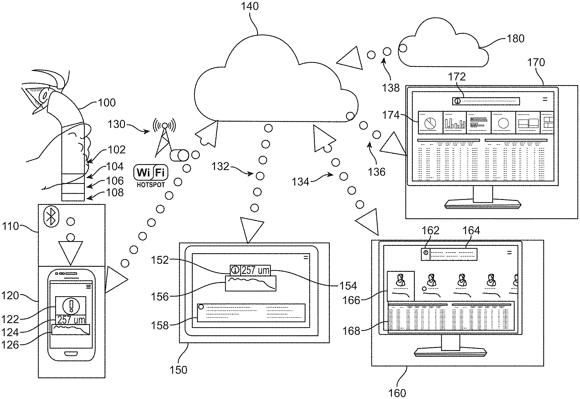
[0079] FIG. 2 shows a schematic of a system allowing a patient to measure RT or RLT at multiple time points and to communicate the results, in accordance with some embodiments. The patient looks into a handheld OCT device 100 to obtain a measurement of the RT or RLT. In some embodiments, the handheld OCT device comprises optics 102, electronics 104 to control and communicate with the optics, a battery 106, and a transmitter 108. In some instances, the transmitter is a wired transmitter. In some cases, the transmitter is a wireless transmitter. In some cases, the handheld OCT device communicates the results via a wireless communication channel 110 to a mobile patient device 120 on the patient's smartphone or other portable electronic device. In some cases, the wireless communication is via Bluetooth communication. In some embodiments, the wireless communication is via Wi-Fi communication. In other embodiments, the wireless communication is via any other wireless communication known to one having skill in the art.
[0080] In some cases, the results are fully processed measurements of the RT. In some cases, all processing of the OCT data is performed on the handheld OCT device. For instance, in some embodiments, the handheld OCT device includes hardware or software elements that allow the OCT optical waveforms to be converted into electronic representations. In some cases, the handheld OCT device further includes hardware or software elements that allow processing of the electronic representations to extract, for instance, a measurement of the RT.
[0081] In some cases, the results are electronic representations of the raw optical waveforms obtained from the OCT measurement. For instance, in some embodiments, the handheld OCT device includes hardware or software elements that allow the OCT optical waveforms to be converted into electronic representations. In some cases, these electronic representations are then passed to the mobile patient device for further processing to extract, for instance, a measurement of the RT.
[0082] In some cases, the patient receives results and analysis of the RT or RLT measurement on the patient mobile app. In some embodiments, the results include an alert 122 alerting the patient that the results of the measurement fall outside of a normal or healthy range. In some cases, the results also include a display of the measured value 124. For instance, in some cases a measurement of the RT or RLT produces a result of 257 .mu.m. In some instances, this result falls outside of a normal or healthy range. This causes the system to produce an alert and to display the measured value of 257 .mu.m on the patient mobile app. In some embodiments, the results also include a chart 126 showing a history of the patient's RT or RLT over multiple points in time.
[0083] In some instances, the patient mobile device communicates the results of the measurement via a communication means 130 to a cloud-based or other network-based storage and communications system 140. In some embodiments, the communication means is a wired communication means. In some embodiments, the communication means is a wireless communication means. In some cases, the wireless communication is via Wi-Fi communication. In other cases, the wireless communication is via a cellular network. In still other cases, the wireless communication is via any other wireless communication known to one having skill in the art. In specific embodiments, the wireless communication means is configured to allow transmission to or reception from the cloud-based or other network-based storage and communications system.
[0084] Once stored in the cloud, the results are then transmitted to other devices, in specific embodiments. In some cases, the results are transmitted via a first communication channel 132 to a patient device 150 on the patient's computer, tablet, or other electronic device. In some embodiments, the results are transmitted via a second communication channel 134 to a physician device 160 on the patient's physician's computer, tablet, or other electronic device. In some instances, the results are transmitted via a third communication channel 136 to an analytics device 170 on another user's computer, tablet, or other electronic device. In some embodiments, the results are transmitted via a fourth communication channel 138 to a patient administration system or hospital administration system 180. In some cases, each of the devices has appropriate software instructions to perform the associate function as described herein.
[0085] In specific embodiments, the first communication channel is a wired communication channel or a wireless communication channel. In some cases, the communication is via Ethernet. In other cases, the communication is via a local area network (LAN) or wide area network (WAN). In still other cases, the communication is via Wi-Fi. In yet other cases, the communication is via any other wired or wireless communication known to one having skill in the art. In some embodiments, the first communication channel is configured to allow transmission to or reception from the cloud-based or other network-based storage and communications system. In some cases, the first communication channel is configured to only allow reception from the cloud-based or other network-based storage and communications system.
[0086] In some cases, the second communication channel is a wired communication channel or a wireless communication channel. In some instances, the communication is via Ethernet. In specific embodiments, the communication is via a local area network (LAN) or wide area network (WAN). In other embodiments, the communication is via Wi-Fi. In still other embodiments, the communication is via any other wired or wireless communication known to one having skill in the art. In some cases, the second communication channel is configured to allow transmission to or reception from the cloud-based or other network-based storage and communications system. In some embodiments, the second communication channel is configured to only allow reception from the cloud-based or other network-based storage and communications system.
[0087] In specific cases, the third communication channel is a wired communication channel or a wireless communication channel. In some instances, the communication is via Ethernet. In other instances, the communication is via a local area network (LAN) or wide area network (WAN). In still other instances, the communication is via Wi-Fi. In yet other instances, the communication is via any other wired or wireless communication known to one having skill in the art. In some embodiments, the third communication channel is configured to allow transmission to or reception from the cloud-based or other network-based storage and communications system. In some cases, the third communication channel is configured to only allow reception from the cloud-based or other network-based storage and communications system.
[0088] In some embodiments, the fourth communication channel is a wired communication channel or a wireless communication channel. In some cases, the communication is via Ethernet. In other cases, the communication is via a local area network (LAN) or wide area network (WAN). In still other cases, the communication is via Wi-Fi. In yet other cases, the communication is any other wired or wireless communication known to one having skill in the art. In some instances, the fourth communication channel is configured to allow transmission to or reception from the cloud-based or other network-based storage and communications system. In other cases, the fourth communication channel is configured to only allow reception from the cloud-based or other network-based storage and communications system.
[0089] A determination of the RT or RLT can be performed at many locations. For instance, a determination of the RT or RLT is performed on the handheld OCT device. In some cases, a determination of the RT or RLT is performed at a location near to the handheld OCT device, such as by a smartphone or other portable electronic device. In some embodiments, a determination of the RT or RLT is performed on the cloud-based storage and communications system. In some instances, he handheld OCT device is configured to compress measurement data and transmit the compressed measurement data to the cloud-based storage and communications system.
[0090] In some embodiments, the patient receives results and analysis of the RT or RLT measurement on the patient device 150. In some instances, the results include an alert 152 alerting the patient that the results of the measurement fall outside of a normal or healthy range. In some cases, the results also include a display of the measured value 154. For instance, in some cases, a measurement of the RT or RLT produces a result of 257 .mu.m. This result falls outside of a normal or healthy range. In some cases, this causes the system to produce an alert and to display the measured value of 257 .mu.m on the patient app. In specific cases, the results also include a chart 156 showing a history of the patient's RT or RLT over multiple points in time. In some cases, the patient device also displays instructions 158 for the patient to follow. In some instances, the instructions instruct the patient to visit their physician. In some embodiments, the instructions include the patient's name, date of most recent RT or RLT measurement, and next scheduled visit to their physician. In other cases, the instructions include more information. In still other cases, the instructions include less information.
[0091] In some embodiments, the patient's physician receives the results and analysis of the RT or RLT measurement on the physician device 160. In some instances, the results include an alert 162 alerting the physician that the results of the measurement fall outside of a normal or healthy range. In some cases, the results also include an alert 164 informing the physician that the patient's measurement falls outside of a normal or healthy range. In some embodiments, the alert includes a suggestion that the physician call the patient to schedule an appointment or to provide medical assistance. In some embodiments, the results also include a display 166 showing the most recent measurements and historical measurements for each of the physician's patients. For instance, in some instances, a measurement of the RT or RLT produces a result of 257 .mu.m. This result falls outside of a normal or healthy range. In some cases, this causes the system to produce an alert and to display the measured value of 257 .mu.m on the physician app. In specific cases, the physician device also displays contact and historical information 168 for each of the physician's patients.
[0092] In some embodiments, the other user receives results and analysis of the RT or RLT measurement on the analytics device 170. In some instances, the other user is a researcher investigating the efficacy of a new form of treatment. In other cases, the other user is an auditor monitoring the outcomes of a particular physician or care facility. To protect the patient's privacy, in some cases the analytics device is restricted to receive only a subset of a given patient's information. For instance, the subset is restricted so as not to include any personally identifying information about a given patient. In some cases, the results include an alert 172 alerting that a large number of abnormal or unhealthy measurements have been obtained in a specific period of time. In some cases, the results include one or more graphical representations 174 of the measurements across a population of patients.
[0093] In some cases, the results and analysis on the analytics device comprise disease information such as a physician-confirmed diagnosis. In some cases, the results and analysis comprise anonymized patient data such as age, gender, genetic information, information about the patient's environment, smoking history, other diseases suffered by the patient, etc. In some cases, the results and analysis comprise anonymized treatment plans for the patient, such as a list of prescribed medications, treatment history, etc. In some cases, the results and analysis comprise measurement results, such as the results of an RT or RLT measurement, a visual function test, or the patient's compliance with a course of treatment. In some cases, the results and analysis comprise data from an electronic medical record. In some cases, the results and analysis comprise diagnostic information from visits to a patient's medical provider, such as the results of an OCT scan acquired by the patient's medical provider.
[0094] In some embodiments, the patient's clinical, hospital, or other health provider receives results and analysis of the RT or RLT measurement on the patient administration system or hospital administration system 180. In some cases, this system contains the patient's electronic medical record. In some cases, the results and analysis provide the patient's health provider with data allowing the provider to update the treatment plan for the patient. In some instances, the results and analysis allow the provider to decide to call the patient in for an early office visit. In some instances, the results and analysis allow the provider to decide to postpone an office visit.
[0095] In some embodiments, one or more of the patient device, physician device, and analytics device includes a software app comprising instructions to perform the functions of the patient device, physician device, or analytics device, respectively, as described herein.
[0096] FIG. 3A shows a handheld OCT device utilizing short-range wireless communication, in accordance with some embodiments. In some embodiments, the handheld OCT device 100 comprises optics 102, electronics to control and communicate with the optics 104, a battery 106, and a wireless transmitter 108. In some cases, the wireless transmitter is a Bluetooth transmitter. In some instances, the results from one or more RT or RLT measurements are stored on the handheld OCT device until an authorized user, such as the patient or another person designated by the patient, opens the patient mobile device on a smartphone or other portable electronic device. Once opened, the patient mobile device establishes wireless communication with the handheld OCT device. In some cases, the communication is via a Bluetooth wireless communication channel 110. In some instances, the handheld OCT device communicates the results via the Bluetooth channel to a mobile patient device 120 on the patient's smartphone or other portable electronic device.
[0097] In some instances, the results include an alert 122 alerting the patient that the results of the measurement fall outside of a normal or healthy range. In specific embodiments, the results also include a display of the measured value 124. For instance, a measurement of the RT or RLT produces a result of 257 .mu.m in some cases. This result falls outside of a normal or healthy range. In some cases, this causes the system to produce an alert and to display the measured value of 257 .mu.m on the patient mobile app. In specific embodiments, the results also include a chart 126 showing a history of the patient's RT or RLT over multiple points in time.
[0098] In some cases, the patient mobile device communicates the results of the measurement via a wireless communication means 130 to a cloud-based or other network-based storage and communications system 140. In some instances, the wireless communication is via Wi-Fi communication. In other cases, the Wi-Fi communication is via a secure Wi-Fi channel. In still other cases, the wireless communication is via a cellular network. In specific embodiments, the cellular network is a secure cellular network. In other embodiments, the transmitted information is encrypted. In some cases, the communication channel is configured to allow transmission to or reception from the cloud-based or other network-based storage and communications system. In some cases, data is stored on the smartphone or other portable electronic device until the smartphone or other portable electronic device connects to a Wi-Fi or cellular network.
[0099] In some cases, the patient mobile device has a feature which notifies the patient or another person designated by the patient when too much time has elapsed since the patient mobile device was last opened. For instance, in some cases this notification occurs because the patient has not acquired measurements of the RT or RLT as recently as required by measuring schedule set by their physician or other healthcare provider. In other cases, the notification occurs because the handheld OCT device has been storing the results of too many measurements and needs to transmit the data to the patient's smartphone. In specific embodiments, the patient mobile device communicates with the cloud-based or other network-based storage and communications system to display a complete set of patient data.
[0100] FIG. 3B shows a handheld OCT device capable of communicating directly with a cloud-based storage and communication system without reliance on a user device such as a smartphone, in accordance with some embodiments. In some embodiments, the handheld OCT device 100 comprises optics 102, electronics to control and communicate with the optics 104, a battery 106, and a wireless transmitter 108. In some cases, the wireless transmitter is a GSM transmitter. In some instances, the results from one or more RT or RLT measurements are stored on the handheld OCT device. In some cases, the GSM transmitter establishes wireless communication with a cloud-based or other network-based storage and communications system 140 via a wireless communication channel 114. In specific cases, the wireless communication is via a GSM wireless communication channel. In other embodiments, the system utilizes third generation (3G) or fourth generation (4G) mobile communications standards. In such cases, the wireless communication is via a 3G or 4G communication channel.
[0101] In specific embodiments, the patient mobile device 120 receives the results of the measurement via a wireless communication means 130 from the cloud-based or other network-based storage and communications system 140. In some cases, the wireless communication is via Wi-Fi communication. In some cases, the Wi-Fi communication is via a secure Wi-Fi channel. In other cases, the wireless communication is via a cellular network. In some cases, the cellular network is a secure cellular network. In specific instances, the transmitted information is encrypted. In some embodiments, the communication channel is configured to allow transmission to or reception from the cloud-based or other network-based storage and communications system.
[0102] Once obtained from the cloud-based or other network-based storage and communications system, the results of the RT or RLT measurement are viewed in the patient mobile app, in some instances. In some cases, the results include an alert 122 alerting the patient that the results of the measurement fall outside of a normal or healthy range. In some instances, the results also include a display of the measured value 124. For instance, in some cases a measurement of the RT or RLT produces a result of 257 .mu.m. This result falls outside of a normal or healthy range. In specific embodiments, this causes the system to produce an alert and to display the measured value of 257 .mu.m on the patient mobile app. In some embodiments, the results also include a chart 126 showing a history of the patient's RT or RLT over multiple points in time.
[0103] In some cases, the patient mobile device has a feature which notifies the patient or another person designated by the patient when too much time has elapsed since the patient mobile device was last opened. For instance, in some cases this notification occurs because the patient has not acquired measurements of the RT or RLT as recently as required by measuring schedule set by their physician or other healthcare provider. In other cases, the notification occurs because the handheld OCT device has been storing the results of too many measurements and needs to transmit the data to the patient's smartphone. In specific embodiments, the patient mobile device communicates with the cloud-based or other network-based storage and communications system to display a complete set of patient data.
[0104] In some cases, the handheld OCT device comprises both a short-range transmitter and a GSM, 3G, or 4G transmitter. In some instances, the short-range transmitter is a Bluetooth transmitter. In some cases, the handheld OCT device communicates directly with the patient mobile device on a smartphone or other portable electronic device through the Bluetooth wireless communication channel. In some embodiments, the handheld OCT also communicates with the cloud-based or other network-based storage and communications system through the GSM, 3G, or 4G wireless communication channel. In specific cases, the cloud-based system then communicates with the patient mobile device through a Wi-Fi, cellular, or other wireless communication channel. Alternatively, the Bluetooth transmitter is built into a docking station. In some instances, this allows for the use of older devices for patients who lack a smartphone. In some cases, the docking station also includes a means for charging the battery of the handheld OCT device.
[0105] In some cases, the handheld OCT device of FIGS. 3A and 3B is configured to be held in close proximity to the eye. For instance, in specific embodiments, the device is configured to be held in front of the eye with the detector at a distance of no more than 200 mm from the eye. In other embodiments, the devices are configured to be held in front of the eye with the detector at a distance of no more than 150 mm, no more than 100 mm, or no more than 50 mm from the eye. In specific instances, the handheld OCT devices further comprise housing to support the light source, optical elements, detector, and circuitry. In some cases, the housing is configured to be held in a hand of a user. In some cases, the user holds the devices in front of the eye to direct the light beam into the eye. In some instances, the devices include a sensor to measure which eye is being measured. For instance, in specific embodiments, the devices include an accelerometer or gyroscope to determine which eye is measured in response to an orientation of the housing. The devices optionally include an occlusion structure coupled to the housing and the sensor that determines which eye is measured. The occlusion structure occludes one eye while the other eye is measured. In some cases, the devices include a viewing target to align the light beams with a portion of the retina. For instance, in specific embodiments, the devices include a viewing target to align the light beams with a fovea of the eye. In some cases, the viewing target is a light beam. In some cases, the viewing target is a light emitting diode. In other cases, the viewing target is a vertical cavity surface emitting laser (VCSEL). In still further cases, the viewing target is any viewing target known to one having skill in the art.
[0106] The optical components described herein are capable of being miniaturized so as to provide the handheld OCT device with a reduced physical size and mass, as described herein, as will be appreciated by one of ordinary skill in the art.
[0107] In many embodiments, the handheld OCT devices of FIGS. 3A and 3B are small enough and light enough to be easily manipulated with one hand by a user. For instance, in many embodiments, the device has a mass within a range from about 100 grams to about 500 grams. In many embodiments, the device has a mass within a range from about 200 grams to about 400 grams. In many embodiments, the device has a mass within a range from about 250 grams to about 350 grams. In specific embodiments, the device has a maximum distance across within a range from about 80 mm to about 160 mm. In specific embodiments, the device has a maximum distance across within a range from about 100 mm to about 140 mm. In specific embodiments, the device has a width within a range from about 110 mm to about 130 mm. In some embodiments, the maximum distance across comprises a length. In some embodiments, the device has a width less than its length. In specific embodiments, the device has a width within a range from about 40 mm to about 80 mm. In specific embodiments, the device has a width within a range from about 50 mm to about 70 mm. In specific embodiments, the device has a width within a range from about 55 mm to about 65 mm.
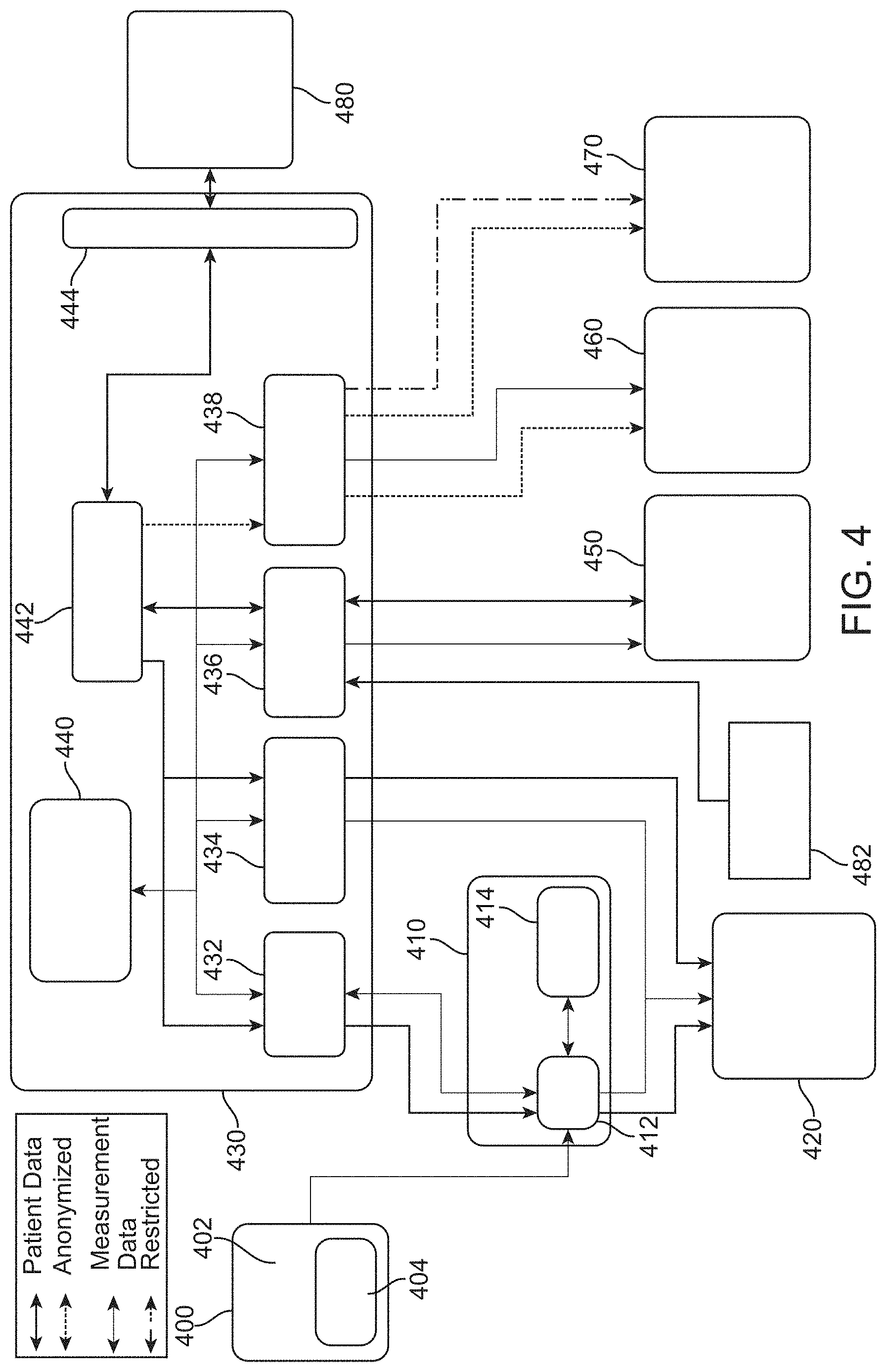
[0108] FIG. 4 shows a diagram of the flow of information in the handheld OCT system, in accordance with some embodiments. In some cases, the handheld OCT device 400 further comprises a subsystem 402 for measuring RT or RLT and a device storage system 404. In some embodiments, the device storage system comprises any form of volatile or non-volatile memory, including but not limited to Flash memory or random access memory (RAM). In some instances, the subsystem for measuring RT or RLT is communicatively coupled to the device storage system. In some cases, the handheld OCT device transmits measurement data to a smartphone or any other computing device 410. For example, in some cases the smartphone or another handheld device further comprises a smartphone storage system 414 and run a smartphone app 412.
[0109] In some cases, the computing device sends patient data and measurement data to a patient device 420. In some embodiments, the smartphone device is communicatively coupled to a cloud-based or other network-based storage and communications system 430. In some instances, the cloud-based or other network-based storage system further comprises any of a mobile application programming interface (API) 432, a patient device 434, a physician device 436, an analytics device 438, a measurement and treatment storage system 440, a patient data storage system 442, and an API 444 interfacing with a patient administration system or a hospital administration system.
[0110] In some cases, the mobile API is communicatively couple to the smartphone app. In some embodiments, the mobile API is configured to send and receive measurement information (e.g. measurements of the RT) to and from the smartphone app. In some instances, the mobile API is configured to send patient data (e.g. identifying information or demographic information) to the smartphone device but not to receive this information from the smartphone app. In some cases, this configuration is designed to reduce the likelihood of compromising patient data. In some embodiments, the mobile API is configured to send measurement data and patient data to the patient device and to receive measurement data and patient data from the patient app. In some instances, the patient device is further configured to send measurement data and patient data to the patient and to receive measurement data and patient data from the patient.
[0111] In some cases, the mobile API is configured to send measurement data and patient data to the physician device and to receive measurement data and patient data from the physician app. In other cases, the mobile API is configured to send measurement data to the physician device and to receive measurement data and from the physician device but require patient data to first pass through a patient data storage system. In such a case, the patient data storage system is configured to send patient data to the physician device and receive patient data from the physician app. In some embodiments, the patient data storage system is configured to send patient data to the API interfacing with a patient administration system or a hospital administration system and to receive patient data from the API interfacing with a patient administration system or a hospital administration system. In some instances, the API interfacing with a patient administration system or a hospital administration system is configured to send patient data to a patient administration system or hospital administration system 480 and to receive patient data from the patient administration system or hospital administration system. In some cases, the physician device is further configured to send measurement data and patient data to a physician 450 and to receive measurement data and patient data from the physician.
[0112] In some cases, the mobile API is configured to send measurement data to the analytics apps and to receive measurement data from the analytics app. In some embodiments, the analytics device is configured to send measurement data to the manufacturer or developer of the handheld OCT system 460. In some instances, the analytics device is configured to send anonymized patient data to the manufacturer or developer of the handheld OCT system. In some cases, the analytics device is configured to send a subset of the measurement data to other parties 470. In some embodiments, the analytics device is configured to send anonymized patient data to other parties 470.
[0113] In some embodiments, the cloud-based or other network-based storage and communications system further comprise a measurement and treatment storage system. In some instances, the measurement and treatment storage system is configured to send measurement data to any of the mobile API, the patient app, the physician app, and the analytics app. In some cases, the measurement and treatment storage system is configured to receive measurement data from any of the mobile API, the patient app, the physician app, and the analytics app.
[0114] In addition to the patient administration system or hospital information system, in some cases the cloud-based or other network-based storage and communications system is communicatively coupled to a local patient administration system 482. In some embodiments, the local patient administration system is configured to send patient data to the physician app.
[0115] The handheld OCT device may utilize any method for optical coherence tomography. In some cases, the handheld OCT device utilizes time domain OCT. In some embodiments, the handheld OCT device utilizes frequency domain OCT. In some instances, the handheld OCT device utilizes spatially encoded frequency domain OCT. In some cases, the handheld OCT device utilizes time encoded frequency domain OCT, also known as swept source OCT (SS-OCT).
[0116] FIG. 5 shows a schematic for the optics of a swept source optical coherence tomography (SS-OCT) device, in accordance with some embodiments. In some cases, the optics 102 comprises a light source 500, a beamsplitter 510, front-end optics 520, a reference mirror 530, and a processing unit 540. In some embodiments, the processing unit further comprises a photodetector 542 and a signal processing module 544. Light from the light source impinges upon the beamsplitter. A portion of the light is directed along a reference arm to a reference mirror and a portion of the light is directed to the front-end optics and then to the sample 550. In some instances, the sample comprises an eye. In some cases, the sample comprises a retina. In some embodiments, the retina comprises a number of layers of tissue. In some instances, the layers of tissue comprise a layer of light-sensitive rod and cone cells 552, the retinal pigment epithelium (RPE) 554, and the choroid 556. In other instances, the layers of tissue comprise other layers of the retina, such as the nerve fiber layer, the ganglion cell layer, the inner plexiform layer, the inner nuclear layer, the outer plexiform layer, the outer nuclear layer, the inner limiting membrane, the external limiting membrane, and/or Bruch's membrane. Light is reflected back to the device at each boundary of each of the layers. Light reflected from each boundary interferes with light reflected from the reference mirror and with light reflected from any other boundary. The interference signal is detected at the photodetector. In some instances, light is reflected from the posterior surface of the layer of rod and cone cells, the anterior surface of the layer of rod and cone cells, the posterior surface of the inner limiting membrane, the anterior surface of the inner limiting membrane, the posterior surface of the choroid, and/or the anterior surface of the choroid. Light may be reflected from any surface of any other layer, such as the nerve fiber layer, the ganglion cell layer, the inner plexiform layer, the inner nuclear layer, the outer plexiform layer, the outer nuclear layer, the external limiting membrane, and/or the retinal pigment epithelium. In some cases, a RLT corresponds to a thickness of any of these retinal layers, or a thickness between any two such layers.
[0117] This process is repeated over the range of wavelengths emitted by the light source. The amplitude of the interference signal varies with wavelength and attains a maximum value when the light reflected from a boundary and the light reflected from the reference mirror are in phase or when the light reflected from a boundary is in phase with light reflected from another boundary. This condition is attained at one or more particular wavelengths of light for each boundary and is characterized by one or more maxima in the interference signal. At other wavelengths, the interference signal displays partial constructive interference or destructive interference. The interference signals at all wavelengths are compiled to form an interferogram 560. The interferogram is subjected to a signal analysis procedure. In some cases, the interferogram is subjected to a frequency analysis procedure, such as a fast Fourier transform (FFT), to form a spectrum 570. The spectrum comprises peaks corresponding to the interference signals associated with the thickness of various retinal layers. In some embodiments, the SS-OCT utilizes a light source with a relatively long coherence length (typically greater than a few millimeters). In some instances, the amplitude of the interference signal decreases as the distance between two retinal layers increases. In some cases, the position of a peak is indicative of the thickness of each layer of the tissue.
[0118] In some cases, the light source comprises a laser source. In some embodiments, the laser source produces laser light having a wavelength that may be tuned. In some instances, the laser source is scanned over a range of wavelengths in order to obtain an OCT signal. In some cases, the laser source is capable of being scanned rapidly to allow rapid attainment of the OCT signal. In some cases, the laser source comprises a vertical cavity surface emitting laser (VCSEL) laser. In some embodiments, the VCSEL is tuned by varying the electrical current provided to the VCSEL. In some instances, the VCSEL is scanned continuously across a range of wavelengths by continuously varying the electrical current. In some cases, the VCSEL is periodically scanned across a range of wavelengths by periodically varying the electrical current. In some embodiments, the VCSEL is provided with a sinusoidally varying electrical current to produce a sinusoidally varying wavelength.
[0119] In some embodiments, the VCSEL is a commercially available VCSEL. In some instances, the VCSEL is a VCSEL modified from a commercially available VCSEL based on the teachings described herein. In some cases, the VCSEL is a VCSEL obtained from manufacturers such as Phillips Photonics, Frankfurt Laser Company, Hamamatsu Corporation, New Focus, Power Technology, Avago Technologies, Masimo Semiconductor, Finisar, Oclaro, or any other manufacturer known to one having skill in the art.
[0120] In some instances, the VCSEL has a maximum recommended current for continuous use or for pulsed use. In some cases, the maximum continuous current rating limits the range of wavelengths over which the VCSEL may be swept. For instance, the VCSEL may be limited to a continuous operating current no more than 1 mA, 2 mA, 3 mA, 4 mA, 5 mA, 6 mA, 7 mA, 8 mA, 9 mA, or 10 mA. In some embodiments, the wavelength emitted by the VCSEL varies linearly with the operating current with a proportionality constant of 0.3 nm/mA. In some cases, this limits the range of wavelengths over which the VCSEL may be swept to 0.3 nm, 0.6 nm, 0.9 nm, 1.2 nm, 1.5 nm, 1.8 nm, 2.1 nm, 2.4 nm, 2.7 nm, or 3.0 nm. In some embodiments, this limits the attainable axial resolution of the VCSEL-based SS-OCT device. Assuming a Gaussian spectrum from the light source, the attainable axial resolution is determined according to:
.delta. z = 2 ln 2 .lamda. 0 2 .pi. .DELTA. .lamda. ( 1 ) ##EQU00001##
Here, .delta.z is the attainable axial resolution, .lamda..sub.0 is the central emission wavelength of the VCSEL, and .DELTA..lamda. is the range of wavelengths over which the VCSEL operates.
[0121] Thus, in some cases, the limited operating range of the VCSEL limits the attainable axial resolution. In some embodiments, for a VCSEL with a central operating wavelength of 850 nm, the attainable axial resolution is no better than 1062 .mu.m, 531 .mu.m, 354 .mu.m, 266 .mu.m, 213 .mu.m, 177 .mu.m, 152 .mu.m, 133 .mu.m, 118 .mu.m, or 106 .mu.m for operating ranges of 0.3 nm, 0.6 nm, 0.9 nm, 1.2 nm, 1.5 nm, 1.8 nm, 2.1 nm, 2.4 nm, 2.7 nm, and 3.0 nm, respectively. In some instances, the VCSEL emits no more than 0.01 mW, 0.025 mW, 0.05 mW, 0.1 mW, 0.25 mW, 0.5 mW 1 mW, 2.5 mW, 5 mW, 10 mW, 25 mW, 50 mW, 100 mW, 250 mW, 500 mW, 1 W, 2.5 W, 5 W, 10 W, 25 W, 50 W, or 100 W of optical power.
[0122] Table 1 shows axial resolution for the corresponding wavelength range of the swept source for a central operating wavelength of 850 nm.
TABLE-US-00001 Wavelength Range (nm) Axial Resolution (.mu.m) 0.3 1062.7 0.6 531.4 0.9 354.2 1.2 265.7 1.5 212.5 1.8 177.1 2.1 151.8 2.4 132.8 2.7 118.1 3.0 106.3 4.0 79.7 5.0 63.8 6.0 53.1 7.0 45.5 8.0 39.9 9.0 35.4 10.0 31.9
[0123] Although Table 1 makes reference to a central wavelength of 850 nm, a person of ordinary skill in the art can construct a compact OCT system operating at a different central wavelength with similar sweep ranges and similar resolutions in accordance with the disclosure provided herein. Also, a person of ordinary skill in the art can readily correct the above values in accordance with the index of refraction of the retina, which is generally between about 1.3 and 1.4.
[0124] In some cases, additional VSCELs are used to extend the swept wavelength range as described herein.
[0125] In some cases, the limited operating range of the VCSEL also limits the ability to extract information from the OCT signal due to a limited phase shift imparted by a limited optical path difference (OPD). The phase shift between light reflected from a first interface and light reflected from a second interface is given by:
.DELTA. .PHI. = 4 .pi. .lamda. 0 2 n .DELTA. z .DELTA. .lamda. ( 2 ) ##EQU00002##
Here, .DELTA..PHI. is the phase shift, .lamda..sub.0 is the central emission wavelength of the VCSEL, n is the index of refraction of the medium between the first and second reflecting interfaces, .DELTA.z is the distance between the first and second reflecting interfaces, n.DELTA.z is the OPD, and .DELTA..lamda. is the range of wavelengths over which the VCSEL operates.
[0126] In some cases, it is useful to extract frequency information from the interference signal arising from the interaction of light reflected from the first interface and light reflected from the second interface. In order to extract this information, it may be helpful to attain two signal periods of the interferogram. This corresponds to a phase shift of 4.pi.. Thus, a VCSEL should operate over a minimum range of wavelengths .DELTA..lamda..sub.min given by:
.DELTA. .lamda. min = .lamda. 0 2 n .DELTA. z ( 3 ) ##EQU00003##
[0127] Thus, in some cases, the limited operating range of the VCSEL limits the ability to attain sufficient phase shifts to extract frequency information from an interference signal in some cases, for example. In some embodiments, for a VCSEL with a central operating wavelength of 850 nm, forming interference patterns between reflecting interfaces separated by 150 .mu.m in a medium with an index of refraction of 1.3, similar to a retina, a minimum range of wavelengths is 3.7 nm. In some instances, this range of wavelengths is greater than the range of wavelengths that is typically emitted by a VCSEL operated within its maximum recommended current for continuous use. Thus, in some cases, it is be helpful to extend the range of wavelengths emitted by the VCSEL in order to produce a sufficient phase shift.
[0128] The light source need not be a VCSEL. In some cases, the light source is doped fiber amplifier utilizing amplified spontaneous emission (ASE). In some cases, the light source is a superluminescent diode (SLD). Additionally, in some embodiments, the light source comprises multiple light sources.
[0129] In some cases, the front-end optics comprise optical elements such as lenses. In some embodiments, the front-end optics comprise any reflective, refractive, or diffractive elements. In some instances, the front-end optics comprise more than one reflective, refractive, or diffractive elements. In some cases, the front-end optics comprise electro-optic, magneto-optic, acousto-optic, or mechano-optic devices. In some embodiments, the front-end optics comprise any optical elements known to one having skill in the art.
[0130] In some embodiments, the front end optics comprise a scanning optical element to allow the light source to be moved to different locations on the retina. In some instances, this allows multiple measurements to be conducted to determine a RT or RLT at different locations on the retina. In some cases, determining a RT or RLT at different locations on the retina further allows the location of the fovea to be ascertained. In some embodiments, the scanning optical element is selected from the group consisting of a mirror, a plurality of mirrors, a gimbal, a lens, a galvanometer, an acousto-optic modulator, an electro-optic modulator, a translating optical element, an optical element translating transverse to the light beam, a deformable mirror and an xy translation stage. In some instances, the scanning optical element comprises any scanning optical element as is known to one having skill in the art.
[0131] In some instances, the device further comprises a scanning optical element as described herein.
[0132] FIG. 6A shows a schematic for the optics of a swept source optical coherence tomography (SS-OCT) device lacking a reference mirror, in accordance with some embodiments. In some cases, the optics 102 comprise a VCSEL or other light source 600, a beamsplitter 610, front-end optics 620, and a processing unit 640. In some embodiments, the processing unit further comprises a photodetector 642 and a signal processing module 644. Light from the broadband source impinges upon the beamsplitter. Light is directed to the front-end optics and then to the sample 650. Light is reflected back to the device at each boundary of each layer. Light reflected from a boundary of one layer interferes with light reflected from a boundary of another layer. The interference signal is detected at the photodetector.
[0133] This process is repeated over the range of wavelengths emitted by the light source. The amplitude of the interference signal varies with wavelength and attains a maximum value when the light reflected from a boundary is in phase with light reflected from another boundary. This condition is attained at one or more particular wavelengths of light for each boundary and is characterized by one or more maxima in the interference signal. At other wavelengths, the interference signal displays partial constructive interference or destructive interference. The interference signals at all wavelengths are compiled to form an interferogram. The interferogram is subjected to a signal analysis procedure. In some cases, the interferogram is subjected to a frequency analysis procedure, such as a fast Fourier transform (FFT), to form a spectrum. The spectrum comprises peaks corresponding to the wavelengths associated with an interference maximum for each boundary. In some embodiments, the SS-OCT utilizes a light source with a relatively long coherence length (typically greater than a few millimeters). In some instances, the amplitude of the interference signal decreases as the distance between two retinal layers increases. In some cases, the position of a peak is indicative of the thickness of each layer of the tissue.
[0134] In some cases, the light source comprises a laser source. In some embodiments, the laser source produces laser light having a wavelength that may be tuned. In some instances, the laser source is scanned over a range of wavelengths in order to obtain an OCT signal. In some cases, the laser source is capable of being scanned rapidly to allow rapid attainment of the OCT signal. In some embodiments, the laser source comprises a vertical cavity surface emitting laser (VCSEL) laser. In some instances, the VCSEL is tuned by varying the electrical current provided to the VCSEL. In some cases, the VCSEL is scanned continuously across a range of wavelengths by continuously varying the electrical current. In some embodiments, the VCSEL is periodically scanned across a range of wavelengths by periodically varying the electrical current. For instance, the VCSEL may be provided with a sinusoidally varying electrical current to produce a sinusoidally varying wavelength.
[0135] In some embodiments, the front-end optics comprise optical elements such as lenses. In some instances, the front-end optics comprise any reflective, refractive, or diffractive elements. In some cases, the front-end optics comprise more than one reflective, refractive, or diffractive elements. In some embodiments, the front-end optics comprise electro-optic, magneto-optic, acousto-optic, or mechano-optic devices. The front-end optics may comprise any optical elements known to one having skill in the art.
[0136] FIG. 6B shows the wavelength range over which the VCSEL operates in the swept source optical coherence tomography (SS-OCT) device lacking a reference mirror, in accordance with some embodiments. In some cases, the VCSEL has a maximum recommended current for continuous use. In some embodiments, the maximum continuous current rating limits the range of wavelengths over which the VCSEL may be swept. In some instances, the VCSEL is limited to a continuous operating current no more than 1 mA, 2 mA, 3 mA, 4 mA, 5 mA, 6 mA, 7 mA, 8 mA, 9 mA, or 10 mA. In some cases, the wavelength emitted by the VCSEL varies linearly with the operating current with a proportionality constant of 0.3 nm/mA. In some embodiments, this limits the range of wavelengths over which the VCSEL may be swept to 0.3 nm, 0.6 nm, 0.9 nm, 1.2 nm, 1.5 nm, 1.8 nm, 2.1 nm, 2.4 nm, 2.7 nm, or 3.0 nm. In some instances, this limits the attainable axial resolution of the VCSEL-based SS-OCT device.
[0137] Thus, in some cases, the limited operating range of the VCSEL limits the attainable axial resolution. For instance, for a VCSEL with a central operating wavelength of 850 nm, the attainable axial resolution is no better than 1062 .mu.m, 531 .mu.m, 354 .mu.m, 266 .mu.m, 213 .mu.m, 177 .mu.m, 152 .mu.m, 133 .mu.m, 118 .mu.m, or 106 .mu.m for operating ranges of 0.3 nm, 0.6 nm, 0.9 nm, 1.2 nm, 1.5 nm, 1.8 nm, 2.1 nm, 2.4 nm, 2.7 nm, and 3.0 nm, respectively. In some embodiments, the VCSEL emits no more than 0.01 mW, 0.025 mW, 0.05 mW, 0.1 mW, 0.25 mW, 0.5 mW 1 mW, 2.5 mW, 5 mW, 10 mW, 25 mW, 50 mW, 100 mW, 250 mW, 500 mW, 1 W, 2.5 W, 5 W, 10 W, 25 W, 50 W, or 100 W of optical power.
[0138] The light source need not be a VCSEL. In some cases, the light source is a doped fiber amplifier utilizing amplified spontaneous emission (ASE). In some cases, the light source is a superluminescent diode (SLD). Additionally, in some embodiments, the light source comprises multiple light sources.
[0139] Regardless of whether the SS-OCT device utilizes a reference mirror or not, the limited frequency range of the VCSEL causes the SS-OCT device to have an attainable axial resolution value less than about 100 .mu.m.
[0140] FIG. 7A shows a schematic for the optics of a swept source optical coherence tomography (SS-OCT) device utilizing a reference mirror, in accordance with some embodiments. In some cases, the optics 102 comprise a VCSEL or other light source 700, a beamsplitter 710, front-end optics 720, a reference mirror 730, and a processing unit 740. In some embodiments, the processing unit further comprises a photodetector 742 and a signal processing module 744. Light from the light source impinges upon the beamsplitter. A portion of the light is directed along a reference arm to a reference mirror and a portion of the light is directed to the front-end optics and then to the sample 750. Light is reflected back to the device at each boundary of each layer. Light reflected from each boundary interferes with light reflected from the reference mirror and with light reflected from any other boundary. The interference signal is detected at the photodetector.
[0141] This process is repeated over the range of wavelengths emitted by the light source. The amplitude of the interference signal varies with wavelength and attains a maximum value when the light reflected from a boundary and the light reflected from the reference mirror are in phase or when the light reflected from a boundary is in phase with light reflected from another boundary. This condition is attained at one or more particular wavelengths of light for each boundary and is characterized by one or more maxima in the interference signal. At other wavelengths, the interference signal displays partial constructive interference or destructive interference. The interference signals at all wavelengths are compiled to form an interferogram. The interferogram is subjected to a signal analysis procedure. In some cases, the interferogram is subjected to a frequency analysis procedure, such as a fast Fourier transform (FFT), to form a spectrum. The spectrum comprises peaks corresponding to the wavelengths associated with an interference maximum for each boundary. In some cases, the SS-OCT utilizes a light source with a relatively long coherence length (typically greater than a few millimeters). In some embodiments, the amplitude of the interference signal decreases as the distance between two retinal layers increases. In some instances, the position of a peak is indicative of the thickness of each layer of the tissue. The reference mirror allows longer optical path lengths for the light traveling to the sample. In some cases, this has the effect of shifting the frequency at which the maximum interference signal is attained to a higher frequency. In some embodiments, this shift to higher frequency allows for detection of the OCT signal in a manner that is more robust to noise.
[0142] In some cases, the light source comprises a laser source. In some embodiments, the laser source produces laser light having a wavelength that may be tuned. In some instances, the laser source is scanned over a range of wavelengths in order to obtain an OCT signal. In some cases, the laser source is capable of being scanned rapidly to allow rapid attainment of the OCT signal. In some embodiments, the laser source comprises a vertical cavity surface emitting laser (VCSEL) laser. In some instances, the VCSEL is tuned by varying the electrical current provided to the VCSEL. In some cases, the VCSEL is scanned continuously across a range of wavelengths by continuously varying the electrical current. In some embodiments, the VCSEL is periodically scanned across a range of wavelengths by periodically varying the electrical current. For instance, the VCSEL may be provided with a sinusoidally varying electrical current to produce a sinusoidally varying wavelength.
[0143] In some embodiments, the front-end optics comprise optical elements such as lenses. In some instances, the front-end optics comprise any reflective, refractive, or diffractive elements. In some cases, the front-end optics comprise more than one reflective, refractive, or diffractive elements. In some embodiments, the front-end optics comprise electro-optic, magneto-optic, acousto-optic, or mechano-optic devices. The front-end optics may comprise any optical elements known to one having skill in the art.
[0144] In some cases, the front end optics comprise a scanning optical element as described herein.
[0145] FIG. 7B shows the wavelength range over which the VCSEL operates in the swept source optical coherence tomography (SS-OCT) device lacking a reference mirror, in accordance with some embodiments. The light source emits light with a central wavelength .lamda.. The central wavelength is varied over a range of wavelengths .DELTA..lamda..
[0146] FIG. 7C shows how a reference mirror may shift the OCT peaks to a higher optical frequency compared to the frequency of the OCT peak in the absence of the reference mirror. In the absence of the reference mirror, the OCT peak of a given sample is obtained at a relatively low frequency, indicated by t(encoded). This frequency correspond to the optical path difference in the sample. The present of the reference mirror has the effect that each boundary of a sample interferes with the reference mirror. For a sample with two boundaries, this effect gives rise to two relatively high frequency components in the OCT signal, denoted as d(encoded) and d+t(encoded) in FIG. 7C. The difference between these two frequencies corresponds to the distance between the boundaries of the sample. For a retina or retinal layer, the different thus corresponds to a RT or RLT, respectively.
[0147] In some cases, the VCSEL has a maximum recommended current for continuous use. In some embodiments, the maximum continuous current rating limits the range of wavelengths over which the VCSEL may be swept. In some instances, the VCSEL is limited to a continuous operating current no more than 1 mA, 2 mA, 3 mA, 4 mA, 5 mA, 6 mA, 7 mA, 8 mA, 9 mA, or 10 mA. In some cases, the wavelength emitted by the VCSEL varies linearly with the operating current with a proportionality constant of 0.3 nm/mA. In some embodiments, this current limit limits the range of wavelengths over which the VCSEL may be swept. In some instances, the VCSEL is swept over a range defined by any two of the following numbers: 0.3 nm, 0.6 nm, 0.9 nm, 1.2 nm, 1.5 nm, 1.8 nm, 2.1 nm, 2.4 nm, 2.7 nm, or 3.0 nm. In some cases, this sweeping range limit limits the attainable axial resolution of the VCSEL-based SS-OCT device. In some embodiments, the sweep range is increased by driving the current beyond the maximum current rating, as described herein.
[0148] Thus, in some cases, the limited operating range of the VCSEL limits the attainable axial resolution. In some embodiments, for a VCSEL with a central operating wavelength of 850 nm, the attainable axial resolution is no better than 1062 .mu.m, 531 .mu.m, 354 .mu.m, 266 .mu.m, 213 .mu.m, 177 .mu.m, 152 .mu.m, 133 .mu.m, 118 .mu.m, or 106 .mu.m for operating ranges of 0.3 nm, 0.6 nm, 0.9 nm, 1.2 nm, 1.5 nm, 1.8 nm, 2.1 nm, 2.4 nm, 2.7 nm, and 3.0 nm, respectively. In some instances, the VCSEL emits no more than 0.01 mW, 0.025 mW, 0.05 mW, 0.1 mW, 0.25 mW, 0.5 mW 1 mW, 2.5 mW, 5 mW, 10 mW, 25 mW, 50 mW, 100 mW, 250 mW, 500 mW, 1 W, 2.5 W, 5 W, 10 W, 25 W, 50 W, or 100 W of optical power.
[0149] The light source need not be a VCSEL. In some cases, the light source is a doped fiber amplifier utilizing amplified spontaneous emission (ASE). In some cases, the light source is a superluminescent diode (SLD). Additionally, in some embodiments, the light source comprises multiple light sources.
[0150] In some cases, the limited attainable axial resolution is improved by utilizing two or more VCSELs or other light sources in the SS-OCT system. In some embodiments, each of the two or more VCSELs or other light sources has an emission spectrum which is distinct from the emission spectra of each of the other VCSELs or other light sources. In some cases, the emission spectra of the two or more VCSELs partially overlap. In some cases, the emission spectra of the two or more VCSELs do not overlap. In this manner, in some embodiments, the two or more VCSELs or other light sources combine to produce a wider range of emission wavelengths for the SS-OCT measurement. In some instances, this enhances the attainable axial resolution of the SS-OCT measurement.
[0151] FIG. 8A shows the optics of a swept source optical coherence tomography (SS-OCT) device utilizing two VCSELs and lacking a reference mirror at a first particular point in time, in accordance with some embodiments. In some cases, the optics 102 comprise a first VCSEL or other light source 800, a second VCSEL or other light source 805, a first beamsplitter 810, a second beamsplitter 815, front-end optics 820 as described herein, and a processing unit 840. In some embodiments, the processing unit further comprises a photodetector 842 and a signal processing module 844. Light from the first source impinges upon the beamsplitter. The light is then directed to the front-end optics and then to the sample 850. In some instances, at a first particular point in time, the first VCSEL or other light source is on (sending laser light to the sample) while the second VCSEL or other light source is off (not sending laser light to the sample). Light is reflected back to the device at each boundary of each layer. Light reflected from a boundary of a first layer interferes with light reflected from a back boundary of a second layer. The interference signal is detected at the photodetector.
[0152] FIG. 8B shows a schematic for a swept source optical coherence tomography (SS-OCT) device utilizing two VCSELs and lacking a reference mirror at second particular point in time, in accordance with some embodiments. In some instances, at a second particular point in time, the first VCSEL or other light source is off (not sending laser light to the sample) while the second VCSEL or other light source is on (sending laser light to the sample). Light is reflected back to the device at each boundary of each layer. Light reflected from a boundary of a first layer interferes with light reflected from a boundary of a second layer. The interference signal is detected at the photodetector.
[0153] This process is repeated over the entire range of wavelengths emitted by the first and second light sources. The amplitude of the interference signal varies with wavelength and attains a maximum value when the light reflected from a boundary and the light reflected from the reference mirror are in phase or when the light reflected from a boundary is in phase with light reflected from another boundary. This condition is attained at one or more particular wavelengths of light for each boundary and is characterized by one or more maxima in the interference signal. At other wavelengths, the interference signal displays partial constructive interference or destructive interference. The interference signals at all wavelengths are compiled to form an interferogram. The interferogram is subjected to a signal analysis procedure. In some cases, the interferogram is subjected to a frequency analysis procedure, such as a fast Fourier transform (FFT), to form a spectrum. The spectrum comprises peaks corresponding to the wavelengths associated with an interference maximum for each boundary. In some cases, the SS-OCT utilizes light sources with a short coherence length (typically less than a few millimeters). In such a case, the amplitude of the interference signal decreases rapidly as the wavelength is moved away from the wavelength associated with the interference maximum. In some embodiments, this yields narrow peaks in the frequency spectrum. In some instances, the distances between peaks are indicative of the thickness of each layer of the tissue.
[0154] In some cases, the light sources comprise laser sources. In some embodiments, the laser sources produce laser light having a wavelength that may be tuned. In some instances, the laser sources are scanned over a range of wavelengths in order to obtain an OCT signal. In some cases, the laser sources are capable of being scanned rapidly to allow rapid attainment of the OCT signal. In some embodiments, the laser sources comprise vertical cavity surface emitting laser (VCSEL) lasers. In some instances, the VCSELs are tuned by varying the electrical current provided to the VCSELs. In some cases, the VCSELs are scanned continuously across a range of wavelengths by continuously varying the electrical current. In some embodiments, the VCSELs are periodically scanned across a range of wavelengths by periodically varying the electrical current. For instance, the VCSELs may be provided with a sinusoidally varying electrical current to produce a sinusoidally varying wavelength.
[0155] In some embodiments, the front-end optics comprise optical elements such as lenses. In some instances, the front-end optics comprise any reflective, refractive, or diffractive elements. In some cases, the front-end optics comprise more than one reflective, refractive, or diffractive elements. In some embodiments, the front-end optics comprise electro-optic, magneto-optic, acousto-optic, or mechano-optic devices. In some instances, the front-end optics comprise any optical elements known to one having skill in the art.
[0156] In some instances, the front end optics comprise a scanning optical element to allow the light source to be moved to different locations on the retina. In some cases, this allows multiple measurements to be conducted to determine a RT or RLT at different locations on the retina. In some embodiments, the scanning optical element comprises a galvanometer. In some instances, the scanning optical element comprises an acousto-optic modulator. In some cases, the scanning optical element comprises an electro-optic modulator. In some embodiments, the scanning optical element comprises an xy stage. The scanning optical element may comprise any scanning optical element as is known to one having skill in the art.
[0157] FIG. 8C shows the wavelength range over which the VCSELs operate in the swept source optical coherence tomography (SS-OCT) device utilizing two VCSELs and lacking a reference mirror, in accordance with some embodiments.
[0158] The wavelength sweep may be coordinated between the two or more VCSELs or other light sources in a variety of manners. In one embodiment, the first VCSEL or other light source is swept over its entire wavelength range while the second VCSEL or other light source is off. The second VCSEL or other light source is then swept over its entire wavelength range while the first VCSEL or other light source is off. The wavelength sweep alternates between the two VCSELs or other light sources until the entire SS-OCT signal has been acquired. In some cases, the second VCSEL is configured to emit light having a wavelength within about 0.1 nm of the first VCSEL when the first VCSEL is turned off. In some embodiments, the VCSELs are swept at a rate between about 50 Hz and about 10 kHz. In some instances, the VCSELs are swept at a rate between about 1 kHz and about 5 kHz.
[0159] In another embodiment, the two or more VCSELs undergo their wavelength sweeps simultaneously and at the same rate. In such a setup it may be helpful to remove the temporal correlation between the OCT signals arising from the first VCSEL or other light source and the OCT signals arising from the second VCSEL or other light source. This may be accomplished, for instance, by modifying the optical setup of FIG. 8A to include a spectrometer in place of the photodetector, as will be readily understood be a person having skill in the art. In some cases, the sweep frequencies of the two VCSELs are substantially the same. In some embodiments, the sweep rates of the two VCSELs are within 5% of each other. In some instances, the sweep rates of the two VCSELs are within 1% of each other. In some cases, the VCSELs are swept at a rate between about 50 Hz and about 10 kHz. In some embodiments, the VCSELs are swept at a rate between about 1 kHz and about 5 kHz.
[0160] In another embodiment, the two or more VCSELs undergo their wavelength sweeps simultaneously but at different rates. For instance, the first VCSEL or other light source may be swept over its range of emission wavelengths at a first rate, so that it completes its wavelength sweep in a first amount of time. The second VCSEL or other light source is swept over its range of emission wavelengths at a second rate that is different from the first rate, so that it completes its wavelength sweep in a second amount of time that is different from the first amount of time. In this manner, the SS-OCT signals arising from the first VCSEL or other light source are encoded in time in a manner that is different from the temporal encoding of the SS-OCT signals arising from the second VCSEL or other light source. The SS-OCT signals arising from the first VCSEL or other light source are then distinguished from the SS-OCT signals arising from the second VCSEL or other light source through signal processing means. In some cases, the VCSELs are swept at a rate between about 50 Hz and about 10 kHz. In some embodiments, the VCSELs are swept at a rate between about 1 kHz and about 5 kHz.
[0161] In some embodiments, the system comprises 2, 3, 4, 5, 6, 7, 8, 9, 10, or more VCSELs or other light sources. In some instances, each VCSEL has a maximum recommended current for continuous use. In some cases, the maximum continuous operating current rating limits the range of wavelengths over which each VCSEL may be swept. For instance, each VCSEL may be limited to a continuous operating current no more than 1 mA, 2 mA, 3 mA, 4 mA, 5 mA, 6 mA, 7 mA, 8 mA, 9 mA, or 10 mA. In some cases, the wavelength emitted by each VCSEL varies linearly with the operating current with a proportionality constant of 0.3 nm/mA. In some embodiments, this limits the range of wavelengths over which each VCSEL may be swept to 0.3 nm, 0.6 nm, 0.9 nm, 1.2 nm, 1.5 nm, 1.8 nm, 2.1 nm, 2.4 nm, 2.7 nm, or 3.0 nm. In some instances, the combination of 2, 3, 4, 5, 6, 7, 8, 9, 10, or VCSELs or other light sources produces a total range of wavelengths of up to 30 nm or more. In some cases, the use of multiple VCSELs allows a swept wavelength range within the range of 5 nm to 10 nm, for example.
[0162] Thus, in some cases, the larger total operating range of the 2, 3, 4, 5, 6, 7, 8, 9, 10, or more VCSELs enhances the attainable axial resolution. In some embodiments, for a set of 2 VCSELs, each with a central operating wavelength of approximately 850 nm, the attainable axial resolution is 53 .mu.m if each VCSEL has an operating range of 3.0 nm. With 3 VCSELs, the attainable axial resolution is 35 .mu.m if each VCSEL has an operating range of 3.0 nm. With 4 VCSELs, the attainable axial resolution is 27 .mu.m if each VCSEL has an operating range of 3.0 nm. In some cases, with greater and greater numbers of VCSELs, the attainable axial resolution is further enhanced. In some embodiments, each VCSEL emits no more than 0.01 mW, 0.025 mW, 0.05 mW, 0.1 mW, 0.25 mW, 0.5 mW 1 mW, 2.5 mW, 5 mW, 10 mW, 25 mW, 50 mW, 100 mW, 250 mW, 500 mW, 1 W, 2.5 W, 5 W, 10 W, 25 W, 50 W, or 100 W of optical power.
[0163] In some cases, the limited attainable axial resolution is also improved by providing the VCSEL or other light sources with a maximum electric current greater than that for which it is rated. A VCSEL is typically rated for a maximum electric current on the assumption that it will experience a high duty cycle. However, a VCSEL may be able to tolerate an electric current greater than the rated current for short periods of time. In a handheld SS-OCT device, a VCSEL may only be driven at an operating current outside of its rated range for a period required to obtain an OCT measurement. In some cases, the VCSEL is driven at an operating current outside of its rated range for less than one minute at a time. In some instances, the VCSEL is driven at an operating current outside of its rated range infrequently. For instance, in some cases, the VCSEL is driven at an operating current outside of its rated range once ever few hours. In some cases, the VCSEL is driven at an operating current outside of its rated range once every few days. In some embodiments, the VCSEL is turned off for periods in which it is not driven at an operating current outside of its rated range. In other embodiments, the VCSEL is driven at a lower operating current that is within its rated range for such periods. Thus, in some instances, a VCSEL is able to withstand being driven at a higher electric current than it is rated for under the operating conditions expected for a handheld SS-OCT device.
[0164] FIG. 9 shows the operation of a VCSEL beyond its maximum current rating. In some cases, the electric current supplied to the VCSEL is varied over time according to some waveform 900. The waveform may be triangular, sinusoidal, or any other waveform known to one having skill in the art. In some embodiments, the VCSEL has a recommended continuous electric current range specified by an upper current threshold 910 and/or a lower current threshold 920. At different time points in the waveform, the VCSEL is supplied with an electric current exceeding the upper current threshold or falling below the lower current threshold. In some cases, the maximum current exceeds the upper current threshold by more than 10%, more than 20%, more than 50%, more than 100%, more than 200%, more than 300%, more than 400%, or more than 500%. In some embodiments, the VCSEL is swept at a rate between about 50 Hz and about 10 kHz. In some instances, the VCSEL is swept at a rate between about 1 kHz and about 5 kHz.
[0165] In some cases, exceeding the maximum current allows the VCSEL to be driven beyond a specified maximum wavelength range directly related to its maximum recommend current for continuous use. In some cases, the VCSEL is driven beyond its specified wavelength range by at least about 1 nm. In some cases, the VCSEL is driven beyond its specified wavelength range by an amount within a range of 1 nm to 5 nm. In some embodiments, driving the VCSEL beyond its specified wavelength range allows a wavelength range within the range of 5 nm to 10 nm. In some instances, the VCSEL is driven beyond its maximum wavelength range for each of a plurality of measurements. To avoid overheating of the VCSEL, there may be a delay implemented between successive measurements. In some cases, the delay ranges from about 1 ms to about 100 ms. In some cases, the delay ranges from about 5 ms to about 20 ms.
[0166] In some cases, the limited attainable axial resolution afforded by a single VCSEL with a limited operating range does not present a problem for a technique that comprises measuring the thickness of a specific structure but not attempting to measure substructures within the structure. For instance, it may be of interest to attain a measurement of the RT or RLT without concern about imaging substructures within the retina. It may be of further interest to be concerned primarily with measured changes in the RT or RLT. In some cases, it is possible to obtain measurements of the RT or RLT with greater precision than may be expected from the attainable axial resolution.
[0167] FIG. 10A shows a graphical representation of axial resolution. An SS-OCT device used to measure RT or RLT produces a first interference signal 1000 associated with light reflected from a first boundary of a layer of tissue and a second interference signal 1002 associated with light reflected from a second boundary of a layer of tissue. The interference signals 1000 and 1002 are represented in the frequency domain. The first signal has a maximum at an optical path difference .DELTA.z.sub.1. The second signal has a maximum at an optical path difference .DELTA.z.sub.2. Each of the signal peaks has an associated width. The first and second interference signals may be said to be resolved if the two signals do not completely overlap and provide discernable peaks. A maximum overlap occurs when the two signals would no longer be distinguishable if they further overlapped. The distance between the first peak and the second peak at the point of maximum overlap is the axial resolution. The width is inversely related to the range of wavelengths over which the SS-OCT light source is swept. Thus, for SS-OCT devices utilizing a relatively narrow range of wavelengths, the axial resolution can be less than ideal.
[0168] For measurements of the RT, the axial resolution should be sufficient to distinguish a first interference signal associated with a first interfacial boundary of a layer of tissue and a second interference signal associated with a second interfacial boundary of the layer of tissue. Since a retina typically has a RT of greater than 150 .mu.m, an SS-OCT device capable of measuring a RT can achieve an axial resolution value of less than about 150 .mu.m.
[0169] FIG. 10B shows a graphical representation of repeatability and reproducibility. Repeatability refers to the variation in measurements taken by a single instrument on the same item, under similar conditions, within a short period of time (e.g. within a minute, within an hour, or within a day). Reproducibility refers to the variation in measurements taken by a single instrument on the same sample, under similar conditions but over a longer period of time (e.g. after more than a day, more than a week, more than a month, more than 3 months, or more than 6 months). Repeatability may be quantitatively expressed as the full-width at half maximum (FWHM) value of the distribution of values obtained during repeated measurements by a single instrument, under similar conditions, within the relatively short period of time. Reproducibility may be quantitatively expressed as a difference between the central value of a first distribution of values obtained by a single instrument, under a first set of conditions, conducted within a first short period of time, and the central value of a second distribution of values obtained by the single instrument, under a second set of conditions, conducted within the second short period of time. For measurements of the RT, the combination of repeatability and reproducibility can be used to set tolerances for determining determines whether a change in the measured value of the RT or RLT is due to noise or due to an actual change in the thickness of the retina.
[0170] FIG. 10C shows a graphical representation of the repeatability and reproducibility associated with measurements of the RT or RLT of a retina that has not exhibited a change in RT or RLT. At a first point in time, a measured value of the RT follows a distribution 1020 determined by the repeatability. At a later point in time, a measured value of the RT or RLT is obtained from a distribution 1022, as determined by the repeatability and reproducibility. For a retina which has not exhibited a change in RT or RLT, the two distributions 1020 and 1022 lie within close proximity of one another, such that .DELTA.x is within the combined repeatability and reproducibility. If however, .DELTA.x is greater than the combined repeatability and reproducibility an increase in retinal thickness is identified and reported to the patient and health care provider, for example with an alert, as explained more fully in FIG. 10D. In many embodiments, the compact OCT device has a combined repeatability and reproducibility of less than about 35 .mu.m. In some embodiments, the SS-OCT device has a combined repeatability and reproducibility of less than 25 .mu.m with a 95% confidence level.
[0171] FIG. 10D shows a graphical representation of the repeatability and reproducibility associated with measurements of the RT or RLT of a retina that has exhibited a change in RT or RLT. At a first point in time, a RT or RLT is obtained within a first distribution 1030 determined by the repeatability. At a later point in time, the RT or RLT is obtained within a second distribution 1032, also determined by the repeatability. For a retina which has exhibited a change in RT or RLT, the two distributions 1030 and 1032 no longer lie within close proximity of one another. When the distance between the two distributions 1030 and 1032 exceeds the combination of the repeatability and reproducibility, it may be determined that the RT or RLT has changed. The distance between the two distributions can be determined by determining a difference between the respective means of the two distributions. The system can determine that a change in RT or RLT has occurred when the measured values are separated by more than the combination of the repeatability and reproducibility. For example, this would be approximately 35 .mu.m for a reproducibility of 25 .mu.m and a repeatability of 25 .mu.m. Alternatively, with systematic errors or long-term drift, the combined error could be larger than 35 .mu.m for a reproducibility of 25 .mu.m and a repeatability of 25 .mu.m. Therefore, the peaks of the distributions for a first RT measurement of 150 .mu.m and a second RT measurement of 200 .mu.m would be 50 .mu.m apart. Although the first measurement and the second measurement are shown to have non-overlapping distributions, the methods and apparatuses described herein are capable of determining RT or RLT for partially overlapping distributions of measurements.
[0172] In some cases, a measured value of the RT or RLT obtained by the handheld OCT device is compared to a reference measurement. In some embodiments, the reference measurement is obtained from a measurement conducted by a clinical OCT device. In some instances, the reference measurement is obtained during a visit to a patient's health care provider. In some cases, the reference measurement is stored on the handheld OCT device, the patient device (such as a smartphone or other portable electronic device), or the cloud-based storage and communications system. In some embodiments, the reference measurement is used to adjust the measured value from the compact OCT device to account for any systematic errors in the measured value, for example.
[0173] Thus, when it is desired to attain measured changes in the RT or RLT, it may be possible to obtain a limit of detection which is substantially better than the attainable axial resolution for OCT imaging set by Equation 1. In some cases, the handheld OCT devices described herein attains a repeatability of approximately 25 .mu.m. In some embodiments, the handheld OCT devices described herein is capable of detecting a change in RT or RLT of approximately 25 .mu.m. In some cases, the handheld OCT devices described herein is capable of detecting a change in RT or RLT of in the range of 10 .mu.m to 40 .mu.m with a confidence better than 95%. In some cases, the handheld OCT devices described herein is capable of detecting a change in RT or RLT of in the range of 20 .mu.m to 30 .mu.m with a confidence better than 95%.
[0174] In many embodiments, the compact OCT system is calibrated for a specific patient with a high resolution clinical OCT reference system having a resolution value less than the compact OCT system. For example, the patient can visit an ophthalmologist and the retinal thickness measured with a high resolution ultrasound system at the physician's office. The compact OCT system can be calibrated to the specific patient based on the retinal thickness measured with the clinical reference system. This calibration of the compact OCT system based on the high resolution OCT system can be performed within a day of the high resolution ultrasound system measurement, preferably within about two hours of the clinical high resolution ultrasound measurement, and in many instances while the patient is at the clinic.
[0175] In some embodiments, the devices described herein are capable of continued operation after being dropped. In some instances, the devices described herein are capable of withstanding drops with a 95% survival rate during a drop test. In some cases, the drop test consists of dropping a device from 1 foot (0.305 m), 2 feet (0.610 m), 3 feet (0.914 m), and 4 feet (1.219 m). In some embodiments, the devices described herein are capable of continued operation with a change in repeatability of no more than 30 .mu.m following the drop test. In some embodiments, the devices are capable of continued operation with a change in repeatability of no more than 20 .mu.m following the drop test. In some embodiments, the devices are capable of continued operation with a change in repeatability of no more than 15 .mu.m following the drop test. In some embodiments, the devices are capable of continued operation with a change in repeatability of no more than 10 .mu.m following the drop test. In some embodiments, the devices are capable of continued operation with a change in repeatability of no more than 5 .mu.m following the drop test.
[0176] FIG. 11 is a flowchart of a method for conducting repeated measurements of a patient's retinal thickness (RT) over time and noting changes that may correspond to undesirable outcomes. The method 1100 consists of entering patient data, grasping a handheld OCT device, directing a beam of light into the patient's eye, receiving reflected light from the patient's retina, determining a retinal thickness, repeating the measurement for a plurality of measurements separated by at least a few hours, determining a change in the RT, and generating an alert.
[0177] In step 1102, patient data is entered into the handheld OCT device described herein. In some cases, the patient data includes any of the patient's name, age, gender, height, weight, current ophthalmological issues, and current medical issues.
[0178] In step 1104, the patient grasps the handheld OCT device described herein. The patient looks into the handheld OCT device.
[0179] In step 1106, the handheld OCT device directs a beam of light into the patient's eye. The light is reflected from boundaries of the various layers of the patient's retina.
[0180] In step 1108, the handheld OCT receives light reflected from the various layers of the patient's retina. The reflected light forms an interference signal which is detected by a photodetector. In some cases, the interference signal is generated by the interference of the reflected light with light which has traversed the reference arms of the handheld OCT device. In some cases, the interference signal is generated by the interference between light reflected from two or more boundaries of the various layers of the retina. The handheld OCT device varies the wavelength of light directed to the eye and records an interference signal for each wavelength.
[0181] In step 1110, a patient's RT or RLT is determined. In some cases, the RT or RLT is determined by a mathematical analysis of the OCT signal. For instance, the RT or RLT may be determined from a fast Fourier transformation of the OCT signal. The RT or RLT may be determined from any other frequency analysis of the OCT signal. The RT or RLT may be determined by comparing the frequency content of the OCT signal to a calibration curve which maps RT or RLT to frequency. In some embodiments, the calibration curve is generic to all patients. In some instances, the calibration curve is specific to an individual patient.
[0182] In step 1112, the measurement is repeated for a plurality of measurements separated by at least a few hours. For each measurement, the steps 1102, 1104, 1106, 1108, and 1110 are repeated.
[0183] In step 1114, a change in the RT or RLT is determined. In some cases, the value of the RT or RLT determined in the most recent measurement is compared to any previous measurement. In some embodiments, the change in the value of the RT or RLT is recorded and tracked over the course of many measurements.
[0184] In step 1116, an alert is generated if the RT or RLT has changed significantly or if the RT or RLT falls outside of a normal or healthy range. In some cases, the alert comprises a notification displayed on the mobile patient device described herein. In some embodiments, the alert may comprise a notification sent to the patient's physician or other medical provider, as described herein.
[0185] In some cases, a first RT or RLT is measured with a handheld OCT device within 24 hours of a visit to an ophthalmologist. In some embodiments, a second RT or RLT is measured within a range from one day to twenty days after the first measurement. In some instances, the RT or RLT are measured each day for a plurality of days within a range from about 5 days to about 20 days. In some cases, the RT or RLT are measured more often than once per day. In some embodiments, the RT or RLT are measured for a period longer than 20 days. A change in RT or RLT is determined in response to the baseline thickness and the plurality of later thicknesses. In some cases, the change in RT or RLT is measured with a confidence interval of at least 90%, at least 95%, or at least 99%.
[0186] FIG. 12 shows a flowchart of a method for determining the RT from a measurement using the handheld OCT device. The method 1200 comprises the steps of directing a light beam to the retina, generating an interference signal, capturing the interference pattern with a detector, varying the wavelength of the light directed to the retina, processing the interference signals to determine peaks, fitting the resultant peaks to a sinusoid, and determining a RT or RLT.
[0187] In step 1202, the handheld OCT device directs a beam of light into the patient's eye. The light is reflected from boundaries of the various layers of the patient's retina.
[0188] In step 1204, the handheld OCT receives light reflected from the boundaries of the various layers of the patient's retina. The reflected light forms an interference signal. In some cases, the interference signal is generated by the interference of the reflected light with light which has traversed the reference arms of the handheld OCT device. In some cases, the interference signal is generated by the interference between light reflected from two or more boundaries of the various layers of the retina.
[0189] In step 1206, the interference signal is detected by a photodetector.
[0190] In step 1208, the handheld OCT device varies the wavelength of light directed to the retina. For each wavelength, the steps 1202, 1204, and 1206 are repeated. An interference signal is recorded for each wavelength.
[0191] In step 1210, the interference signals are processed to determine peaks. In some cases, the peaks correspond to interference maxima between light reflected from the various layers of the retina and light which has traversed a reference arm of the handheld OCT device. In some cases, the peaks correspond to interference maxima between light reflected from the boundaries of the various layers of the retina and light which has traversed the reference arms of the handheld OCT device. In some cases, the peaks correspond to interference maxima between light reflected from two or more boundaries of the various layers of the retina.
[0192] In step 1212, the resultant peaks are fit to a sinusoid. In some cases, the fitting is via a non-linear least squares fitting. In some embodiments, the fitting is via any other fitting method known to one having skill in the art.
[0193] In step 1214, the RT or RLT is determined. In some cases, the RT or RLT is determined by extracting the frequency of the fitted sinusoid. In some embodiments, the RT or RLT is determined by comparing the frequency content of the OCT signal to a calibration curve which maps RT to frequency. In some instances, the calibration curve is generic to all patients. In some cases, the calibration curve is specific to an individual patient.
[0194] A person of ordinary skill in the art will recognize many variations, alterations and adaptations based on the disclosure provided herein. For example, the order of the steps of the methods 1100 and/or 1200 can be changed, some of the steps removed, some of the steps duplicated, and additional steps added as appropriate. The methods of 1100 and 1200 may be combined. Some of the steps may comprise sub-steps. Some of the steps may be automated and some of the steps may be manual. The processor as described herein may comprise one or more instructions to perform at least a portion of one or more steps of the methods 1100 and/or 1200.
Digital Processing Device
[0195] In some embodiments, the platforms, systems, media, and methods described herein include a digital processing device, or use of the same. In further embodiments, the digital processing device includes one or more hardware central processing units (CPUs) or general purpose graphics processing units (GPGPUs) that carry out the device's functions. In still further embodiments, the digital processing device further comprises an operating system configured to perform executable instructions. In some embodiments, the digital processing device is optionally connected a computer network. In further embodiments, the digital processing device is optionally connected to the Internet such that it accesses the World Wide Web. In still further embodiments, the digital processing device is optionally connected to a cloud computing infrastructure. In other embodiments, the digital processing device is optionally connected to an intranet. In other embodiments, the digital processing device is optionally connected to a data storage device.
[0196] In accordance with the description herein, suitable digital processing devices include, by way of non-limiting examples, server computers, desktop computers, laptop computers, notebook computers, sub-notebook computers, netbook computers, netpad computers, set-top computers, media streaming devices, handheld computers, Internet appliances, mobile smartphones, tablet computers, personal digital assistants, video game consoles, and vehicles. Those of skill in the art will recognize that many smartphones are suitable for use in the system described herein. Those of skill in the art will also recognize that select televisions, video players, and digital music players with optional computer network connectivity are suitable for use in the system described herein. Suitable tablet computers include those with booklet, slate, and convertible configurations, known to those of skill in the art.
[0197] In some embodiments, the digital processing device includes an operating system configured to perform executable instructions. The operating system is, for example, software, including programs and data, which manages the device's hardware and provides services for execution of applications. Those of skill in the art will recognize that suitable server operating systems include, by way of non-limiting examples, FreeBSD, OpenBSD, NetBSD.RTM., Linux, Apple.RTM. Mac OS X Server.RTM., Oracle.RTM. Solaris.RTM., Windows Server.RTM., and Novell.RTM. NetWare.RTM.. Those of skill in the art will recognize that suitable personal computer operating systems include, by way of non-limiting examples, Microsoft.RTM. Windows.RTM., Apple.RTM. Mac OS X.RTM., UNIX.RTM., and UNIX-like operating systems such as GNU/Linux. In some embodiments, the operating system is provided by cloud computing. Those of skill in the art will also recognize that suitable mobile smart phone operating systems include, by way of non-limiting examples, Nokia.RTM. Symbian.RTM. OS, Apple.RTM. iOS.RTM., Research In Motion.RTM. BlackBerry OS.RTM., Google.RTM. Android.RTM., Microsoft.RTM. Windows Phone.RTM. OS, Microsoft.RTM. Windows Mobile.RTM. OS, Linux.RTM., and Palm.RTM. WebOS.RTM.. Those of skill in the art will also recognize that suitable media streaming device operating systems include, by way of non-limiting examples, Apple TV.RTM., Roku.RTM., Boxee.RTM., Google TV.RTM., Google Chromecast.RTM., Amazon Fire.RTM., and Samsung.RTM. HomeSync.RTM.. Those of skill in the art will also recognize that suitable video game console operating systems include, by way of non-limiting examples, Sony.RTM. PS3 .RTM., Sony.RTM. PS4.RTM., Microsoft.RTM. Xbox 360.RTM., Microsoft Xbox One, Nintendo.RTM. Wii Nintendo.RTM. Wii U.RTM., and Ouya.RTM..
[0198] In some embodiments, the device includes a storage and/or memory device. The storage and/or memory device is one or more physical apparatuses used to store data or programs on a temporary or permanent basis. In some embodiments, the device is volatile memory and requires power to maintain stored information. In some embodiments, the device is non-volatile memory and retains stored information when the digital processing device is not powered. In further embodiments, the non-volatile memory comprises flash memory. In some embodiments, the non-volatile memory comprises dynamic random-access memory (DRAM). In some embodiments, the non-volatile memory comprises ferroelectric random access memory (FRAM). In some embodiments, the non-volatile memory comprises phase-change random access memory (PRAM). In other embodiments, the device is a storage device including, by way of non-limiting examples, CD-ROMs, DVDs, flash memory devices, magnetic disk drives, magnetic tapes drives, optical disk drives, and cloud computing based storage. In further embodiments, the storage and/or memory device is a combination of devices such as those disclosed herein.
[0199] In some embodiments, the digital processing device includes a display to send visual information to a user. In some embodiments, the display is a cathode ray tube (CRT). In some embodiments, the display is a liquid crystal display (LCD). In further embodiments, the display is a thin film transistor liquid crystal display (TFT-LCD). In some embodiments, the display is an organic light emitting diode (OLED) display. In various further embodiments, on OLED display is a passive-matrix OLED (PMOLED) or active-matrix OLED (AMOLED) display. In some embodiments, the display is a plasma display. In other embodiments, the display is a video projector. In still further embodiments, the display is a combination of devices such as those disclosed herein.
[0200] In some embodiments, the digital processing device includes an input device to receive information from a user. In some embodiments, the input device is a keyboard. In some embodiments, the input device is a pointing device including, by way of non-limiting examples, a mouse, trackball, track pad, joystick, game controller, or stylus. In some embodiments, the input device is a touch screen or a multi-touch screen. In other embodiments, the input device is a microphone to capture voice or other sound input. In other embodiments, the input device is a video camera or other sensor to capture motion or visual input. In further embodiments, the input device is a Kinect, Leap Motion, or the like. In still further embodiments, the input device is a combination of devices such as those disclosed herein.
[0201] Referring to FIG. 13, in a particular embodiment, an exemplary digital processing device 1301 is programmed or otherwise configured to determine a RT or RLT. The device 1301 can regulate various aspects of the RT or RLT determination of the present disclosure, such as, for example, performing processing steps. In this embodiment, the digital processing device 1301 includes a central processing unit (CPU, also "processor" and "computer processor" herein) 1305, which can be a single core or multi core processor, or a plurality of processors for parallel processing. The digital processing device 1301 also includes memory or memory location 1310 (e.g., random-access memory, read-only memory, flash memory), electronic storage unit 1315 (e.g., hard disk), communication interface 1320 (e.g., network adapter) for communicating with one or more other systems, and peripheral devices 1325, such as cache, other memory, data storage and/or electronic display adapters. The memory 1310, storage unit 1315, interface 1320 and peripheral devices 1325 are in communication with the CPU 1305 through a communication bus (solid lines), such as a motherboard. The storage unit 1315 can be a data storage unit (or data repository) for storing data. The digital processing device 1301 can be operatively coupled to a computer network ("network") 1330 with the aid of the communication interface 1320. The network 1330 can be the Internet, an internet and/or extranet, or an intranet and/or extranet that is in communication with the Internet. The network 1330 in some cases is a telecommunication and/or data network. The network 1330 can include one or more computer servers, which can enable distributed computing, such as cloud computing. The network 1330, in some cases with the aid of the device 1301, can implement a peer-to-peer network, which may enable devices coupled to the device 1301 to behave as a client or a server.
[0202] Continuing to refer to FIG. 13, the CPU 1305 can execute a sequence of machine-readable instructions, which can be embodied in a program or software. The instructions may be stored in a memory location, such as the memory 1310. The instructions can be directed to the CPU 1305, which can subsequently program or otherwise configure the CPU 1305 to implement methods of the present disclosure. Examples of operations performed by the CPU 1305 can include fetch, decode, execute, and write back. The CPU 1305 can be part of a circuit, such as an integrated circuit. One or more other components of the device 1301 can be included in the circuit. In some cases, the circuit is an application specific integrated circuit (ASIC) or a field programmable gate array (FPGA).
[0203] Continuing to refer to FIG. 13, the storage unit 1315 can store files, such as drivers, libraries and saved programs. The storage unit 1315 can store user data, e.g., user preferences and user programs. The digital processing device 1301 in some cases can include one or more additional data storage units that are external, such as located on a remote server that is in communication through an intranet or the Internet.
[0204] Continuing to refer to FIG. 13, the digital processing device 1301 can communicate with one or more remote computer systems through the network 1330. For instance, the device 1301 can communicate with a remote computer system of a user. Examples of remote computer systems include personal computers (e.g., portable PC), slate or tablet PCs (e.g., Apple.RTM. iPad, Samsung.RTM. Galaxy Tab), telephones, Smart phones (e.g., Apple.RTM. iPhone, Android-enabled device, Blackberry.RTM.), or personal digital assistants.
[0205] Methods as described herein can be implemented by way of machine (e.g., computer processor) executable code stored on an electronic storage location of the digital processing device 1301, such as, for example, on the memory 1310 or electronic storage unit 1315. The machine executable or machine readable code can be provided in the form of software. During use, the code can be executed by the processor 1305. In some cases, the code can be retrieved from the storage unit 1315 and stored on the memory 1310 for ready access by the processor 105. In some situations, the electronic storage unit 1315 can be precluded, and machine-executable instructions are stored on memory 1310.
Non-Transitory Computer Readable Storage Medium
[0206] In some embodiments, the platforms, systems, media, and methods disclosed herein include one or more non-transitory computer readable storage media encoded with a program including instructions executable by the operating system of an optionally networked digital processing device. In further embodiments, a computer readable storage medium is a tangible component of a digital processing device. In still further embodiments, a computer readable storage medium is optionally removable from a digital processing device. In some embodiments, a computer readable storage medium includes, by way of non-limiting examples, CD-ROMs, DVDs, flash memory devices, solid state memory, magnetic disk drives, magnetic tape drives, optical disk drives, cloud computing systems and services, and the like. In some cases, the program and instructions are permanently, substantially permanently, semi-permanently, or non-transitorily encoded on the media.
Computer Program
[0207] In some embodiments, the platforms, systems, media, and methods disclosed herein include at least one computer program, or use of the same. A computer program includes a sequence of instructions, executable in the digital processing device's CPU, written to perform a specified task. Computer readable instructions may be implemented as program modules, such as functions, objects, Application Programming Interfaces (APIs), data structures, and the like, that perform particular tasks or implement particular abstract data types. In light of the disclosure provided herein, those of skill in the art will recognize that a computer program may be written in various versions of various languages.
[0208] The functionality of the computer readable instructions may be combined or distributed as desired in various environments. In some embodiments, a computer program comprises one sequence of instructions. In some embodiments, a computer program comprises a plurality of sequences of instructions. In some embodiments, a computer program is provided from one location. In other embodiments, a computer program is provided from a plurality of locations. In various embodiments, a computer program includes one or more software modules. In various embodiments, a computer program includes, in part or in whole, one or more web applications, one or more mobile applications, one or more standalone applications, one or more web browser plug-ins, extensions, add-ins, or add-ons, or combinations thereof.
Web Application
[0209] In some embodiments, a computer program includes a web application. In light of the disclosure provided herein, those of skill in the art will recognize that a web application, in various embodiments, utilizes one or more software frameworks and one or more database systems. In some embodiments, a web application is created upon a software framework such as Microsoft.RTM. .NET or Ruby on Rails (RoR). In some embodiments, a web application utilizes one or more database systems including, by way of non-limiting examples, relational, non-relational, object oriented, associative, and XML database systems. In further embodiments, suitable relational database systems include, by way of non-limiting examples, Microsoft.RTM. SQL Server, mySQL.TM., and Oracle.RTM.. Those of skill in the art will also recognize that a web application, in various embodiments, is written in one or more versions of one or more languages. A web application may be written in one or more markup languages, presentation definition languages, client-side scripting languages, server-side coding languages, database query languages, or combinations thereof. In some embodiments, a web application is written to some extent in a markup language such as Hypertext Markup Language (HTML), Extensible Hypertext Markup Language (XHTML), or eXtensible Markup Language (XML). In some embodiments, a web application is written to some extent in a presentation definition language such as Cascading Style Sheets (CSS). In some embodiments, a web application is written to some extent in a client-side scripting language such as Asynchronous Javascript and XML (AJAX), Flash.RTM. Actionscript, Javascript, or Silverlight.RTM.. In some embodiments, a web application is written to some extent in a server-side coding language such as Active Server Pages (ASP), ColdFusion.RTM., Perl, Java.TM., JavaServer Pages (JSP), Hypertext Preprocessor (PHP), Python.TM., Ruby, Tcl, Smalltalk, WebDNA.RTM., or Groovy. In some embodiments, a web application is written to some extent in a database query language such as Structured Query Language (SQL). In some embodiments, a web application integrates enterprise server products such as IBM.RTM. Lotus Domino.RTM.. In some embodiments, a web application includes a media player element. In various further embodiments, a media player element utilizes one or more of many suitable multimedia technologies including, by way of non-limiting examples, Adobe.RTM. Flash.RTM., HTML 5, Apple.RTM. QuickTime.RTM., Microsoft.RTM. Silverlight.RTM., Java.TM., and Unity.RTM..
Mobile Application
[0210] In some embodiments, a computer program includes a mobile application provided to a mobile digital processing device. In some embodiments, the mobile application is provided to a mobile digital processing device at the time it is manufactured. In other embodiments, the mobile application is provided to a mobile digital processing device via the computer network described herein.
[0211] In view of the disclosure provided herein, a mobile application is created by techniques known to those of skill in the art using hardware, languages, and development environments known to the art. Those of skill in the art will recognize that mobile applications are written in several languages. Suitable programming languages include, by way of non-limiting examples, C, C++, C #, Objective-C, Java.TM., Javascript, Pascal, Object Pascal, Python.TM., Ruby, VB.NET, WML, and XHTML/HTML with or without CSS, or combinations thereof.
[0212] Suitable mobile application development environments are available from several sources. Commercially available development environments include, by way of non-limiting examples, AirplaySDK, alcheMo, Appcelerator Celsius, Bedrock, Flash Lite, .NET Compact Framework, Rhomobile, and WorkLight Mobile Platform. Other development environments are available without cost including, by way of non-limiting examples, Lazarus, MobiFlex, MoSync, and Phonegap. Also, mobile device manufacturers distribute software developer kits including, by way of non-limiting examples, iPhone and iPad (iOS) SDK, Android.TM. SDK, BlackBerry.RTM. SDK, BREW SDK, Palm.RTM. OS SDK, Symbian SDK, webOS SDK, and Windows.RTM. Mobile SDK.
[0213] Those of skill in the art will recognize that several commercial forums are available for distribution of mobile applications including, by way of non-limiting examples, Apple.RTM. App Store, Google.RTM. Play, Chrome Web Store, BlackBerry.RTM. App World, App Store for Palm devices, App Catalog for webOS, Windows.RTM. Marketplace for Mobile, Ovi Store for Nokia.RTM. devices, Samsung.RTM. Apps, and Nintendo.RTM. DSi Shop.
Standalone Application
[0214] In some embodiments, a computer program includes a standalone application, which is a program that is run as an independent computer process, not an add-on to an existing process, e.g., not a plug-in. Those of skill in the art will recognize that standalone applications are often compiled. A compiler is a computer program(s) that transforms source code written in a programming language into binary object code such as assembly language or machine code. Suitable compiled programming languages include, by way of non-limiting examples, C, C++, Objective-C, COBOL, Delphi, Eiffel, Java.TM., Lisp, Python.TM., Visual Basic, and VB.NET, or combinations thereof. Compilation is often performed, at least in part, to create an executable program. In some embodiments, a computer program includes one or more executable complied applications.
Web Browser Plug-in
[0215] In some embodiments, the computer program includes a web browser plug-in (e.g., extension, etc.). In computing, a plug-in is one or more software components that add specific functionality to a larger software application. Makers of software applications support plug-ins to enable third-party developers to create abilities which extend an application, to support easily adding new features, and to reduce the size of an application. When supported, plug-ins enable customizing the functionality of a software application. For example, plug-ins are commonly used in web browsers to play video, generate interactivity, scan for viruses, and display particular file types. Those of skill in the art will be familiar with several web browser plug-ins including, Adobe.RTM. Flash.RTM. Player, Microsoft.RTM. Silverlight.RTM., and Apple.RTM. QuickTime.RTM.. In some embodiments, the toolbar comprises one or more web browser extensions, add-ins, or add-ons. In some embodiments, the toolbar comprises one or more explorer bars, tool bands, or desk bands.
[0216] In view of the disclosure provided herein, those of skill in the art will recognize that several plug-in frameworks are available that enable development of plug-ins in various programming languages, including, by way of non-limiting examples, C++, Delphi, Java.TM. PHP, Python.TM., and VB.NET, or combinations thereof.
[0217] Web browsers (also called Internet browsers) are software applications, designed for use with network-connected digital processing devices, for retrieving, presenting, and traversing information resources on the World Wide Web. Suitable web browsers include, by way of non-limiting examples, Microsoft.RTM. Internet Explorer.RTM., Mozilla.RTM. Firefox.RTM., Google.RTM. Chrome, Apple.RTM. Safari.RTM., Opera Software.RTM. Opera.RTM., and KDE Konqueror. In some embodiments, the web browser is a mobile web browser. Mobile web browsers (also called mircrobrowsers, mini-browsers, and wireless browsers) are designed for use on mobile digital processing devices including, by way of non-limiting examples, handheld computers, tablet computers, netbook computers, subnotebook computers, smartphones, music players, personal digital assistants (PDAs), and handheld video game systems. Suitable mobile web browsers include, by way of non-limiting examples, Google.RTM. Android browser, RIM BlackBerry.RTM. Browser, Apple.RTM. Safari.RTM., Palm.RTM. Blazer, Palm.RTM. WebOS.RTM. Browser, Mozilla.RTM. Firefox.RTM. for mobile, Microsoft.RTM. Internet Explorer.RTM. Mobile, Amazon Kindle.RTM. Basic Web, Nokia.RTM. Browser, Opera Software.RTM. Opera.RTM. Mobile, and Sony.RTM. PSP.TM. browser.
Software Modules
[0218] In some embodiments, the platforms, systems, media, and methods disclosed herein include software, server, and/or database modules, or use of the same. In view of the disclosure provided herein, software modules are created by techniques known to those of skill in the art using machines, software, and languages known to the art. The software modules disclosed herein are implemented in a multitude of ways. In various embodiments, a software module comprises a file, a section of code, a programming object, a programming structure, or combinations thereof. In further various embodiments, a software module comprises a plurality of files, a plurality of sections of code, a plurality of programming objects, a plurality of programming structures, or combinations thereof. In various embodiments, the one or more software modules comprise, by way of non-limiting examples, a web application, a mobile application, and a standalone application. In some embodiments, software modules are in one computer program or application. In other embodiments, software modules are in more than one computer program or application. In some embodiments, software modules are hosted on one machine. In other embodiments, software modules are hosted on more than one machine. In further embodiments, software modules are hosted on cloud computing platforms. In some embodiments, software modules are hosted on one or more machines in one location. In other embodiments, software modules are hosted on one or more machines in more than one location.
Databases
[0219] In some embodiments, the platforms, systems, media, and methods disclosed herein include one or more databases, or use of the same. In view of the disclosure provided herein, those of skill in the art will recognize that many databases are suitable for storage and retrieval of information. In various embodiments, suitable databases include, by way of non-limiting examples, relational databases, non-relational databases, object oriented databases, object databases, entity-relationship model databases, associative databases, and XML databases. Further non-limiting examples include SQL, PostgreSQL, MySQL, Oracle, DB2, and Sybase. In some embodiments, a database is internet-based. In further embodiments, a database is web-based. In still further embodiments, a database is cloud computing-based. In other embodiments, a database is based on one or more local computer storage devices.
[0220] FIG. 20A shows a diagram of a handheld OCT system with an eye adapter. In some cases, the system comprises a main body 2000. In some embodiments, the main body features a surface adapted to provide an ergonomic grip of the system. In some instances, the surface adapted to provide an ergonomic grip comprises one or more finger holds 2005. In some cases, the system further comprises a measurement end with an adapter 2010 configured to interface the orbital of a user's eye. In some embodiments, the system further comprises a detector which detects the orientation of the system and determines whether the user's left eye or right eye is being measured. In some instances, the system comprises a cap 2020. In some cases, the cap is utilized to cover an eye not being measured. For instance, when the left eye is being measured, the cap covers the right eye. When the right eye is being measured, the cap covers the left eye. In some embodiments, when neither eye is being measured, the cap is placed over the measurement end of the system in order to protect system components from damage.
[0221] In some cases, within the main body, the system comprises optics 104. In some embodiments, the system comprises a laser source 500. In some instances, the laser source directs laser light to a collimating lens 505. In some cases, the collimating lens shapes the laser source into a collimated beam of light. In some embodiments, the laser light is directed to a beamsplitter 2030. In some instances, the beamsplitter 2030 directs a portion of the laser light to an optical power meter 2035. In some cases, the optical power meter makes continuous measurements of the emitted laser power, allowing for correction of OCT signals based on the measured power or for the implementation of optical feedback techniques. In some embodiments, the portion of light that passes through the beamsplitter 2030 without being directed to the optical power meter impinges upon one or more beamsplitters 510. In some instances, the one or more beamsplitters 510 direct a portion of the light to a user's eye and another portion of the light to a reference mirror 530. In some cases, the reference mirror comprises a reference surface that is built into the main body of the system. In some embodiments, the system further comprises a detector 542 for detecting OCT signals.
[0222] In some embodiments, the system comprises a battery 106. In some instances, the battery is a rechargeable battery. In some cases, the battery is a lithium ion battery. In some embodiments, the battery is a nickel metal hydride battery. In some instances, the battery is a nickel cadmium battery. In some instances, the battery is operatively coupled to a charging device 2040. In some cases, the charging device is a connective charging device. The charging device may be any connective charging device as is known to one having skill in the art. In some cases, the charging device is an inductively coupled charging device. The charging device may be any inductively coupled charging device as is known to one having skill in the art.
[0223] In some instances, wireless communication circuitry and a processor as described herein are coupled to the battery to power the compact OCT system and acquire OCT data and transmit the data wirelessly.
[0224] In some cases, the system comprises additional components to allow proper operation of the system by a user. In some embodiments, the system comprises an orientation or motion sensor 2050. In some instances, the orientation or motion sensor comprises a gyroscope for measuring an orientation of the device to determine which eye is measured. In some cases, the orientation or motion sensor comprises an accelerometer for measuring a movement of the device. In some embodiments, the orientation or motion sensor comprises any orientation or motion sensor as is known to one having skill in the art. In some instances, the system comprises a visual fixation target 2060 that is viewed when the compact OCT system measures the retina. In some cases, the system comprises a mechanical feature 2070 for providing electrical safety. In some embodiments, the system comprises one or more status indicators 2080.
[0225] FIG. 20B shows a handheld OCT system adapted to measure a right eye or a left eye. When operated to provide a right eye measurement, the handheld OCT system 100 is operated in a configuration 2020a having the eye cap 2020 positioned to the left side of a measurement end of the handheld OCT system. When operated to provide a left eye measurement, the handheld OCT system is operated in a configuration 2020b having the eye cap to the right side of a measurement end of the handheld OCT system. When neither eye is being measured, the handheld OCT system is operated in a configuration 2020c having the eye cap positioned to cover the measurement end of the handheld OCT system. In this configuration, the eye cap provides protection of the internal components of the handheld OCT system when the system is not in use. The eye cap is transitioned from the configuration 2020a to the configuration 2020b by a 180 degree rotation of the eye cap. In some cases, the handheld OCT system comprises a switch that detects which eye is to be examined using the OCT system.
[0226] FIG. 20C shows a handheld OCT system with indicator lights and power adapter. In some cases, the end of the handheld OCT device opposite the measurement end comprises one or more visual vindicators 2080. In some embodiments, the visual indicators comprise light sources. In some instances, the light sources are light emitting diodes (LEDs). In some cases, the visual indicators comprise a first visual indicator 2082 to indicate whether or not the handheld OCT device is in operation. In some embodiments, the visual indicators comprise a second visual indicator 2084 to indicate whether or not the handheld OCT device is utilizing battery power. In some instances, the visual indicators comprise a third visual indicator 2086 to indicate whether or not the handheld OCT device is utilizing an external power source. In some cases, the visual indicators comprise a fourth visual indicator 2088 to indicate whether or not the handheld OCT device is not suitable for use. In some embodiments, the end of the handheld OCT device opposite the measurement end comprises an adapter 2040 to receive electrical power.
[0227] FIG. 20D shows a handheld OCT placed proximate to an eye to provide an OCT measurement. In some cases, the measurement end of the handheld OCT system is shaped to conform to an eye socket. In some embodiments, the eye cap is positioned to cover the eye that is not being measured. In some instances, the handheld OCT system directs light into the eye in order to obtain an OCT measurement.
[0228] In some cases, the handheld OCT device is configured to obtain information sufficient to determine a single measurement of a RT or RLT in a period of time no more than that associated with motion of the eye relative to the device. In some embodiments, the motion of the eye relative to the device is due to motion of the user's hand while holding the device. In some cases, the motion of the eye relative to the device is due to motion of the eye. In some instances, the handheld OCT device is configured to obtain a measurement of a RT or RLT in a period of time no more than 100 ms, no more than 50 ms, or no more than 10 ms. In some cases, the handheld OCT device is configured to obtain a measurements of a RT or RLT in a period of time that lies within a range defined by any two of the preceding values.
[0229] FIG. 21 shows a calibration kit for a handheld OCT device. In some cases, the handheld OCT device 100 comprises a calibration fixture 2100. In some embodiments,
D00000
D00001
D00002
D00003
D00004
D00005
D00006
D00007
D00008
D00009
D00010
D00011
D00012

D00013

D00014

D00015

D00016
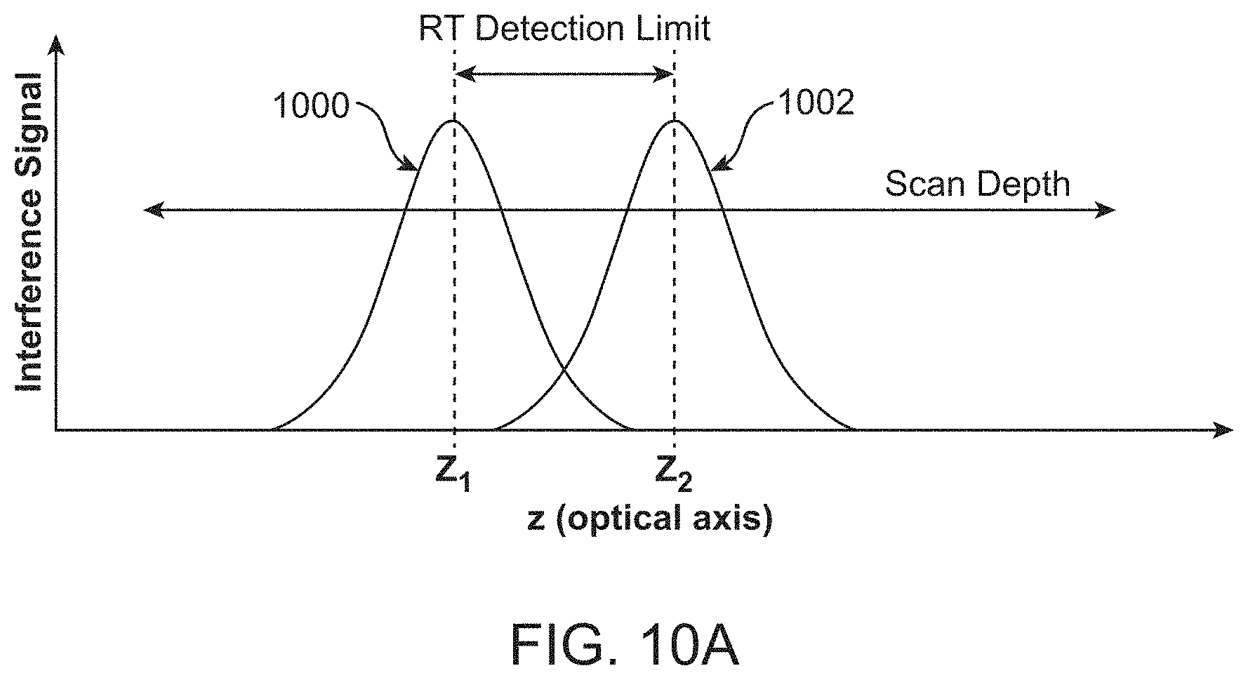
D00017

D00018

D00019

D00020

D00021

D00022

D00023

D00024

D00025

D00026

D00027

D00028

D00029

D00030

D00031

D00032

D00033

D00034

D00035
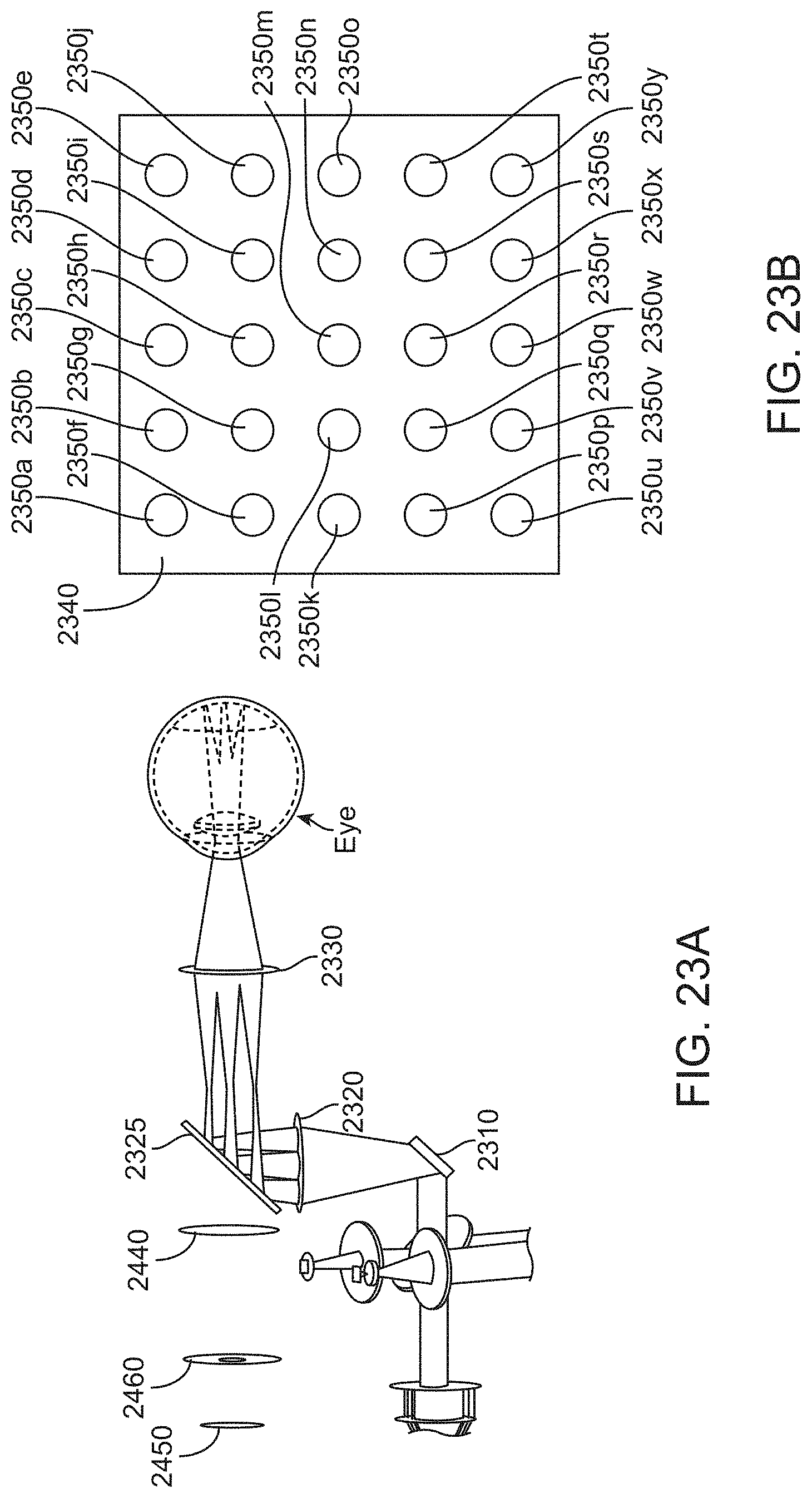
D00036

D00037

D00038

D00039

D00040
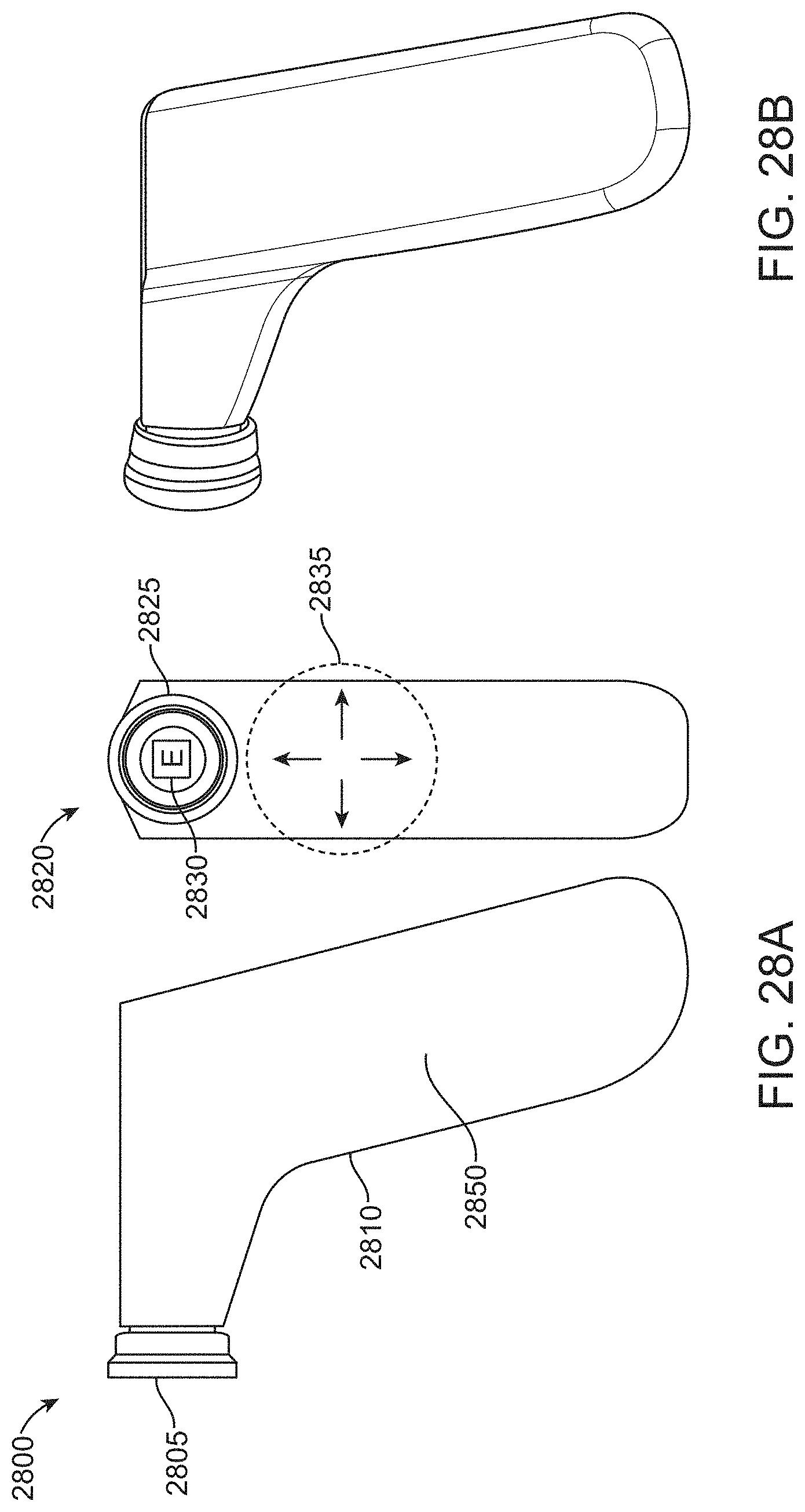
D00041

D00042

D00043

D00044

D00045

D00046

D00047

D00048

D00049

D00050

D00051

D00052

D00053

D00054
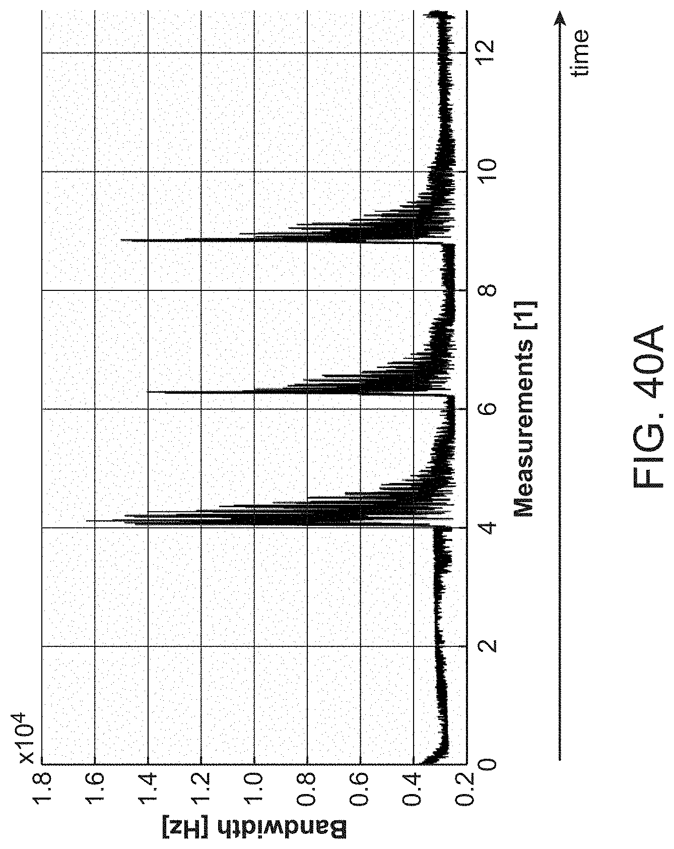
D00055

D00056

D00057
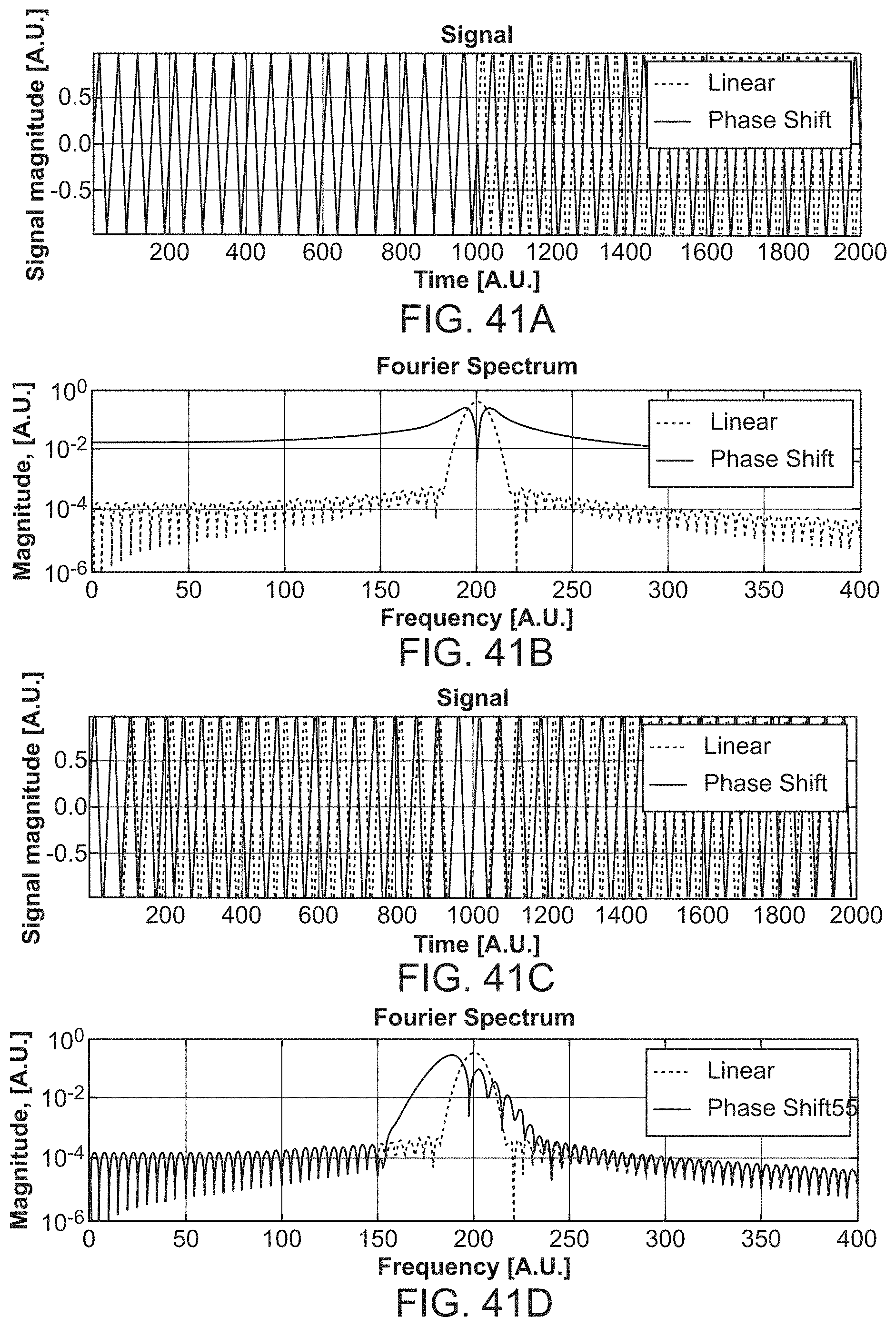
D00058
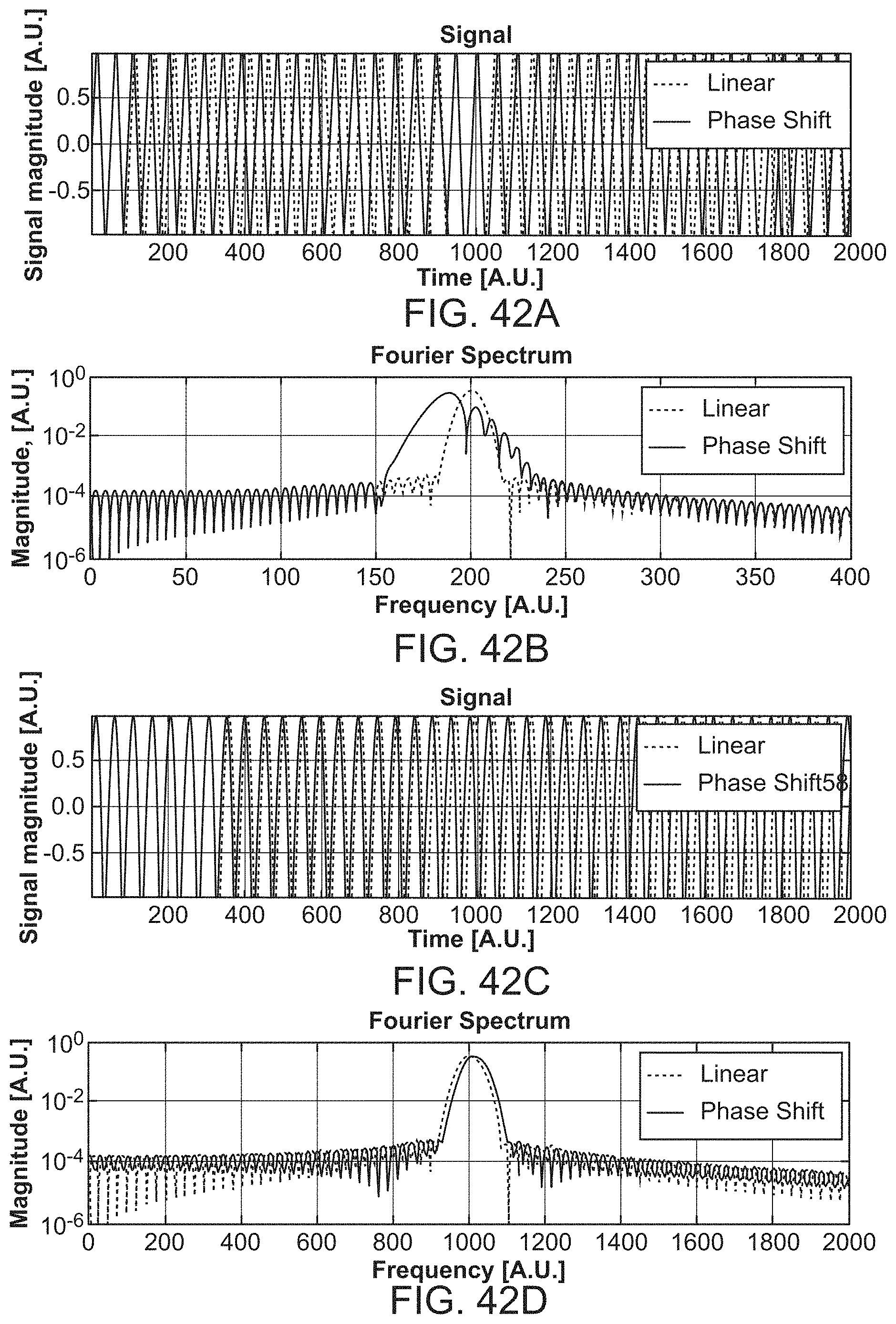
D00059
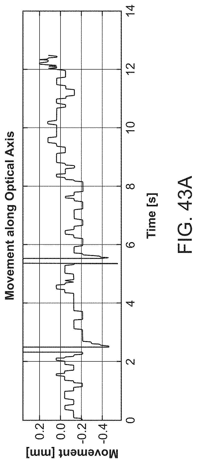
D00060
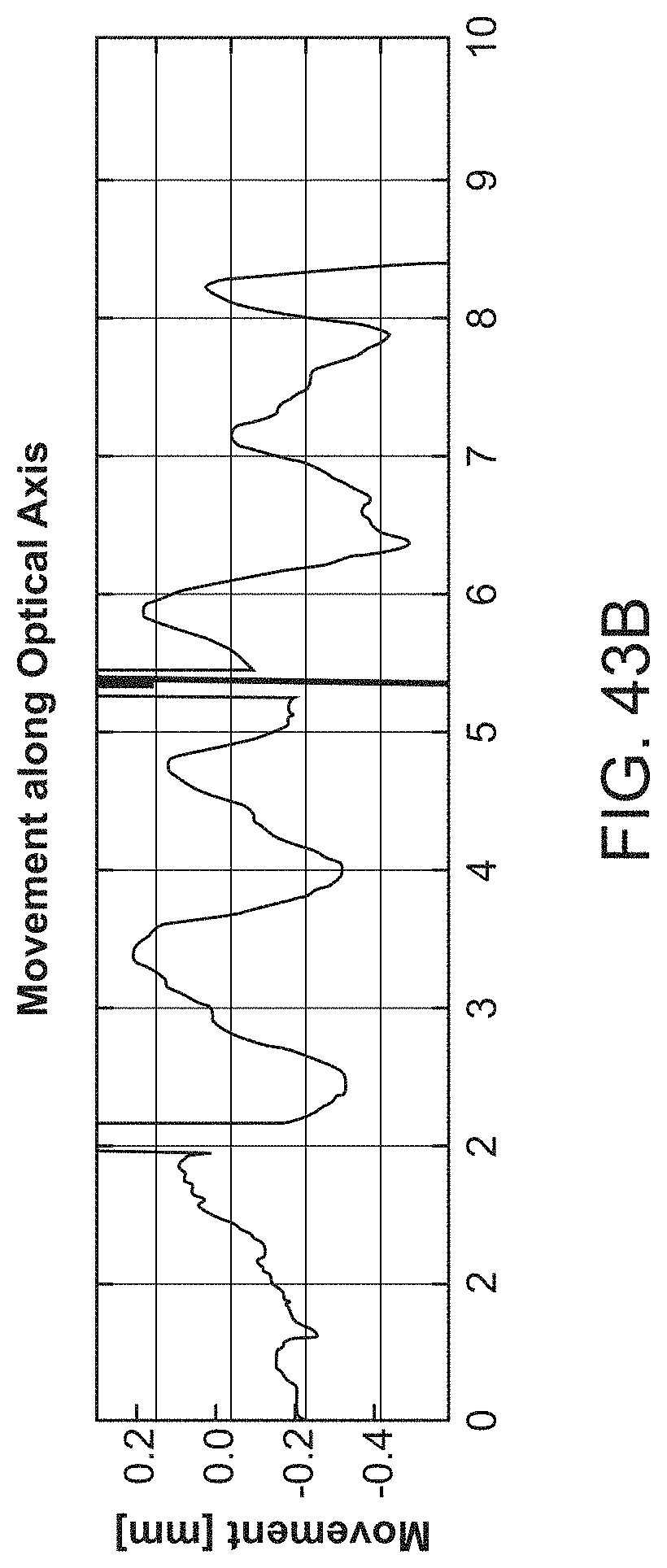


XML
uspto.report is an independent third-party trademark research tool that is not affiliated, endorsed, or sponsored by the United States Patent and Trademark Office (USPTO) or any other governmental organization. The information provided by uspto.report is based on publicly available data at the time of writing and is intended for informational purposes only.
While we strive to provide accurate and up-to-date information, we do not guarantee the accuracy, completeness, reliability, or suitability of the information displayed on this site. The use of this site is at your own risk. Any reliance you place on such information is therefore strictly at your own risk.
All official trademark data, including owner information, should be verified by visiting the official USPTO website at www.uspto.gov. This site is not intended to replace professional legal advice and should not be used as a substitute for consulting with a legal professional who is knowledgeable about trademark law.