Aqua Shoe Having Anti-slip Structure
CHOI; Sun Mi
U.S. patent application number 16/807285 was filed with the patent office on 2020-06-25 for aqua shoe having anti-slip structure. The applicant listed for this patent is GTS GLOBAL CO., LTD.. Invention is credited to Sun Mi CHOI.
| Application Number | 20200196702 16/807285 |
| Document ID | / |
| Family ID | 55539210 |
| Filed Date | 2020-06-25 |


| United States Patent Application | 20200196702 |
| Kind Code | A1 |
| CHOI; Sun Mi | June 25, 2020 |
AQUA SHOE HAVING ANTI-SLIP STRUCTURE
Abstract
The present invention relates to a shoe with a superior wearing sensation that is equipped with an anti-slip structure to forward comfort and safety in a watery place, and more specifically, to an aqua shoe including an upper that covers an instep from above, an insole part that connects to the lower part of the upper and an outsole part which is integrated by adhesion with the insole part and the upper and which is supported by an outsole surface, wherein the outsole part is equipped with an anti-slip structure in which a plurality of suction parts are arranged while a suction part includes a cup that tightly contacts along the cup rim to the ground surface to provide, by being compressed, suction force and a protuberance that protrudes downward from the center of the cup.
| Inventors: | CHOI; Sun Mi; (Gyeonggi-do, KR) | ||||||||||
| Applicant: |
|
||||||||||
|---|---|---|---|---|---|---|---|---|---|---|---|
| Family ID: | 55539210 | ||||||||||
| Appl. No.: | 16/807285 | ||||||||||
| Filed: | March 3, 2020 |
Related U.S. Patent Documents
| Application Number | Filing Date | Patent Number | ||
|---|---|---|---|---|
| 15551473 | Aug 16, 2017 | |||
| PCT/KR2015/002301 | Mar 10, 2015 | |||
| 16807285 | ||||
| Current U.S. Class: | 1/1 |
| Current CPC Class: | A43B 5/08 20130101; A43B 13/122 20130101; A43B 13/226 20130101; A43B 13/223 20130101; A43B 13/184 20130101 |
| International Class: | A43B 5/08 20060101 A43B005/08; A43B 13/22 20060101 A43B013/22; A43B 13/12 20060101 A43B013/12; A43B 13/18 20060101 A43B013/18 |
Foreign Application Data
| Date | Code | Application Number |
|---|---|---|
| Feb 17, 2015 | KR | 10-2015-0024180 |
Claims
1. An aqua shoe that is equipped with an anti-slip structure comprising: an upper that configured to cover an instep from above; an insole part that connects to a lower part of the upper; and an outsole part coupled to the insole part and the upper and having an outsole surface, wherein the outsole part is equipped with the anti-slip structure, the anti-slip structure comprises: a plurality of suction parts are arranged on the outsole surface while a suction part includes a cup that is shaped concave down and configured to make, along a rim of the cup, with the ground surface to provide, by being compressed, suction force; and connections that provided on the outsole surface, each connection coupling neighboring cups to each other; and wherein the outsole part is provided with an inlay that shapes as a flat panel, and the level of the inlay bottom corresponds to the level of the lower end of the suction part.
2. The aqua shoe of claim 1, wherein the suction part further includes a protuberance that protrudes downward from a center of the cup.
3. The aqua shoe of claim 2, wherein the suction part is constructed so that a level of the cup rim is located lower than a level of the lower end of the protuberance.
4. The aqua shoe of claim 3, wherein, for the suction part, the cup rim, upon stepping on the ground, contacts to the ground and provides suction force by being compressed then relieves the suction force when the protuberance, upon shifting the foot load and by increasing the pressure, contacts to the ground.
5. The aqua shoe of claim 1, wherein the anti-slip structure is provided with openings that vertically penetrate between the connections.
6. The aqua shoe of claim 1, wherein the anti-slip structure includes hexagonal outsole units, for which six connections that lie at an equal interval with a suction part as the center connect six suction parts to constitute an outsole unit.
7. The aqua shoe of claim 1, wherein the upper and insole part aforementioned are integrated via the Bonis sewing method by which the upper and the insole part confront each other at their edge.
8. The aqua shoe of claim 1, wherein the outsole part is provided with an inlay that shapes as a flat panel, and the level of the inlay bottom corresponds to the level of the lower end of the suction part.
9. The aqua shoe of claim 8, wherein the outsole part is provided with a side wall that forms edging around the suction part arrangement and openings form among the connections adjacent to the inlay whereas occlusions form among the connections adjacent to the side wall.
10. The aqua shoe of claim 8, wherein the inlay is provided with one or more grooves, and sinks that shape as a ring and are depressed upward.
11. The aqua shoe of claim 8, wherein the area in the inlay that corresponds to the heel, which initially contacts on the ground surface and to which the highest pressure is applied in walking, is provided with a friction area in which a plurality of protuberances.
12. The aqua shoe of claim 1, wherein the anti-slip structure includes hexagonal outsole units, for which six connections that lie at an equal interval with a suction part as the center connect six suction parts to constitute an outsole unit.
13. The aqua shoe of claim 1, further comprising an insert that placed on and removed from a top of the insole, wherein the insert is provided with a plurality of conduits that link up with the openings of the anti-slip structure.
Description
CROSS REFERENCE TO RELATED APPLICATIONS AND CLAIM OF PRIORITY
[0001] This application is a divisional application of U.S. application Ser. No. 15/551,473, filed on Aug. 16, 2017, which is a National Stage entry under 35 U.S.C. .sctn. 371 of International Application No. PCT/KR2015/002301 filed on Mar. 10, 2015, which claims priority to the benefit of Korean Patent Application No. 10-2015-0024180 filed in the Korean Intellectual Property Office on Feb. 17, 2015, the entire contents of which are incorporated herein by reference.
TECHNICAL FIELD
[0002] The present invention relates to a shoe, and more specifically, to an aqua shoe with a superior wearing sensation that is equipped with an anti-slip structure to forward comfort and safety in a watery place.
BACKGROUND ART
[0003] A shoe is to mitigate the shock from walking and protect the pedestrians foot from an external environment, and most people wear it.
[0004] Such a shoe, in general, in order to match up with the shape of a foot, involves an insole part in the lower part of the shoe and an upper in the upper part of the shoe to cover the foot.
[0005] Recently, as customers increasingly take an interest in fashion as well as health, shoes with various types, shapes or materials are proposed. Representative materials for a shoe include leather, fiber and synthetic resin.
[0006] A shoe made of leather maintains its shape relatively well without significant deformation during and after wearing, whereas such a shoe is not very comfortable to wear, frequently sustains damages in the heel or toe depending on ambulatory behaviors and is less effective in ventilation.
[0007] Although a loafer or sneaker made of relatively soft materials such as fiber and synthetic resin offers comfort, it deforms over time and lacks durability.
[0008] Efforts have been made to make up for such drawbacks embedded within a shoe, but it is difficult to meet the requirements simultaneously of convenience of wearing, durability and ease of walking as of this moment.
[0009] Meanwhile, shoes that are made of relatively thin materials with a high softness are recently sought after for the sake of convenience in a swimming pool, beach and the like.
[0010] However, because these shoes tend to concentrate only on water resistance, wearing sensation may be compromised when water infiltrates into them, and furthermore, because these shoes are usually used in a watery place, safety incidents are introduced caused by slipperiness.
SUMMARY
[0011] Accordingly, to solve those problems aforementioned, the present invention provides an aqua shoe equipped with an anti-slip structure that facilitates sweat and water explusion as well as forwards walking safety on a watery surface.
[0012] In order to achieve the objectives, the present invention provides an aqua shoe including an upper that covers an instep from above, an insole part that connects to the lower part of the upper and an outsole part which is integrated with the insole part and the upper and which is supported by an outsole surface, wherein the outsole part is equipped with an anti-slip structure in which a plurality of suction parts are arranged while a suction part includes a cup that tightly contacts along the cup rim to the ground surface to provide, by being compressed, suction force and a protuberance that protrudes downward from the center of the cup, which forwards safety and convenience in activities in a watery place.
[0013] The suction part aforementioned may be required to be constructed so that the level of the cup rim should be located lower than the level of the lower end of the protuberance.
[0014] For the suction part, the cup rim, upon stepping on the ground, contacts to the ground and can provide suction force by being compressed then can relieve the suction force when the protuberance, upon shifting the foot load and by increasing the pressure, contacts to the ground.
[0015] The outsole part aforementioned may be provided with connections that link the tops of the suction part one another and openings that vertically penetrate between the connections, the structure of which therefore ameliorates water expulsion.
[0016] The outsole part is provided with an inlay that shapes as a flat panel and lies forward-backward across the outsole part carrying a plurality of tributaries that bilaterally extend, wherein the level of the inlay bottom may correspond to the level of the lower end of the suction part.
[0017] The outsole part is provided with a side wall that forms edging around the suction part arrangement and, furthermore, openings may form among the connections adjacent to the inlay whereas occlusions may form among the connections adjacent to the side wall, which allows rigidity to be juxtaposed with water expulsion.
[0018] In addition, the outsole part may include hexagonal outsole units, wherein six connections that lie at an equal interval with a suction part as the center connect six suction parts to constitute an outsole unit, which may provide even suction force.
[0019] The upper and insole part aforementioned may be required to be integrated via the Bonis sewing method by which the upper and the insole part confront each other at their edge.
[0020] Moreover, the aqua shoe may further include a web part that extends forward from the outsole part front and may push against the stream in the water.
[0021] Being made of light materials and manufactured via streamlined processes, a shoe according to the present invention improves productivity and fits to the shape and motion of a foot.
[0022] In addition, a shoe according to the present invention may forward safety by exploiting suction force in order to prevent slipperiness in a watery place and maximizes convenience of use by exploiting a structure that may relieve the suction force depending on pressure change during ambulatory behaviors.
BRIEF DESCRIPTION OF DRAWINGS
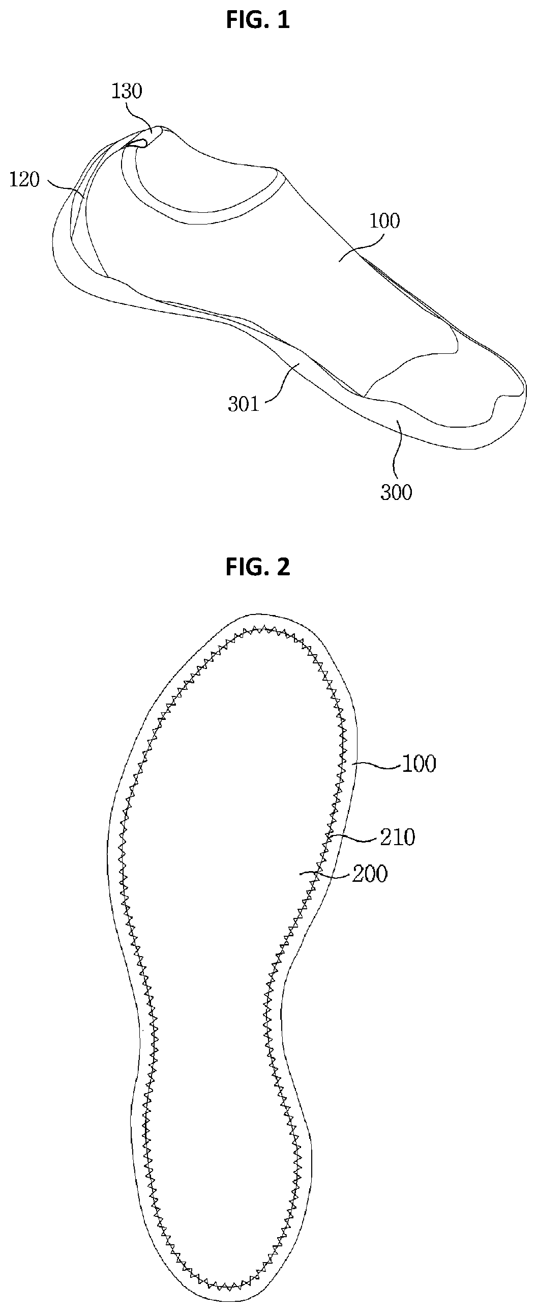
[0023] FIG. 1 is a perspective view of an aqua shoe that is equipped with an anti-slip structure according to the present invention.
[0024] FIG. 2 is a bottom view that illustrates the integration of an upper and an outsole part of an aqua shoe that is equipped with an anti-slip structure according to the present invention.
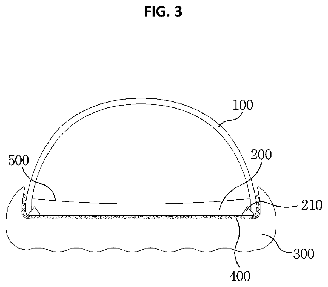
[0025] FIG. 3 is front cross-sectional view of an aqua shoe that is equipped with an anti-slip structure according to the present invention.
[0026] FIG. 4 is a bottom view of an aqua shoe that is equipped with an anti-slip structure according to a first embodiment of the present invention.
[0027] FIG. 5 is a bottom view of an aqua shoe that is equipped with an anti-slip structure according to a second embodiment of the present invention.
[0028] FIG. 6 is a bottom view of an aqua shoe that is equipped with an anti-slip structure according to a third embodiment of the present invention.
[0029] FIG. 7 is a top view of an unclosed side of an aqua shoe that is equipped with an anti-slip structure according to the present invention.
[0030] FIG. 8 is a bottom view of an embodiment of an insert of an aqua shoe that is equipped with an anti-slip structure according to the present invention.
DETAILED DESCRIPTION
[0031] The present invention will be more specifically described hereinafter with reference to the accompanying drawings to illustrate an aqua shoe that is equipped with an anti-slip structure according to the present invention.
[0032] An aqua shoe of the present invention means a shoe that is flexible, fits well to a foot and possesses, as undermentioned, a structure to prevent slipperiness and another structure to expel water to be used in a watery place such as small stream, swimming pool, beach and the like. The present invention defines, based on functional semantics in consideration of the use in a watery place by employing the term of "aqua" that means water, an aqua shoe that is provided simultaneously with water resistance on the top side, water expulsion on the bottom side and suction also on the bottom side.
[0033] An aqua shoe that is equipped with an anti-slip structure according to the concept of the present invention basically includes an outsole part on the bottom side that is provided with a suction structure to prevent slipperiness on the ground surface, an upper that covers from above the outsole part and an insole part that is integrated via sewing with the upper and, on the bottom side, assembled via adhesion with the top surface of the outsole part.
[0034] The outsole part may be, according to a shoe type, constructed in various shapes and dimensions and, should the thoughts of the present invention be applied, is not limited to the description and drawings as undermentioned. In the present invention, should a person normally stand putting the feet together, the sides that confront each other are defined as the inside/inward whereas the other, opposite sides are defined as the outside/outward.
[0035] The use of an aqua shoe that is equipped with an anti-slip structure according to the present invention is not limited to the application aforementioned.
[0036] FIG. 1 is a perspective view of an aqua shoe that is equipped with an anti-slip structure according to an embodiment of the present invention and FIG. 2 is a bottom view thereof.
[0037] The present invention basically includes, going down from the top side, an upper 100, an insole part 200 and an outsole part 300.
[0038] The outsole part 300 supports, on the top surface, the sole and contacts, on the bottom side, to the ground surface while the materials for the outsole part 300 may include, in order to ameliorate friction, natural rubbers or synthetic rubbers, but not limited thereto.
[0039] In view of the fact that the thoughts of the present invention provide shoe materials in general lighter than previous ones, the materials for the outsole part 300 may be determined among synthetic resins, TPEs(thermoplastic elastomers), natural rubber, synthetic rubbers and the like that can be injection-molded.
[0040] In view of the fact that the outsole part 300 may be required to support the entire shoe structure and possess a durability higher than the durability of other parts, the outsole part 300 has a thickness larger than the thickness of the upper 100 and the insole part 200.
[0041] In addition, the outsole part 300 can be classified in large into an outsole that steps on the ground and a side wall that surrounds the lower flank surface of the upper 100 and the side wall may be formed with vertical elevations and depressions to secure reinforcement for a light shoe.
[0042] The outsole part 300 according to the present invention includes on the bottom side a structure for suction, which may be a kind of vacuum suction cup, in order to forward activity and safety on a watery or slippery surface, one of the preferred embodiments of which will be described following FIG. 4.
[0043] The upper 100 takes a form as if the upper 100 entirely encloses the instep and ball and may be provided with an unclosed area (reference numeral undesignated), wherein, in the light of the thoughts of a light shoe the present invention provides, the materials for the upper 100 may be required to be determined among light ones with a high expansion coefficient and, in this respect, Neoprene and Polyspan may be selected for the upper materials.
[0044] Because the upper 100 is to fit better, due to the expansion, to the instep and ball and because the upper 100 organically and flexibly deforms as the foot deforms during ambulatory behaviors, which ameliorates the unity of the shoe with the foot.
[0045] The upper 100 is integrated preferentially with the insole part 200 without being involved in a manufacturing process that integrates the upper 100 directly with the outsole part 300, which is exhibited in FIG. 2 that illustrates an integration of the upper with the insole part.
[0046] With reference to the thoughts of the present invention, in order to forward lightness and rigid integration, following integrating the upper 100 with the insole part 200 via sewing, the bottom surface of the insole part adheres to the top surface of the outsole part 300, then the lower flank outside surface of the upper 100 adheres to the side wall inside surface of the outsole part 300.
[0047] With reference to FIG. 2 for more details, the lower end area of the upper 100 is sewn to the insole part 200 along the outside periphery of the insole part 200.
[0048] Existing methods for manufacturing outer socks in general turn an upper inside out so that the inside surface of the upper faces outward, turn the outsole upside down that corresponds to an insole part of the present invention, confront and sew the lower end area outside peripheral surface of the upper with the bottom surface outside peripheral area of the outsole, then turn the upper inside out so that the sewn surface is not revealed outward.
[0049] The technique in the existing methods to integrate an upper and an outsole has been decent in that the outside termination is to a certain extent flawless whereas a few problems have also been enumerated for such a technique in that sewn edge protrudes to impair wearing sensation posing injuries in the sole or ball as the case may be and the applicable manufacturing processes are complicated.
[0050] In this regard, the present invention recommends the One Piece Pattern, so called Bonis process, as an integration method to sew an upper 100 to an insole part 200, wherein the upper 100 and the insole part 200 are aligned so that the lower end edge of the upper 100 are to be adjacent to the outside peripheral edge of the insole part 200 and the adjacent areas laid down on a plane are sewn up-down and zigzag by means of sewing yarn, which allows the integration of the upper 100 with the insole part 200 to be completed in a single sewing process with advantageous effects in that the manufacturing processes have been further streamlined compared with existing methods and there exists no height difference or protrusion that may impair wearing sensation in the transition area that may impact the foot.
[0051] The integrated area in which the upper 100 is sewn to the insole part 200 should be defined as a transition area 210 that adheres to the inside peripheral area of the outsole part 300, as undermentioned, to prevent exposure externally.
[0052] Meanwhile, materials with a superior wearing sensation may be selected for the insole part 200 because the insole part 200 directly contacts to the sole of the foot. Those materials provided, in consideration of absorption or expulsion of sweat or water, with a plurality of pores or penetrating holes may be selected for the insole part 200, for which synthetic materials in mesh structure are selected, but not limited thereto. The mesh structure may take various forms in consideration of sole sensation as well as the expulsion or absorption properties. As undermentioned, such a mesh structure, together with openings 330 in the outsole part 300 and conduits in an insert that is to be addedly provided, provides a function of water expulsion.
[0053] Because the upper 100 and the insole part 200 adhere to the outsole part 300 and because light materials are applied thereto, the entire support properties by means of the outsole part 300 should be ameliorated.
[0054] To achieve the objective, the outsole part 300 may include an outsole and a side wall, wherein the side wall may be formed with vertical elevations and depressions.
[0055] As illustrated in FIG. 1, the side wall of the outsole part 300 may include an elevation that extends upward from the toe and another elevation that extends upward from the heel.
[0056] The elevations and depressions of the outsole part 300 maintain the shoe form even in a light shoe and allow the shoe to organically deform as the body naturally changes the form, which forwards wearing sensation as well as durability.
[0057] In consideration of the durability aforementioned, in the invention, a front upper (reference numeral undesignated) as well as a rear upper 120 may be added to the upper 100.
[0058] In view of the fact that the upper 100 is made of materials with a high expansion coefficient, the front upper and rear upper 120 play a role in restricting expansion to a certain extent in the location subject to a high strength and in increasing resistance against external impact, wherein the materials for the front upper and the rear upper may be required to be harder than those for the upper 100. For example, when the upper 100 is made of Neoprene, the front upper and the rear upper 120 may be made of fabric, leather, synthetic fiber and the like.
[0059] The front upper is provided, where the 3rd toe lies, with a flexure that curves down forward while the back end of the front upper may draw a line that fluctuates as the center arcs of a Taiji symbol do, wherein the flexure skews outward because the great toe is materially and significantly wider than other toes.
[0060] The rear upper 120 minimizes the backward deformation upon putting on and taking off the shoe and reinforces the shoe against the load on the heel while the front upper increases the resistance against the toe lift especially during ambulatory behaviors and against external impact.
[0061] Meanwhile, the rear upper 120 may extend, in large, from the outsole part 300 vertically to the unclosed area of the upper 100 while an extension 130 further protruding to the upside may be added to the upper end of the rear upper 120.
[0062] The extension 130 may be grabbed by a hand and facilitate putting on and taking off the shoe.
[0063] The extension 130 is integrated to a body with the rear upper 120 and may be required, as the front upper is, to be sewn at the top surface of the upper 100 but other various integration methods are not to be restricted including adhesion and thermal bonding.
[0064] The rear upper 120 also supports, as the front upper does, the backward of the upper 100 that is made of soft materials and, in consideration of durability, the rear upper 120 is preferably widest laterally at the lower end.
[0065] As aforementioned, an extension 130 may be integrated to the top end of the rear upper 120 that is manually grabbable while, for the sake of integration with the upper 100, a backward sewing area may be formed, in which the sewing yarn penetrates forward-backward.
[0066] The front upper and the rear upper 120 are integrated by being sewn prior to the integration of the upper 100 with the insole part 200, wherein, if the integration is based on the transition area 210, both the front upper and the rear upper may be integrated via sewing, especially via the Bonis sewing method.
[0067] Meanwhile, a ring 140 shown in FIG. 7 may be added to the unclosed area in the upper 100 through which a foot enters and exits in order to prevent damages caused by repeated use and which encloses the upper end of the upper.
[0068] FIG. 3 illustrates a front cross-sectional view of a light shoe according to the present invention, more specifically, a forward section that has been cut laterally at a position around which the 2nd elevation is located.
[0069] As aforementioned, after an upper 100 is integrated to an insole part 200 with both edges are aligned adjacent to each other, across a transition area 210 and via a sewing method including the Bonis sewing method, on the bottom surface of the insole part 200 and on the lower end outside periphery of the upper 100 is applied adhesion zone 400 that may be a adhesive whereas the adhesion zone 400 may also be formed by being applied on the upper end of the outsole part 300 or, together both with the upper 100 and the insole part 200 on the outsole part 300.
[0070] Accordingly, the insole part 200 adheres to the outsole part 300 via the adhesion zone 400 while the upper 100 adheres to the outsole part 300 also via the adhesion zone 400, in which the bonding strength further increases at the transition area 210 between the insole part 200 and the upper 100.
[0071] Here, the outsole part 300 adheres to the upper 100 at each elevation because the adhesion zone 400 is formed on the inside surface of the elevations.
[0072] An insert 500 may be added over the top of the insole part 200 in order to forward shock absorption and wearing feel while the insert 500 may contact directly to the sole and provide water expulsion, the description of which will follow.
[0073] Moreover, a reinforcement part (not illustrated) may be integrated on the outside surface of the upper 100 in order to appropriately support the shoe structure against repeated deformation.
[0074] The reinforcement part can act as a pre-determined skeleton, on which pre-determined pattern may form, that may be previously made of synthetic materials then be sewn, adhered or thermally bonded to the outside surface of the upper 100.
[0075] The reinforcement part, as a pre-determined concavo-convex form, may be arranged on the upper 100 and is preferably constituted by the foam textile printing method to increase aesthetics and secure the function of reinforcement.
[0076] Polyurethane foam may be selected for the foam textile printing aforementioned and constructed on the upper 100 prior to integrating the upper 100 with the insole part 200.
[0077] For example, the reinforcement part is built up by injection printing materials into the mold that covers the surface to be printed on the textile of the upper 100, in which the foam ink injected forms solid geometry that grows, by means of a press machine, to a uniform or otherwise desired thickness.
[0078] The reinforcement part may be arrange on the shoe both up-down and forward-backward, wherein the up-down reinforcement, as a vertical reinforcement section, resists against up-down tension while the forward-backward reinforcement section that has been bent forward-backward to exhibit a pre-determined thickness resists forward-backward tension.
[0079] The upper 100 according to the present invention is made of materials with a high expansion coefficient that is superior in tightness on and integration to the foot but not appropriated to intense activities, the drawbacks of which can be countered by means of the reinforcement part.
[0080] FIG. 4 is a bottom view of an aqua shoe that is equipped with an anti-slip structure according to a first embodiment of the present invention.
[0081] Although embodiments are illustrated with reference to the each respective bottom view, it should be emphasized that the embodiments are described taking into consideration a state in which a shoe is worn, as depicted in FIG. 1, and the outsole part 300 steps on the ground surface.
[0082] As aforementioned, being used in a watery place such as swimming pool, an aqua shoe according to the present invention may be required to be provided with a pre-determined friction for the sake of due safety and activity and the friction can be applied by means of vacuum suction.
[0083] Accordingly, the outsole part 300 may be equipped with a plurality of suction parts 310 on the outsole surface 303 while a suction part 310 shapes as a cup that is concave down and performs vacuum suction.
[0084] Upon applying the body weight on the sole, the suction part 310 discharges the internal air by expanding to the cup rim then being compressed downward, which generates inside the suction part 310 a negative pressure that gives suction force, which may increase due to water film created on the ground surface, to attach to the ground surface.
[0085] Because any suction force that sustains may impose discomfort on walking, the suction part 310 may be provided with an additional structure to relieve the suction force, which will be described below.
[0086] In the bottom view, the suction parts 310 shape as circles and are connected each other via a connection 320 while an opening 330 may form among the connections 320 through which water is expelled from the insole part 200 and the insert.
[0087] The suction parts 310 and the connections 320 can be selectively arrayed and it may be required that suction parts 310 should form a regular hexagon with a single suction part 310 as the center to provide uniform suction force and to correspond to diverse types and shapes of shoes.
[0088] In other words, six connections 320 radially extend from a single suction part 310 at an equal interval and another suction part 310 bonds to each of the connections, for which the suction parts are connected via the connections 320 so that any two adjacent suction parts surrounding a single suction part constitute a side of the regular hexagon
[0089] Following the rule, from a single suction part 310 six connections 320 radially extend to which six suction parts bond, which constructs a single outsole unit 302. Any of the suction parts 310 can constitute outsole units 302 pertinent to it in this way and adjacent outsole units 302 share an overlap on the bottom.
[0090] The geometry of the connection 320 can be selectively determined while it may be required that the connection should get wider as the connection get closer to the suction part 310.
[0091] In the first embodiment according to the present invention, the opening 330 generated in the middle of three connections 320 roughly shapes as a triangle.
[0092] The side wall 301 may extend from the outsole as if the side wall 301 encloses the bottom surface outside periphery of the outsole part 300, and may act as a skeleton of the outside bottom surface, wherein the array of the outsole units 302 contacts to the side wall 301, the structure of which may be required to be injection-molded as an integrated product.
[0093] Details will be specified regarding the structure of the suction part.
[0094] Because the area that contacts to the ground surface may correspond mostly to the suction parts 310, it may be required that the suction parts 310 should protrude downward below the connection 320.
[0095] Accordingly, the connections 320 link the tops of the suction parts 310 while a suction part 310 includes a concave down cup 311. The cup 311 provides suction force by generating vacuum pressure, as aforementioned, between the internal space of the cup and the ground surface.
[0096] However, the suction force should be relieved to ease the vacuum pressure-caused walking discomfort. To relieve the suction force, the present invention recommends another structure that can be a protuberance 312 that protrudes downward from the center of the cup 311.
[0097] It is preferable to render the cup 311 rim extend downward below the protuberance 312. When the pre-determined area of the outsole part 300 steps, during ambulatory behaviors, on the ground surface, the cup 311 tightly contact to the ground surface at the rim and, being compressed, deforms discharging the air inside the cup, which generates suction force between the bottom side of the cup 311 and the ground surface. Upon a higher pressure applying, the protuberance 312 located at the center of the cup 311 moves downward, contacts to the ground surface, compresses the residual air inside the cup 311 then expels the air to push away the ground surface, which relieves the suction force.
[0098] In view of the fact that water film generated when a shoe bottom initially contacts to the watery ground surface causes slipperiness, this structure is to render, over the course where a shoe continue to contact to and apply compression to the ground, the cup 311 generate suction force when the shoe contacts to and applies the initial compression to the ground and the protuberance 312 move downward further to organically relieve the suction force when the load shifts for walking to the area of the shoe bottom that contacts to the ground.
[0099] The connections 320 link the suction parts 310 one another in order to maintain the array of the suction parts by organically being deformed and twisted and, at the same time, organically change the form of the shoe bottom in order to generate uniform suction force by maintaining the form of each suction part 310.
[0100] The opening 330 may act as a temporary reservoir that contains a certain volume of water to prevent an excessive water film from being created between the ground surface and the cup 311 when the shoe contacts to the ground and generates suction force.
[0101] FIG. 5 is a bottom view of an aqua shoe that is equipped with an anti-slip structure according to a second embodiment of the present invention.
[0102] If, as in the first embodiment of the present invention, the outsole units 302 are arranged in the entire bottom and the openings 330 forms among the connections 320 that constitute the outsole units 302, strength or support may be impaired although overall flexibility may increase.
[0103] To solve the problem, in the second embodiment according to the present invention is proposed a structure that distributes an inlay 350 as an enforcement to increase support.
[0104] The inlay 350 may lie roughly forward-backward across the outsole carrying a pre-determined number of tributaries, around and among which the suction parts 310 may be distributed.
[0105] It may be required that the inlay 350 should shape roughly as a flat panel while the level of the inlay bottom should correspond to the level of the cup 311 rim of the suction part 310, the geometry of which facilitates generating suction force in the suction part 310 when downward pressure compresses the inlay 350.
[0106] The inlay 350 may be provided, in certain areas in the inlay, with one or more grooves 351 and sinks 352 that shape as a ring and are depressed upward. The grooves 351 and sinks 352 act as a reservoir to temporarily retain water and minimize the effect of water film created in the inlay 350 that shapes as a flat panel.
[0107] The area in the inlay 350 that corresponds to the heel, which initially contacts on the ground surface and to which the highest pressure is applied in walking, may be required to be provided with a friction area 370 in which a plurality of protuberances.
[0108] The openings 330 that are vacant among the connections 320 and occlusions 340 that are filled among the connections 320 may be selectively arranged in this embodiment of the present invention, wherein the occlusions 340 may support the connection even more rigidly among the connections 320 so that the overall form of the outsole part is maintained better.
[0109] Although the arrangement of the openings 330 and the occlusions 340 may be selectively determined, it is preferable to distribute the openings 330 in the proximity of the inlay 350 in order to facilitate water expulsion and minimize water film and distribute the occlusions 340 in the proximity of the side wall 301 in order to secure rigidity.
[0110] FIG. 6 is a bottom view of an aqua shoe that is equipped with an anti-slip structure according to a third embodiment of the present invention.
[0111] Repeated description will be omitted regarding the suction parts 310 and the inlay 350.
[0112] As aforementioned, an aqua shoe according to the present invention may maximize the applicability in a place such as swimming pool and beach where people enjoy water activities. Description will follow regarding a structure equipped with a web part 360 in order to push against the stream from the outsole part 300 front and to ameliorate the effectiveness of water activities according to the third embodiment of the present invention.
[0113] The web part 360 extends forward from the outsole part 300 front and, as illustrated, being worn by a user's foot, secures a pre-determined volume of water forward for the user to push away.
[0114] Preferably, the web part 360 may be required to curve upward to forward water expulsion.
[0115] In addition, the web part 360 may be provided with one or more reinforcement rib(s) 361 to prevent the web part 360 from deforming to a certain extent, wherein the vertical thickness of the reinforcement rib 361 may be larger than the thickness of the rest of the web part 360.
[0116] The web part 360 is preferable to be injection-molded as a single product integrated with the outsole part 300.
[0117] FIG. 7 is a top view of an unclosed side of an aqua shoe that is equipped with an anti-slip structure according to the present invention.
[0118] The upper 100 and the insole part 200 are integrated at the transition area 210 via the Bonis sewing method preventing any height difference while on the top side of the upper 100 forms a ring 140 which ameliorates durability and feel during putting on and taking off the shoe.
[0119] The ring 140 may be integrated with the upper 100 via sewing.
[0120] In addition, the insole part 200 may be made of materials in a mesh structure or with a plurality of pores to secure water expulsion, in the case of which the internal water may be expelled through the openings 330 of the outsole part 300 but an insert may be additionally placed on the top of the insole part 200 in order to forward shock absorption or wearing feel.
[0121] FIG. 8 is a bottom view of a preferred embodiment of the insert.
[0122] The insert may be placed on and removed from the top of the insole 200 and may be provided with a plurality of conduits 510 that link up with the openings 330 of the outsole part 300, the geometry, dimension and array of which may be selectively determined.
[0123] It may be preferable to provide with conduit channel(s) 520 that penetrate among the conduits 510 to forward water expulsion in the bottom side while such a conduit channel may constitute a pre-determined bottom pattern.
[0124] The insert 500 may be provided, in the central area of the insert, with friction protuberances 530 that protrude downward in order to give friction against the insole part 200.
[0125] With an upper, insole part and outsole part being made of light materials and with a structure that may streamline the manufacturing processes, an aqua shoe that is equipped with an anti-slip structure according to the present invention forwards productivity and fits in an optimized way to the geometry and motion of a foot
[0126] In addition, an aqua shoe according to the present invention forwards safety via suction force that prevents slipperiness in a watery place and maximizes the convenience of use via a structure that relieves the suction force according to the pressure change during ambulatory behaviors.
[0127] The present invention has been descried thus far with reference to embodiments and accompanying drawings. However, the embodiments and drawings demonstrated are not to restrict but to expound the technical thoughts of this invention while the scope of the technical thoughts of this invention shall not restricted within such examples. The scope of the protection for this invention should be interpreted based on the claims as follows.
* * * * *
D00000
D00001
D00002
D00003
D00004
D00005
D00006
XML
uspto.report is an independent third-party trademark research tool that is not affiliated, endorsed, or sponsored by the United States Patent and Trademark Office (USPTO) or any other governmental organization. The information provided by uspto.report is based on publicly available data at the time of writing and is intended for informational purposes only.
While we strive to provide accurate and up-to-date information, we do not guarantee the accuracy, completeness, reliability, or suitability of the information displayed on this site. The use of this site is at your own risk. Any reliance you place on such information is therefore strictly at your own risk.
All official trademark data, including owner information, should be verified by visiting the official USPTO website at www.uspto.gov. This site is not intended to replace professional legal advice and should not be used as a substitute for consulting with a legal professional who is knowledgeable about trademark law.