Pilot Sending And Receiving Method And Device
WANG; Donghao ; et al.
U.S. patent application number 16/608201 was filed with the patent office on 2020-06-18 for pilot sending and receiving method and device. The applicant listed for this patent is DATANG MOBILE COMMUNICATIONS EQUIPMENT CO., LTD. Invention is credited to Jinxi SU, Donghao WANG.
| Application Number | 20200195400 16/608201 |
| Document ID | / |
| Family ID | 63917989 |
| Filed Date | 2020-06-18 |


| United States Patent Application | 20200195400 |
| Kind Code | A1 |
| WANG; Donghao ; et al. | June 18, 2020 |
PILOT SENDING AND RECEIVING METHOD AND DEVICE
Abstract
Disclosed in the present application are a pilot sending and receiving method and device, configured to reduce a delay of receiving pilot data at a terminal, thus improving efficiency of channel estimation based on the pilot data. The pilot sending method provided in the present application comprises: determining a pilot data pattern configured for a user equipment device, the pilot data pattern comprising time-frequency position information of pilot data, and the time-frequency position information comprising position information of an initial time point of the pilot data in a subframe; and sending to the user equipment device, according to the pilot data pattern, the pilot data.
| Inventors: | WANG; Donghao; (Beijing, CN) ; SU; Jinxi; (Beijing, CN) | ||||||||||
| Applicant: |
|
||||||||||
|---|---|---|---|---|---|---|---|---|---|---|---|
| Family ID: | 63917989 | ||||||||||
| Appl. No.: | 16/608201 | ||||||||||
| Filed: | January 23, 2018 | ||||||||||
| PCT Filed: | January 23, 2018 | ||||||||||
| PCT NO: | PCT/CN2018/073804 | ||||||||||
| 371 Date: | October 25, 2019 |
| Current U.S. Class: | 1/1 |
| Current CPC Class: | H04L 5/0005 20130101; H04L 5/0048 20130101; H04W 72/0446 20130101; H04L 5/0094 20130101; H04L 25/0226 20130101; H04L 5/00 20130101 |
| International Class: | H04L 5/00 20060101 H04L005/00; H04L 25/02 20060101 H04L025/02; H04W 72/04 20060101 H04W072/04 |
Foreign Application Data
| Date | Code | Application Number |
|---|---|---|
| Apr 25, 2017 | CN | 201710278122.0 |
Claims
1. A method for sending a pilot, comprising: determining a pilot pattern configured for a user equipment, wherein the pilot pattern comprises time-frequency position information of the pilot, and the time-frequency position information of the pilot comprises position information of an initial time point of the pilot in sub-frames; and sending the pilot to the user equipment according to the pilot pattern.
2. The method according to claim 1, wherein the time-frequency position information of the pilot comprises position information of the initial time point of the pilot in each of the sub-frames.
3. The method according to claim 2, wherein the initial time point in each of the sub-frames is a first symbol of each of the sub-frames.
4. The method according to claim 1, further comprising: updating the pilot pattern of the user equipment so that the time-frequency position information of the pilot in the updated pilot pattern comprises position information of the initial time point of the pilot in the sub-frames, and position information of the subsequent time points after the initial time point; and sending the pilot to the user equipment according to the updated pilot pattern.
5. The method according to claim 4, wherein after the pilot pattern is updated for the user equipment, and before the pilot is sent to the user equipment according to the updated pilot pattern, the method further comprises: sending control information to the user equipment to instruct the user equipment to receive the pilot.
6. The method according to claim 5, wherein the control information comprises indication information of the updated pilot pattern.
7. The method according to claim 4, wherein updating the pilot pattern for the user equipment comprises: updating the pilot pattern for the user equipment according to a coherence period of time and a coherence bandwidth of a user channel.
8. A method for receiving a pilot, comprising: receiving a pilot at an initial time point in a sub-frame; and determining channel estimation of the sub-frame using the pilot.
9. The method according to claim 8, further comprising: receiving control information to instruct the user equipment to receive the pilot; and receiving the pilot at an initial time point and subsequent time points after the initial time point in the sub-frame according to the control information.
10. An apparatus for sending a pilot, comprising a memory configured to store a computer readable program and a processor configured to execute the computer readable program to: determine a pilot pattern configured for a user equipment, wherein the pilot pattern comprises time-frequency position information of pilot, and the time-frequency position information of the pilot comprises position information of an initial time point of the pilot in sub-frames; and send the pilot to the user equipment according to the pilot pattern.
11. The apparatus according to claim 10, wherein the time-frequency position information of the pilot comprises position information of the initial time point of the pilot in each of the sub-frames.
12. The apparatus according to claim 11, wherein the initial time point in each of the sub-frames is a first symbol of each of the sub-frames.
13. The apparatus according to claim 10, wherein the processor is configured to execute the computer readable program to: update the pilot pattern of the user equipment so that the time-frequency position information of the pilot in the updated pilot pattern comprises position information of the initial time point of the pilot in the sub-frames, and position information of subsequent time points after the initial time point; and send the pilot to the user equipment in the updated pilot pattern.
14. The apparatus according to claim 13, wherein the processor is configured to execute the computer readable program to, after the first device updates the pilot pattern for the user equipment, and before the pilot is sent to the user equipment according to the updated pilot pattern, send control information to the user equipment to instruct the user equipment to receive the pilot.
15. The apparatus according to claim 14, wherein the control information comprises indication information of the updated pilot pattern.
16. The apparatus according to claim 14, wherein the processor is configured to execute the computer readable program to update the pilot pattern for the user equipment according to a coherence period of time and a coherence bandwidth of a user channel.
17. An apparatus for receiving a pilot, the apparatus comprising a memory configured to store a computer readable program and a processor configured to execute the computer readable program to: receive a pilot at an initial time point in a sub-frame; and determine channel estimation of the sub-frame using the pilot.
18. The apparatus according to claim 17, wherein the processor is further configured to execute the computer readable program to: receive control information to instruct the user equipment to receive the pilot; and receive the pilot at the initial time point and subsequent time points after the initial time point in the sub-frame according to the control information.
Description
[0001] This application claims the priority of Chinese Patent Application No. 201710278122.0, filed with the Chinese Patent Office on Apr. 25, 2017, and entitled "A method and apparatus for sending a pilot, and a method and apparatus for receiving a pilot", which is hereby incorporated by reference in its entirety.
FIELD
[0002] The present disclosure relates to the field of communications, and particularly to a method and apparatus for sending a pilot, and a method and apparatus for receiving a pilot.
BACKGROUND
[0003] As the fourth generation of mobile communication technologies is being commercialized at a large scale, and the mobile services are growing constantly, studies have been made on the fifth generation (5G) of communication technologies all over the world. The 5G communication involves a number of technologies, and a variety of demand for data and connectivity services can be satisfied as the technologies are changing and innovating. The Study Item (SI) about standardization of a new 5G air interface has been established in the 71.sup.st RAN session of the 3GPP. The study on the new air interface has been generally made in the following aspects according to the categories of vertical scenarios in the 5G communication: enhanced Mobile Broad Band (eMBB), Ultra-Reliable Low-Latency Communication (URLLC), and massive Machine Type Communication (mMTC).
[0004] In the several application scenarios above, channel encoding, a new multi-access mode, a multi-antenna mode, a new parameter set frame structure, etc., have been discussed in the 3GPP. In the URLLC scenario, there are a number of differences of its service attributes from the legacy data services, so a pertinent study applicable to this scenario shall be made. In order to satisfy the KPI index (a 1 ms delay in uni-directional transmission, and 99.999% transmission reliability) in the URLLC scenario, a study on a new frame structure is important, and a pilot design is important in a design of the new frame structure.
[0005] In an LTE system, channel state information is generally obtained by inserting a number of Reference Signals (RS's) in the time and frequency domains so that a receiver obtains a channel response in the frequency domain by executing estimation and interpolation algorithms on channels in the frequency domain at the positions of the reference signals, where different antenna ports correspond to different reference signals, and their spacing depends upon delays and Doppler spread characteristics of the different channels, so there is a high density of each reference signal in the time and frequency domains. FIG. 1 illustrates a pilot pattern with two antenna ports, where R0 represents a pilot symbol of an antenna port 0, and R1 represents a pilot symbol of an antenna port 1; and 1 represents a symbol index in a timeslot, i.e., a symbol index in the time domain, and k represents an index in the frequency domain. As illustrated in FIG. 1, each row represents symbols in a sub-frame; and for example, each sub-frame includes two timeslots, and each timeslot includes seven symbols, that is, each sub-frame includes 14 symbols.
[0006] In the pilot pattern as illustrated in FIG. 1, in order to obtain a channel response in the frequency domain throughout the sub-frame, a user equipment firstly obtains data of all the pilot symbols, and there is a significant delay in reception; and if a short delay is required for a service in the URLLC scenario, then the pilot design above may not satisfy the delay required of the service. On the other hand, as can be apparent from FIG. 1, when the number of antenna ports is two, there is a pilot overhead (i.e., the number of Resource Elements (REs) occupied by the pilot symbols) of more than 7%, and as the number of antenna ports is increasing, the pilot overhead will be increasing, thus degrading the utilization ratio of an available spectrum in the system.
SUMMARY
[0007] Embodiments of the disclosure provide a method and apparatus for sending a pilot, and a method and apparatus for receiving a pilot so as to shorten a delay in receiving the pilot by a user equipment to thereby improve the efficiency of estimating a channel based upon the pilot.
[0008] An embodiment of the disclosure provides a method for sending a pilot, the method including:
[0009] determining a pilot pattern configured for a user equipment, wherein the pilot pattern includes time-frequency position information of the pilot, and the time-frequency position information of the pilot includes position information of an initial time point of the pilot in sub-frames; and sending the pilot to the user equipment according to the pilot pattern.
[0010] With this method according to the embodiment of the disclosure, the user equipment can obtain the pilots throughout each sub-frame as early as possible using the prepositive pilots (the pilot at the initial time point in the sub-frame) directly instead of waiting until pilots at subsequent time points after the initial time point in the sub-frame are received, to thereby shorten a delay in receiving the pilots, and perform channel estimation using these pilots to thereby shorten a delay in channel estimation.
[0011] In one embodiment, the time-frequency position information of the pilot includes the position information of the initial time point of the pilot in each of the sub-frames.
[0012] In one embodiment, the initial time point in each of the sub-frames is the first symbol of each of the sub-frames.
[0013] In one embodiment, the method further includes:
[0014] updating the pilot pattern of the user equipment so that the time-frequency position information of the pilot in the updated pilot pattern includes position information of the initial time point of the pilot in the sub-frames, and position information of subsequent time points after the initial time point; and
[0015] sending the pilot to the user equipment according to the updated pilot pattern.
[0016] In one embodiment, after the pilot pattern is updated for the user equipment, and before the pilot is sent to the user equipment according to the updated pilot pattern, the method further includes:
[0017] sending control information to the user equipment to instruct the user equipment to receive the pilot.
[0018] In one embodiment, the control information includes indication information of the updated pilot pattern.
[0019] In one embodiment, updating the pilot pattern for the user equipment includes: updating the pilot pattern for the user equipment according to a coherence period of time and a coherence bandwidth of a user channel.
[0020] An embodiment of the disclosure provides a method for receiving a pilot, the method including:
[0021] receiving a pilot at an initial time point in a sub-frame; and
[0022] determining channel estimation of the sub-frame using the pilot.
[0023] In one embodiment the method further includes:
[0024] receiving control information to instruct the user equipment to receive the pilot; and
[0025] receiving the pilot at the initial time point and subsequent time points after the initial time points in the sub-frame according to the control information.
[0026] An embodiment of the disclosure provides an apparatus for sending a pilot, the method including:
[0027] a first device configured to determine a pilot pattern configured for a user equipment, wherein the pilot pattern includes time-frequency position information of the pilot, and the time-frequency position information of the pilot includes position information of an initial time point of the pilot in sub-frames; and
[0028] a second device configured to send the pilot to the user equipment according to the pilot pattern.
[0029] In one embodiment, the time-frequency position information of the pilot includes the position information of the initial time point of the pilot in each of the sub-frames.
[0030] In one embodiment, the initial time point in each of the sub-frames is the first symbol of each of the sub-frames.
[0031] In one embodiment, the first device is further configured: to update the pilot pattern of the user equipment so that the time-frequency position information of the pilot in the updated pilot pattern includes position information of the initial time point of the pilot in the sub-frames, and position information of subsequent time points after the initial time point; and
[0032] the second device is further configured to send the pilot to the user equipment according to the updated pilot pattern.
[0033] In one embodiment, the second device is further configured, after the first device updates the pilot pattern for the user equipment, and before the pilot is sent to the user equipment in the updated pilot pattern, to send control information to the user equipment to instruct the user equipment to receive the pilot.
[0034] In one embodiment, the control information includes indication information of the updated pilot pattern.
[0035] In one embodiment, the first device is configured to update the pilot pattern for the user equipment according to a coherence period of time and a coherence bandwidth of a user channel.
[0036] An embodiment of the disclosure provides an apparatus for receiving a pilot, the apparatus including:
[0037] a receiving device configured to receive a pilot at an initial time point in a sub-frame; and
[0038] a processing device configured to determine channel estimation of the sub-frame using the pilot.
[0039] In one embodiment, the receiving device is further configured:
[0040] to receive control information to instruct the user equipment to receive pilot; and
[0041] to receive the pilot at the initial time point and subsequent time points after the initial time points in the sub-frame according to the control information.
BRIEF DESCRIPTION OF THE DRAWINGS
[0042] In order to make the technical solutions according to the embodiments of this disclosure more apparent, the drawings to which reference is to be made in the description of the embodiments will be introduced below in brevity, and apparently the drawings to be described below illustrate only some embodiments of this disclosure, and those ordinarily skilled in the art can further derive other drawings from these drawings without any inventive effort.
[0043] FIG. 1 is a schematic diagram of a pilot pattern in the prior art;
[0044] FIG. 2 is a schematic flow chart of a method for sending a pilot according to an embodiment of the disclosure;
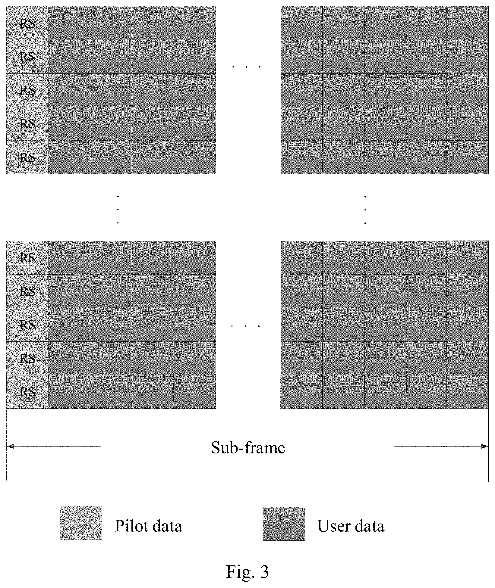
[0045] FIG. 3 is a schematic diagram of a pilot pattern including prepositive pilots according to an embodiment of the disclosure;
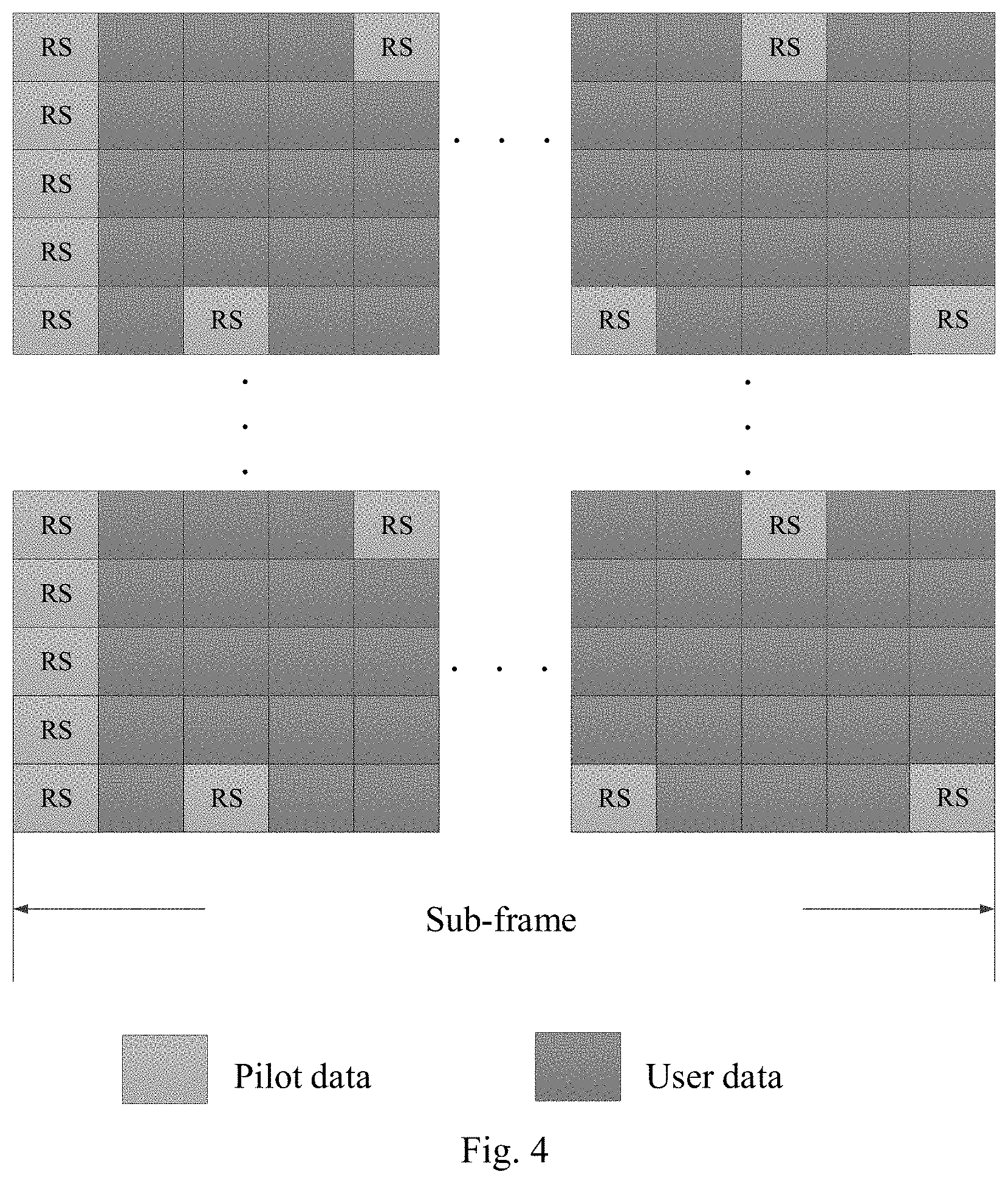
[0046] FIG. 4 is a schematic diagram of a pilot pattern including dynamic pilots according to an embodiment of the disclosure;
[0047] FIG. 5 is a schematic diagram of another pilot pattern including dynamic pilots according to an embodiment of the disclosure;
[0048] FIG. 6 is a schematic flow chart of a method for receiving a pilot according to an embodiment of the disclosure;
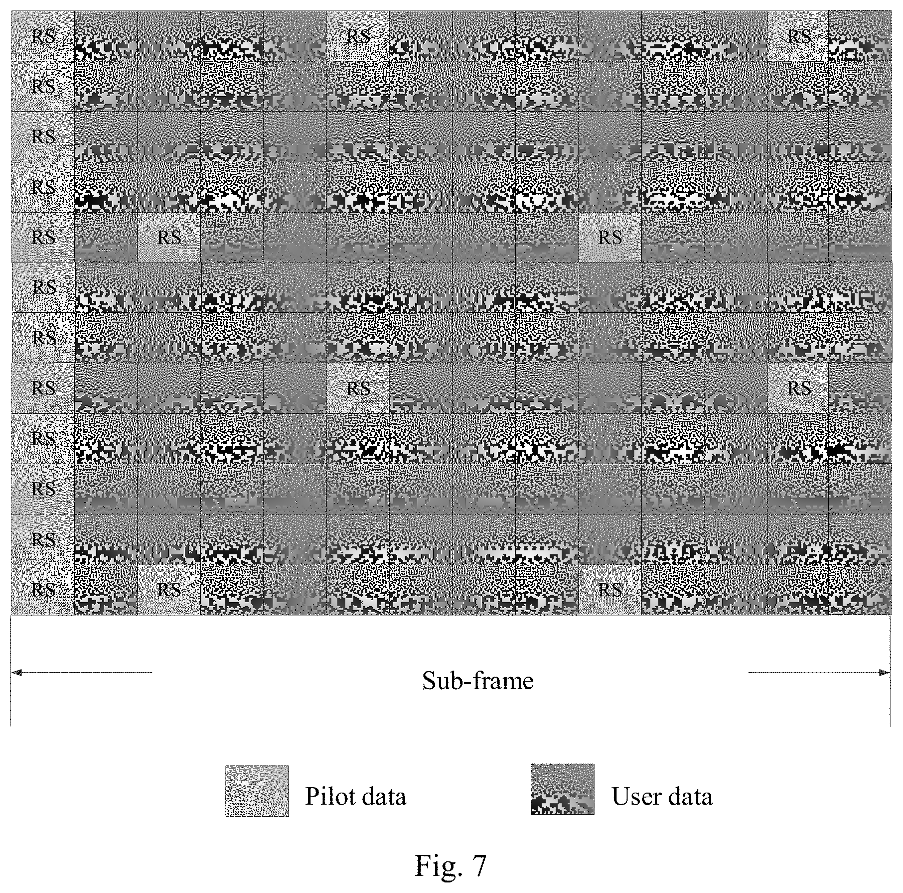
[0049] FIG. 7 is a schematic diagram of a pilot pattern according to a first embodiment of the disclosure;
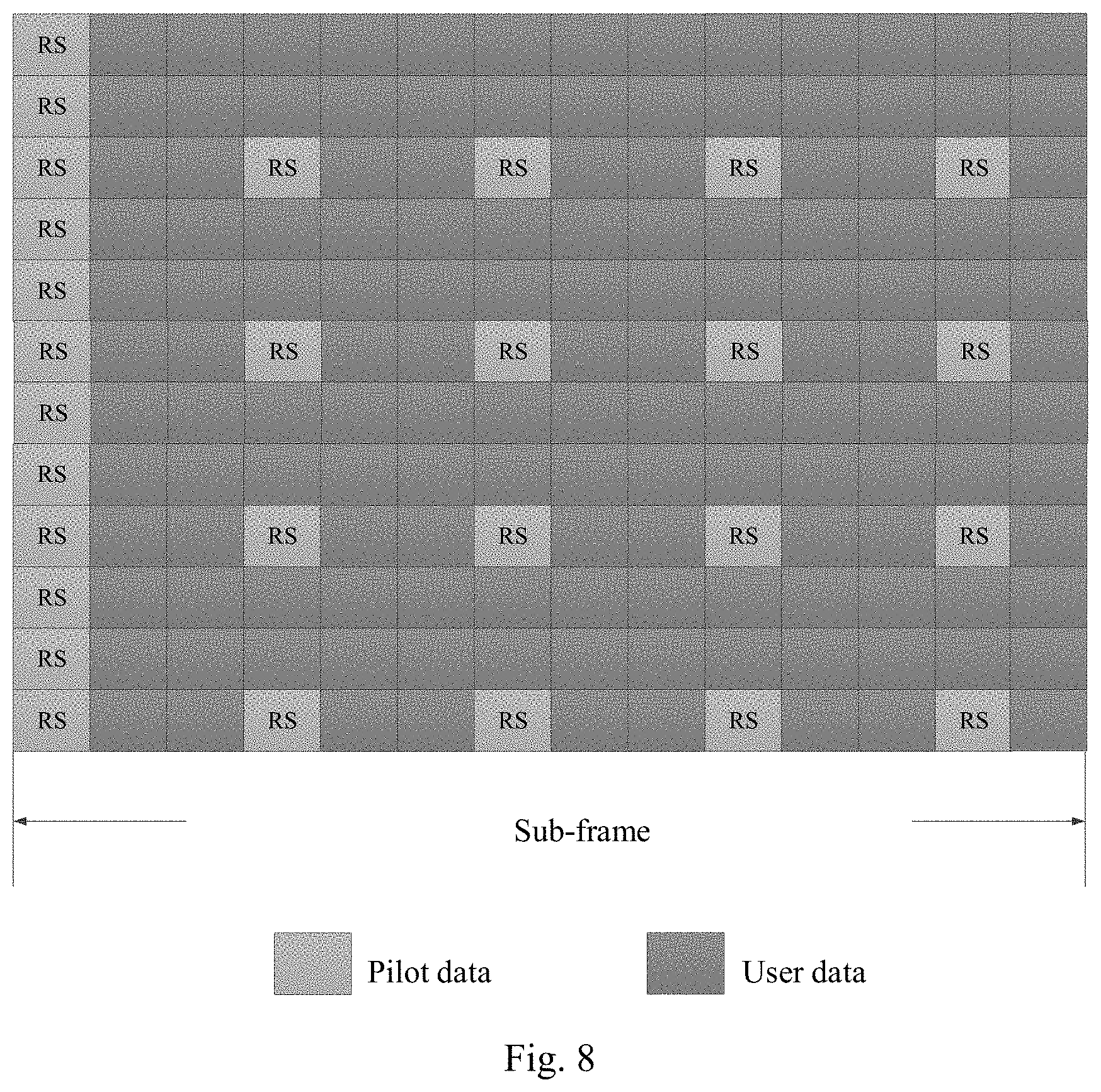
[0050] FIG. 8 is a schematic diagram of a pilot pattern according to a second embodiment of the disclosure;
[0051] FIG. 9 is a schematic structural diagram of an apparatus for sending a pilot according to an embodiment of the disclosure;
[0052] FIG. 10 is a schematic structural diagram of an apparatus for receiving a pilot according to an embodiment of the disclosure;
[0053] FIG. 11 is a schematic structural diagram of another apparatus for sending a pilot according to an embodiment of the disclosure; and
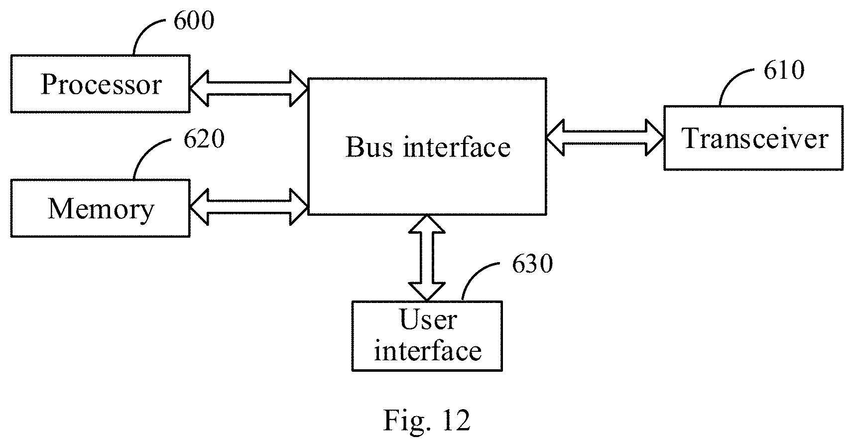
[0054] FIG. 12 is a schematic structural diagram of another apparatus for receiving a pilot according to an embodiment of the disclosure.
DETAILED DESCRIPTION OF THE EMBODIMENTS
[0055] The embodiments of the disclosure provide a method and apparatus for sending a pilot, and a method and apparatus for receiving a pilot so as to shorten a delay in receiving the pilot by a user equipment to thereby improve the efficiency of estimating a channel based upon the pilot.
[0056] As illustrated in FIG. 2, a method for sending a pilot according to an embodiment of the disclosure at the network side, e.g., the base station side, includes the following steps.
[0057] The step S101 is to determine a pilot pattern configured for a user equipment, where the pilot pattern includes time-frequency position information of pilots, and the time-frequency position information of the pilots includes position information of an initial time point of the pilots in sub-frames.
[0058] In the embodiment of the disclosure, fixed prepositive pilots can be arranged at a high density, that is, there is small spacing between adjacent pilot signals in the frequency domain, and for example, they are spaced by one or two REs, or pilots can be arranged in all the REs in the first symbols of the respective sub-frames. When there is a small length of a sub-frame (e.g. a sub-frame includes only five or seven symbols), a receiver (the user equipment) can obtain channel estimation throughout the sub-frame as early as possible using the prepositive pilots directly to thereby shorten a delay in reception, and improve the efficiency of channel estimation.
[0059] The prepositive pilots are arranged as pilots of REs corresponding to the first symbols of the sub-frames.
[0060] FIG. 3 illustrates a pilot pattern when pilots are arranged in all the REs in the first symbols of the respective sub-frames, for example.
[0061] The step S102 is to send the pilots to the user equipment according to the pilot pattern.
[0062] In the method above according to the embodiment of the disclosure, the user equipment can obtain the pilots throughout each sub-frame as early as possible using the prepositive pilots (the pilot at the initial time point in the sub-frame) directly instead of waiting until pilots at subsequent time point to the initial time point in the sub-frame are received, to thereby shorten a delay in receiving the pilots, and perform channel estimation using these pilots to thereby shorten a delay in channel estimation.
[0063] In one embodiment, the time-frequency position information of the pilots includes the position information of the initial time point of the pilots in the respective sub-frames.
[0064] In one embodiment, the initial time point in each sub-frame is particularly the first symbol of each sub-frame.
[0065] In one embodiment, the method further includes:
[0066] updating the pilot pattern of the user equipment so that the time-frequency position information of the pilots in the updated pilot pattern includes position information of the initial time point of the pilots in the sub-frames, and subsequent time points to the initial time point; and
[0067] sending the pilots to the user equipment in the updated pilot pattern.
[0068] Stated otherwise, after the prepositive pilots are configured, the user equipment can be further configured with pilots at adjustable densities and positions in the preamble pattern, and as opposed to the prepositive pilots, these pilots at the adjustable densities and positions in the preamble pattern can be referred to as dynamic pilots. The time and frequency densities thereof depend upon a coherence period of time and a coherence bandwidth of a user channel, and the base station can decide whether to issue the dynamic pilots, and determine a particular pilot pattern to be issued, according to a type of data (e.g., URLLC, eMBB, etc.), and a length of symbol occupied by the data.
[0069] In one embodiment, after the pilot pattern is updated for the user equipment, and before the pilots are sent to the user equipment in the updated pilot pattern, the method further includes:
[0070] sending control information to the user equipment to instruct the user equipment to receive the pilots.
[0071] In one embodiment, the control information includes indication information of the updated pilot pattern.
[0072] In one embodiment, updating the pilot pattern for the user equipment includes: updating the pilot pattern for the user equipment according to a coherence period of time and a coherence bandwidth of a user channel.
[0073] In a real application, the technical solution according to the embodiment of the disclosure can be applicable to different applications with different demands for channel estimation, and thus highly flexible.
[0074] For example, firstly, a fixed prepositive pilot signal in one symbol is arranged at an initial time point in each sub-frame as illustrated in FIG. 3. The prepositive pilot can be configured statically, that is, the positions of time and frequency resources occupied by the prepositive pilot can be determined when a cell is set up. However there is a high density (the highest density throughout a bandwidth as illustrated in FIG. 3) of the prepositive pilot in the frequency domain so that accurate and real-time channel estimation in the frequency domain can be guaranteed.
[0075] Furthermore, the base station issues control information in a control symbol region after the position of the symbol including the prepositive pilot, in a start sub-frame in each configuration periodicity of the pilot preamble. The control information includes a pilot pattern indication field indicating a pilot pattern for subsequent data symbols. Different indication fields represent different combinations of a pilot overhead, a pilot sequence, and pilot positions as depicted in Table 1. When a sub-frame includes a small number of symbols (e.g., a sub-frame includes only five or seven symbols), the base station configures no dynamic pilots, and the user equipment obtains channel estimation throughout the sub-frame by extending an estimation result of the prepositive pilot, that is, the user equipment duplicates the channel estimation result of the prepositive pilot into all the symbols throughout the sub-frame to thereby speed up reception of the pilots. For services with different reliability demands, the base station configures different pilot patterns according to different channel conditions (a coherence period of time, and a coherence bandwidth) of the user equipment: when there are a long channel coherence period of time, and a broad channel coherence bandwidth, a sparse pilot pattern is configured; and when there are a short channel coherence period of time, and a narrow channel coherence bandwidth, a dense pilot pattern is configured. The user equipment is provided with different estimation performance dependent upon different pilot overheads to thereby satisfy a reliability index. As illustrated in FIG. 4 and FIG. 5, there are a low density and a small overhead of dynamic pilots in FIG. 4, and they are applicable to a service scenario in which a channel changes slowly or high reliability is not required; and there is a high density of dynamic pilots in FIG. 5, and they are applicable to a service scenario in which a channel changes quickly or high reliability is required.
Table 1 is a pilot pattern indication table
TABLE-US-00001 [0076] Pilot pattern Pilot pattern to be Dynamic Pilot Pilot field value updated or not pilots sequence pattern 0 No -- -- -- 1 Yes None -- -- 2 Yes Available Sequence 1 Pattern 1 3 Yes Available Sequence 2 Pattern 2 4 Yes Available Sequence 3 Pattern 3 . . . . . . . . . . . .
[0077] It shall be noted that in the embodiment of the disclosure, a particular pilot sequence and a particular pilot pattern can be prescribed, and the control information can only include the number of the pilot pattern, and the number of the pilot pattern as depicted in Table 1 to thereby save an overhead of the control information; or the control information can only include the pilot pattern field value as depicted in Table, and the correspondence relationship table as depicted in Table 1 is stored in advance in the user equipment and the base station, so the UE can determine the currently updated pilot pattern, the pilot sequence for the dynamic pilots, etc., according to the pilot pattern field value.
[0078] The base station configures the sub-frame with the same pilot pattern as in the pilot patter indication field, and the user equipment parses the control information for the pilot pattern and the pilot sequence of the sub-frame, receives the data, and performs channel estimation.
[0079] In the next configuration periodicity of the pilot pattern (the periodicity can be configured statically, or can vary anytime, that is, can be configured dynamically), and the base station can decide whether to update the dynamic pilot pattern, according to the channel condition, and the type of user data to be scheduled, and indicate it to the user equipment in the control information.
[0080] It shall be noted that in the technical solution according to the embodiment of the disclosure, the configuration periodicity of the pilot pattern is flexibly variable, that is, the base station can set different configuration periodicities as needed, e.g., 80 ms, 160 ms, 320 ms, etc., where the shortest periodicity is a slot per sub-frame.
[0081] In correspondence to the method above for sending a pilot at the base station side, FIG. 6 illustrates a method for receiving a pilot at the user equipment side according to an embodiment of the disclosure, where the method includes the following steps:
[0082] the step S201 is to receive a pilot at an initial time point in a sub-frame; and
[0083] the step S202 is to determine channel estimation of the sub-frame using the pilot received at the initial time point in the sub-frame.
[0084] In one embodiment, the step S202 includes: performing channel estimation on the initial time point using the pilot received at the initial time point in the sub-frame, and determines channel estimation on the other time points in the sub-frame using a result of channel estimation on the initial time point, e.g., through duplication.
[0085] In one embodiment, the method further includes:
[0086] receiving control information to instruct the user equipment to receive pilots; and
[0087] receiving the pilots at the initial time point and its subsequent time points in the sub-frame according to the control information.
[0088] The control information is the information as depicted in Table 1, and when the base station updates a pilot pattern, it sends the control information to instruct the user equipment to receive the pilots in the new pilot pattern.
[0089] Two particular embodiments will be described below.
First Embodiment
[0090] Prepositive pilots are configured statically when a cell is set up, as illustrated in FIG. 3.
[0091] In a sub-frame n, a base station schedules a user equipment 1, allocates downlink time and frequency resources for the user equipment 1, configures dynamic pilots in a pilot pattern as illustrated in FIG. 7 according to a channel condition and a service type of the user equipment 1, and issues information about the dynamic pilots (including indication information of the positions of the pilots, a pilot sequence, etc.) to the user equipment side in downlink control information. In this embodiment, the user equipment accesses an eMBB service, and there is a slowly changing channel thereof, for example, so a sparse dynamic pilot pattern is applied thereto, that is, there is such a low density of the dynamic pilots that there are only two dynamic pilots after a prepositive pilot in a sub-frame, and the dynamic pilots may not be arranged in every sub-frame, but may be arranged at every other sub-frames.
[0092] Upon reception of downlink data, the user equipment firstly parses the control information, determines the pilot pattern in the current sub-frame according to the control information, and then performs channel estimation at the positions of the pilots in the pilot pattern, and performs interpolation with the prepositive pilot to obtain a channel estimation result throughout the sub-frame.
Second Embodiment
[0093] Prepositive pilots are configured statically when a cell is set up, as illustrated in FIG. 3.
[0094] In a sub-frame n, a base station schedules a user equipment 1, allocates downlink time and frequency resources for the user equipment 1, configures dynamic pilots as illustrated in FIG. 8 according to a channel condition and a service type of the user equipment 1, and issues information about the dynamic pilots to the user equipment side in downlink control information. In this embodiment, the user equipment accesses a URLLC service, and has no demand for high reliability, so a dense dynamic pilot pattern is applied thereto; and as illustrated in FIG. 8, there are four dynamic pilots after a prepositive pilot in a sub-frame, and four dynamic pilots are arranged in every other two sub-frames, so there is a higher density of the dynamic pilots than in the pilot pattern as illustrated in FIG. 7, and thus the user equipment can obtain more pilots, and perform channel estimation more accurately and reliably.
[0095] Upon reception of downlink data, the user equipment firstly parses the control information, determines the pilot pattern in the current sub-frame according to the control information, and then performs channel estimation at the positions of the dynamic pilots in the pilot pattern, and performs interpolation with the prepositive pilot to obtain a channel estimation result throughout the sub-frame.
[0096] Apparatuses according to the embodiments of the disclosure will be described below.
[0097] As illustrated in FIG. 9, an apparatus for sending a pilot at the base station side according to an embodiment of the disclosure includes:
[0098] a first device 11 is configured to determine a pilot pattern configured for a user equipment, where the pilot pattern includes time-frequency position information of pilots, and the time-frequency position information of the pilots includes position information of an initial time point of the pilots in sub-frames; and a second device 12 is configured to send the pilots to the user equipment according to the pilot pattern.
[0099] In one embodiment, the time-frequency position information of the pilots particularly includes the position information of the initial time point of the pilots in the respective sub-frames.
[0100] In one embodiment, the initial time point in each sub-frame is particularly the first symbol of each sub-frame.
[0101] In one embodiment, the first device is further configured: to update the pilot pattern of the user equipment so that the time-frequency position information of the pilots in the updated pilot pattern includes position information of the initial time point of the pilots in the sub-frames, and subsequent time points to the initial time point; and
[0102] the second device is further configured to send the pilots to the user equipment in the updated pilot pattern.
[0103] In one embodiment, the second device is further configured, after the first device updates the pilot pattern for the user equipment, and before the pilots are sent to the user equipment in the updated pilot pattern, to send control information to the user equipment to instruct the user equipment to receive the pilots.
[0104] In one embodiment, the control information includes indication information of the updated pilot pattern.
[0105] In one embodiment, the first device is configured to update the pilot pattern for the user equipment according to a coherence period of time and a coherence bandwidth of a user channel.
[0106] As illustrated in FIG. 10, an embodiment of the disclosure provides an apparatus for receiving a pilot at the user equipment side, where the apparatus includes:
[0107] a receiving device 21 is configured to receive a pilot at an initial time point in a sub-frame; and
[0108] a processing device 22 is configured to determine channel estimation of the sub-frame using the pilot.
[0109] In one embodiment, the receiving device is further configured:
[0110] to receive control information to instruct the user equipment to receive pilots; and
[0111] to receive the pilots at the initial time point and its subsequent time points in the sub-frame according to the control information.
[0112] As illustrated in FIG. 11, another apparatus for sending a pilot at the base station side according to an embodiment of the disclosure includes: a processor 500 configured to read and execute program in a memory 520:
[0113] to determine a pilot pattern configured for a user equipment, where the pilot pattern includes time-frequency position information of pilots, and the time-frequency position information of the pilots includes position information of an initial time point of the pilots in sub-frames; and
[0114] to send the pilots to the user equipment in the pilot pattern through a transceiver 510.
[0115] In one embodiment, the time-frequency position information of the pilots particularly includes the position information of the initial time point of the pilots in the respective sub-frames.
[0116] In one embodiment, the initial time point in each sub-frame is particularly the first symbol of each sub-frame.
[0117] In one embodiment, the processor 500 is further configured:
[0118] to update the pilot pattern of the user equipment so that the time-frequency position information of the pilots in the updated pilot pattern includes position information of the initial time point of the pilots in the sub-frames, and subsequent time points to the initial time point; and
[0119] to send the pilots to the user equipment in the updated pilot pattern through the transceiver 510.
[0120] In one embodiment, the processor 500 is further configured, after the first device updates the pilot pattern for the user equipment, and before the pilots are sent to the user equipment in the updated pilot pattern through the transceiver 510, to send control information to the user equipment through the transceiver 510 to instruct the user equipment to receive the pilots.
[0121] In one embodiment, the control information includes indication information of the updated pilot pattern.
[0122] In one embodiment the processor 500 is configured to update the pilot pattern for the user equipment according to a coherence period of time and a coherence bandwidth of a user channel.
[0123] The transceiver 510 is configured to transmit and receive data under the control of the processor 500.
[0124] Here in FIG. 11, the bus architecture can include any number of interconnecting buses and bridges to particularly link together various circuits including one or more processors represented by the processor 500, and one or more memories represented by the memory 520. The bus architecture can further link together various other circuits, e.g., a peripheral device, a manostat, a power management circuit, etc., all of which are well known in the art, so a further description thereof will be omitted in this context. The bus interface serves as an interface. The transceiver 510 can be a number of elements, e.g., a transmitter and a receiver, which are devices for communication with various other devices over a transmission medium. The processor 500 is responsible for managing the bus architecture and performing normal processes, and the memory 520 can store data for use by the processor 500 in performing the operations.
[0125] The processor 500 can be a Central Processing Unit (CPU), an Application-Specific Integrated Circuit (ASIC), a Field-Programmable Gate Array (FPGA), or a Complex Programmable Logic Device (CPLD).
[0126] As illustrated in FIG. 12, an embodiment of the disclosure provides another apparatus for receiving a pilot at the user equipment side, where the apparatus includes:
[0127] a processor 600 is configured to read and execute program in the memory 620:
[0128] to receive a pilot at an initial time point in a sub-frame through a transceiver 610; and
[0129] to determine channel estimation of the sub-frame using the pilot.
[0130] In one embodiment the processor 600 is further configured:
[0131] to receive control information to instruct the user equipment to receive pilots through the transceiver 610; and
[0132] to receive the pilots at the initial time point and its subsequent time points in the sub-frame according to the control information through the transceiver 610.
[0133] The transceiver 610 is configured to transmit and receive data under the control of the processor 600.
[0134] Here in FIG. 12, the bus architecture can include any number of interconnecting buses and bridges to particularly link together various circuits including one or more processors represented by the processor 600, and one or more memories represented by the memory 620. The bus architecture can further link together various other circuits, e.g., a peripheral device, a manostat, a power management circuit, etc., all of which are well known in the art, so a further description thereof will be omitted in this context. The bus interface serves as an interface. The transceiver 610 can be a number of elements, e.g., a transmitter and a receiver, which are devices for communication with various other devices over a transmission medium. For different user equipments, the user interface 630 can also be an interface via which devices are connected internally and externally as needed, and the connected devices include but will not be limited to a keypad, a monitor, a speaker, a microphone, a joystick, etc.
[0135] The processor 600 is responsible for managing the bus architecture and performing normal processes, and the memory 620 can store data for use by the processor 600 in performing the operations.
[0136] The processor 600 can be a Central Processing Unit (CPU), an Application-Specific Integrated Circuit (ASIC), a Field-Programmable Gate Array (FPGA), or a Complex Programmable Logic Device (CPLD).
[0137] In summary, in the embodiments of the disclosure, the prepositive pilots are arranged so that the receiver can obtain a channel estimation value earlier to thereby shorten a period of time for waiting, so as to shorten a delay in uni-direction in a URLLC scenario; and dynamic pilots can be sent dynamically as instructed in a control channel to thereby select different pilot patterns for different services so as to make a pilot overhead lie in a reasonable range.
[0138] Those skilled in the art shall appreciate that the embodiments of the disclosure can be embodied as a method, a system or a computer program product. Therefore the disclosure can be embodied in the form of an all-hardware embodiment, an all-software embodiment or an embodiment of software and hardware in combination. Furthermore the disclosure can be embodied in the form of a computer program product embodied in one or more computer useable storage mediums (including but not limited to a disk memory, a CD-ROM, an optical memory, etc.) in which computer useable program codes are contained.
[0139] The disclosure has been described in a flow chart and/or a block diagram of the method, the device (system) and the computer program product according to the embodiments of the disclosure. It shall be appreciated that respective flows and/or blocks in the flow chart and/or the block diagram and combinations of the flows and/or the blocks in the flow chart and/or the block diagram can be embodied in computer program instructions. These computer program instructions can be loaded onto a general-purpose computer, a specific-purpose computer, an embedded processor or a processor of another programmable data processing device to produce a machine so that the instructions executed on the computer or the processor of the other programmable data processing device create means for performing the functions specified in the flow(s) of the flow chart and/or the block(s) of the block diagram.
[0140] These computer program instructions can also be stored into a computer readable memory capable of directing the computer or the other programmable data processing device to operate in a specific manner so that the instructions stored in the computer readable memory create an article of manufacture including instruction means which perform the functions specified in the flow(s) of the flow chart and/or the block(s) of the block diagram.
[0141] These computer program instructions can also be loaded onto the computer or the other programmable data processing device so that a series of operational steps are performed on the computer or the other programmable data processing device to create a computer implemented process so that the instructions executed on the computer or the other programmable device provide steps for performing the functions specified in the flow(s) of the flow chart and/or the block(s) of the block diagram.
[0142] Although the preferred embodiments of the disclosure have been described, those skilled in the art benefiting from the underlying inventive concept can make additional modifications and variations to these embodiments. Therefore the appended claims are intended to be construed as encompassing the preferred embodiments and all the modifications and variations coming into the scope of the disclosure.
[0143] Evidently those skilled in the art can make various modifications and variations to the disclosure without departing from the spirit and scope of the disclosure. Thus the disclosure is also intended to encompass these modifications and variations thereto so long as the modifications and variations come into the scope of the claims appended to the disclosure and their equivalents.
* * * * *
D00000
D00001
D00002
D00003
D00004
D00005
D00006
D00007
D00008
XML
uspto.report is an independent third-party trademark research tool that is not affiliated, endorsed, or sponsored by the United States Patent and Trademark Office (USPTO) or any other governmental organization. The information provided by uspto.report is based on publicly available data at the time of writing and is intended for informational purposes only.
While we strive to provide accurate and up-to-date information, we do not guarantee the accuracy, completeness, reliability, or suitability of the information displayed on this site. The use of this site is at your own risk. Any reliance you place on such information is therefore strictly at your own risk.
All official trademark data, including owner information, should be verified by visiting the official USPTO website at www.uspto.gov. This site is not intended to replace professional legal advice and should not be used as a substitute for consulting with a legal professional who is knowledgeable about trademark law.