Image device with a compact homogenizer
Ishii; Fusao ; et al.
U.S. patent application number 16/798951 was filed with the patent office on 2020-06-18 for image device with a compact homogenizer. This patent application is currently assigned to Fusao Ishii. The applicant listed for this patent is Fusao NTT DOCOMO, INC. Ishii. Invention is credited to Yuji Aburakawa, Kazuoki Ichikawa, Fusao Ishii, Mikiko Nakanishi.
| Application Number | 20200192111 16/798951 |
| Document ID | / |
| Family ID | 71073583 |
| Filed Date | 2020-06-18 |


| United States Patent Application | 20200192111 |
| Kind Code | A1 |
| Ishii; Fusao ; et al. | June 18, 2020 |
Image device with a compact homogenizer
Abstract
A compact light source for a projection display is disclosed enabling eye-glass display using a Fresnel mirror reflecting light without a distance as conventional prism type reflector.
| Inventors: | Ishii; Fusao; (Pittsburgh, PA) ; Nakanishi; Mikiko; (Tokyo, JP) ; Ichikawa; Kazuoki; (Tokyo, JP) ; Aburakawa; Yuji; (Tokyo, JP) | ||||||||||
| Applicant: |
|
||||||||||
|---|---|---|---|---|---|---|---|---|---|---|---|
| Assignee: | Ishii; Fusao Pittsburgh PA NTT DOCOMO, INC. Tokyo |
||||||||||
| Family ID: | 71073583 | ||||||||||
| Appl. No.: | 16/798951 | ||||||||||
| Filed: | February 24, 2020 |
Related U.S. Patent Documents
| Application Number | Filing Date | Patent Number | ||
|---|---|---|---|---|
| 62809457 | Feb 22, 2019 | |||
| Current U.S. Class: | 1/1 |
| Current CPC Class: | G02B 2027/011 20130101; G02B 2027/0118 20130101; G02B 27/283 20130101; G02B 27/0172 20130101 |
| International Class: | G02B 27/28 20060101 G02B027/28; G02B 27/01 20060101 G02B027/01 |
Foreign Application Data
| Date | Code | Application Number |
|---|---|---|
| Jun 21, 2017 | US | PCT/US17/38523 |
Claims
1. An image device comprising 1) light source that irradiates light having wavelengths of a plurality of visible lights 2) a transparent waveguide having a Fresnel lens surface for receiving incident light from the edge of the waveguide and reflecting the Fresnel mirror surface 3) a Polarized Beam Splitter (PBS) where the light emitted from the wave guide is incident, 4) a display device wherein the reflected light is introduced into the PBS and an internal polarizing plate surface reflects the incident light toward the surface of the display device and changes the polarization of the incident light and reflects it towards the PBS.
2. The image device according to claim 1, wherein The display device is LCOS, LCD or Micromirror Device.
3. The image device according to claim 1, wherein The incoming light is directly reflected by Fresnel mirror or reflected by the flat surfaces of waveguide by total-internal-reflection.
4. The image device according to claim 1, The light source consists of three-color RGB LED.
5. The image device according to claim 1, The light source that irradiates continuous color spectrums lights.
6. An image device comprising 1) light source that irradiates light having wavelengths of a plurality of visible lights 2) a transparent waveguide having a Fresnel lens surface for receiving incident light from the edge of the waveguide and reflecting the Fresnel lens surface 3) a display device and 4) a set of prisms where the light is reflected toward a display device in an angle that is not normal direction of the surface of the display device.
7. The image device according to claim 6, wherein The display device is a Micromirror Device.
8. The image device according to claim 6, The incoming light is directly reflected by Fresnel mirror or reflected by the flat surfaces of waveguide by total-internal-reflection.
9. The image device according to claim 6, wherein, The light source consists of three-color RGB LED.
10. The image device according to claim 6, The light source that irradiates continuous color spectrums lights.
Description
CROSS REFERENCE TO RELATED APPLICATIONS
[0001] This application is a Non-Provisional application and claim the Priority Date of a previously filed Provisional Application 62/809,457 filed on Feb. 22, 2019, and this application is a Continuation in Part application of Ser. No. 16/252,267 filed on Jan. 19, 2019. Application Ser. No. 16/252,627 is a Continuation in Part (CIP) application of Patent Application PCT/US17/38523 filed on Jun. 21, 2017 which is a Non-Provisional filing of a Provisional Application 62/493,077 filed on Jun. 21, 2016.
TECHNICAL FIELD
[0002] The present invention relates to an image device having an illumination system of a wearable display system for projecting an image. More particularly, the present invention relates to an image device having a very compact illuminator suitable for a wearable display having a very small form factor.
BACKGROUND ART
[0003] Wearable displays provide the benefits of hands free operation as well as showing the images to the person who wears the display at a distance same as regular sight. However, the conventional near eye displays such as Head Mount Display, Head up Display and Eye Glass Type Display have not provided satisfied wearable display solutions to the viewers, because these conventional devices are often too heavy, too large, and too dark. Therefore, there are urgent needs for providing wearable display devices that are light, small, bright, having high resolution with see-through viewing optical path.
[0004] It is further desirable that the new wearable devices can be produced at a reasonable lower cost and can display large image. It is further desirable that a person can wear such devices can in a stealthy manner without being ostensibly detected by others that the person is wearing such a wearable device. Display systems implemented with LED and Laser light sources usually have a technical problem with uneven distribution of light intensity and a homogenizer is typically required for the display systems to provide uniform brightness of image. Three separate color light sources require to combine into a single light beam before projecting onto a display device. Enabling a compact eye-glass type display requires a very small system having both homogenizer and combiner. Several systems are proposed in the past.
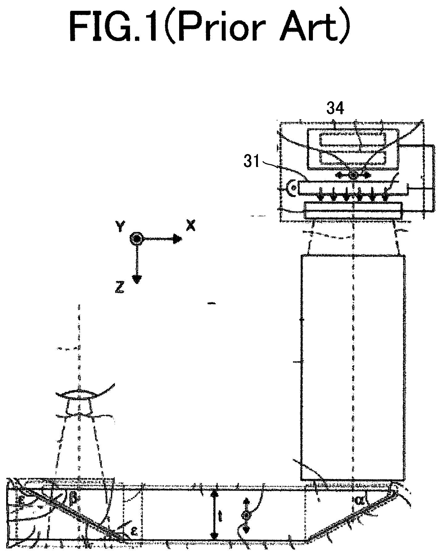
[0005] As shown in FIG. 1, Takeda et al. disclosed in U.S. Pat. No. 8,711,487 an eye glass type display system that implements see-through capability with a wave guide and a half-mirror. This system incorporates a transmissive LCD as a display and the illumination system is a backlight light-guide that diffuses the light from the light source. This system is suitable for transmissive LCD, but not necessarily suitable for other display devices such as LCOS and DMD.
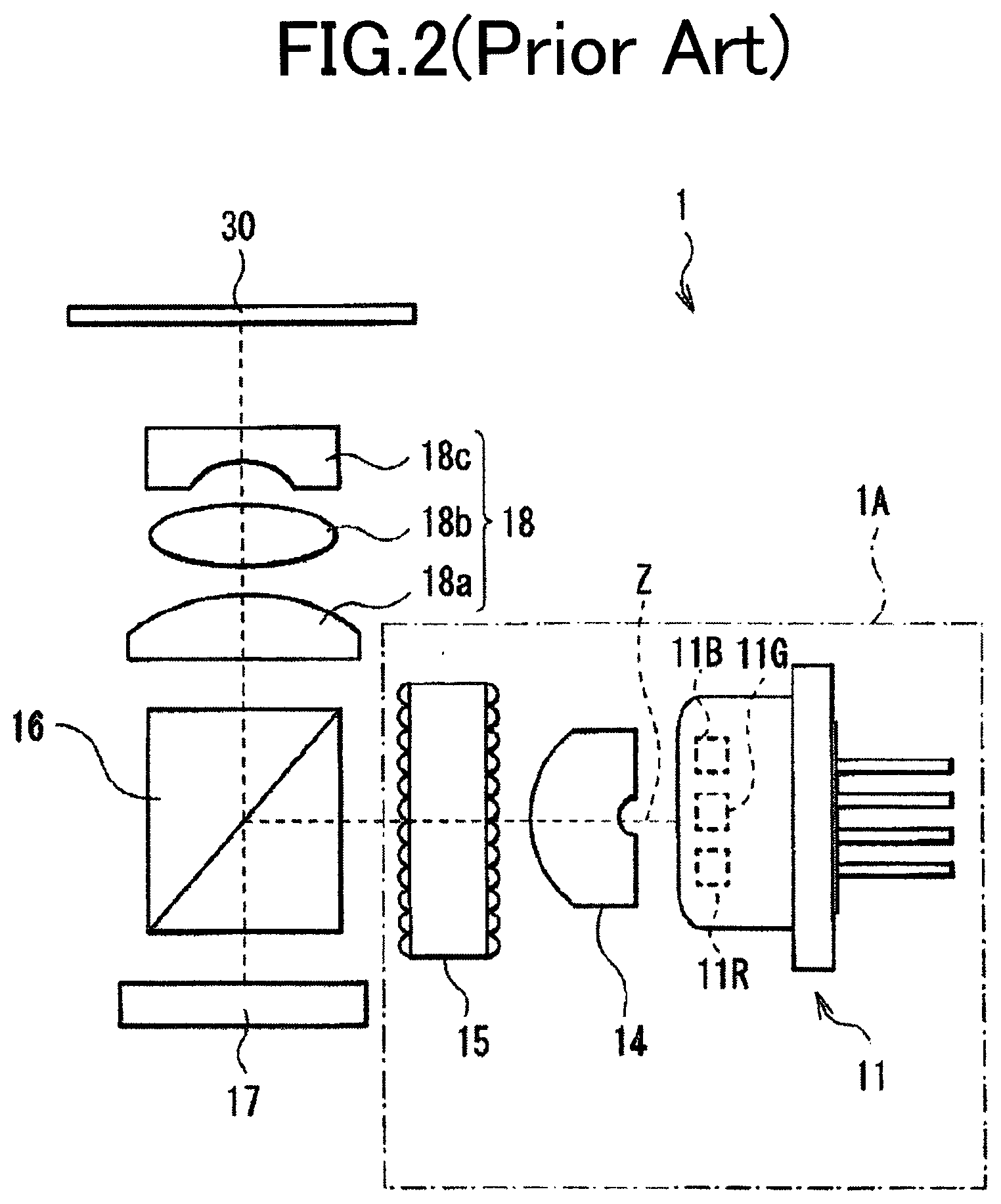
[0006] As shown in FIG. 2 and FIG. 2A, Takahashi et al. disclosed in US Patent Application Publication US2013/0021581 an illuminator and a display for miniaturization. The system comprises multi-color light sources such as LED and Laser (11) with micro-lenses (116) to collimate, dichroic mirrors (117) to combine light beams as shown in FIG. 2 A and a polarized beam splitter (PBS, 16) arranged in perpendicular direction from LCOS (17). If this is used for an eye-glass display and embedded in a temple of glasses, this illuminator will stick out of the temple of glasses. In FIG. 2, Light beams from LEDs (11B, 11G, 11R) are condensed by a condenser lens (14) and a micro-lens array (15) and lead to a PBS (16, Polarize Beam Splitter) then focused by a lens set (18a, 18b, 18c) through a cover glass (30). In FIG. 2A, Light sources (11R, 11G, 11B) emit light beams (Lr, Lg, Lb) and the beams are collimated by collimation lenses (116a, 116b, 116c, 116) held by frames (116s) and the collimated beams are reflected by a mirror (117c) and dichroic mirrors (117a, 117b) through a filter (118).
[0007] As shown in FIG. 3, Katsumata et al. disclosed in JP2013-195603 a Planar Lightwave Circuit (PLC). A beam from a laser diode is lead into a light-wave guide and the light energy in a light-wave can be transferred to an adjacent light-wave guide in a certain condition. This method is suitable for a combiner of laser light sources and has a great potential, although it requires further study prior to high volume. FIG. 3 is disclosed by Katsumata et al. Disclosed in JP 2013-195603, a Planar Lightwave Circuit (10, 220, PLC). A beam from a laser diode is lead into a light-wave guide and the light energy in a light-wave This is another way to combine multiple light beams into one. Laser beams are inputted at openings (101a, 102a, 103a) of optical fibers (101, 102, 103). Light beams are integrated at integrators (110, 120, 130 and a phase controller (140).
SUMMARY OF THE INVENTION
[0008] This image type is an ultra-compact flat homogenizer and diffuser. This type is based on Fresnel lens wave guide, display device and a cubic PBS. This type of compact display is suitable for a wearable display.
BRIEF DESCRIPTION OF THE DRAWINGS
[0009] FIG. 1 is a structure of see-through display shown by Takeda et al. Disclosed in U.S. Pat. No. 8,711,487. As an illuminator for a LCD display panel, a backlight module was used.
[0010] FIG. 2 and FIG. 2A are shown by Takahashi et al. In US Patent Application Publication US 2013/0021581, referred to as an expander lens and a micro-lens are used to provide light to a PBS.
[0011] FIG. 3 is disclosed by Katsumata et al. Disclosed in JP 2013-195603, a Planar Lightwave Circuit (PLC). A beam from a laser diode is lead into a light-wave guide and the light energy in a light-wave This is another way to combine multiple light beams into one.
[0012] FIG. 4 is a cross-sectional diagram of an image device 1001 according to a preferred embodiment.
[0013] FIG. 5 shows a detailed cross-sectional view of the transparent waveguide 1031 according to a preferred embodiment.
[0014] FIG. 6 shows an example of eye-glass display using this invention.
[0015] FIG. 7 shows another example of this invention. The light emitted from the light source 1001 propagates inside the homogenizer 1005 and is reflected by total-internal-reflection (TIR) by both top and bottom surfaces and reflected by the surfaces of Fresnel mirror (1008) to outside.
[0016] FIG. 8 shows another example of this invention. The light emitted from the light source (1001) propagates inside the homogenizer (1005) and reflected by TIR. The other edge-surface (1010) reflects back the internal light to increase the output with the surfaces in two direction of Fresnel mirror.
[0017] FIG. 9 shows another example of this invention. The light emitted by the light source (1001) is reflected by the homogenizer (1003) toward a set of prism (1005 and 1006), often referred as TIR prism. The reflected by TIR prism is lead to a display device (1008) and reflected through the TIR prism.
DETAIL DESCRIPTIONS OF PREFERRED EMBODIMENTS
[0018] FIG. 4 is a cross-sectional diagram of an image device 1001 according to a preferred embodiment 1. The image device 1001 is incorporated in a head mounted display or an eyeglass type display to form an image as that shown in FIG. 6 below. FIG. 5 shows a detailed cross section of the transparent waveguide 1031 according to a preferred embodiment.
[0019] The image device 1001 is composed of a light source 1011, a Lens 1021, a transparent waveguide 1031, a Polarized Beam Splitter (PBS) 1041 and display device 1051.
[0020] The light source 1011 is also the light source with light source 1011 consist of three-color RGB LED. The visible lights are RGB light. Also, the light source 1011 may be irradiates continuous color spectrums lights.
[0021] The waveguide 1031 has a function as a homogenizer and diffuser. In the waveguide 1031, the visible light irradiated by the light source 1011 is incident from the edge 1032 of the wave guide through the lens 1021. The waveguide 1031 has Fresnel lens surfaces 1033. The visible light incident from the edge 1071c is reflected by Fresnel lens surfaces 1033 (Saw shape). Light 1071a a reflects to Light 1072a a. Light 1071 b is reflected to Light 1072 b. Light 1071 c reflects to Light 1072 c. The light axes centers of the lights 1071 a, 1071 b, and 1071 c are not parallel to each other. However, due to the reflection at the Fresnel lens surfaces 1033, the light axes centers of the lights 1072a, 1072b, and 1072c are parallel to each other. Light 1072a, 1072b, 1072c exit waveguide surface 1034.
[0022] The PBS 1041 is a cube-like structure having an internal polarizing plate surface 1042. Light 1072a, 1072b, 1072c are reflected by the internal polarizing plate surface 1042 and reach the display device 1051 as lights 1073a, 1073b, 1073c.
[0023] The display device 1051 is an image generating device composed of liquid crystal on silicon (LCOS). The display device 1051 is installed on the circuit board 1061. Light 1073a, 1073b, 1073c are irradiated to the LCOS. The LCOS is controlled to form an image on the circuit board 1061. Then, it reflects the light 1074a, 1074b, 1075c corresponding to the image. Light 1074a, 1074b, 1075c is incident on the PBS 1041, passes through the internal polarizing plate surface 1042, and exits the PBS 1041. The lights 1074a, 1074b, and 1075c form images on human eyes through other optical systems constituting the head mounted display. The display device 1051 may be a liquid crystal display (LCD) or a micromirror device.
[0024] FIG. 6 shows an example of this invention, A light source (1084) emits light through a lens (1083) to this invention's homogenizer (1077) which outputs light in uniform distribution toward the PBS (1071). The PBS reflects the incoming light to a display device (1074) and the display device reflects light through the PBS to a lens set (1085) to project an image to a waveguide (1086) and the light propagates inside the waveguide with total-internal-reflection (TIR) and reflected to a viewer's eye (1089).
[0025] With the above configuration, it is possible to irradiate parallel and homogeneous light to the PBS by a very flat waveguide working as a flat homogenizer. Therefore, it is possible to provide a wearable display device that is bright, small, bright, and high resolution using a transparent optical path.
[0026] FIG. 5 shows an example of embodiment of homogenizer using Fresnel mirror at one side of homogenizer (1031), wherein the light beams from a light source is directly reflected to the next target without TIR.
[0027] FIG. 7 shows an example of embodiment of this invention of homogenizer wherein the incoming light is reflected by TIR internally and reflected to outside.
[0028] FIG. 8 shows another example of embodiment wherein the incoming light is reflected by top and bottom surfaces and also reflected by side edge surfaces with double direction Fresnel mirror.
[0029] FIG. 9 is an example of this invention wherein the outputted light from a homogenizer is lead to a set of prisms (TIR prism) and reflected by a display device toward a set of projection lens.
* * * * *
D00000
D00001
D00002
D00003
D00004
D00005
D00006
D00007
D00008
D00009
XML
uspto.report is an independent third-party trademark research tool that is not affiliated, endorsed, or sponsored by the United States Patent and Trademark Office (USPTO) or any other governmental organization. The information provided by uspto.report is based on publicly available data at the time of writing and is intended for informational purposes only.
While we strive to provide accurate and up-to-date information, we do not guarantee the accuracy, completeness, reliability, or suitability of the information displayed on this site. The use of this site is at your own risk. Any reliance you place on such information is therefore strictly at your own risk.
All official trademark data, including owner information, should be verified by visiting the official USPTO website at www.uspto.gov. This site is not intended to replace professional legal advice and should not be used as a substitute for consulting with a legal professional who is knowledgeable about trademark law.