Head Up Display (hud) Using A Light Pipe
Yu; Ming ; et al.
U.S. patent application number 16/354069 was filed with the patent office on 2020-06-18 for head up display (hud) using a light pipe. The applicant listed for this patent is Rockwell Collins, Inc.. Invention is credited to Robert D. Brown, Eric P. Stratton, Ming Yu.
| Application Number | 20200192088 16/354069 |
| Document ID | / |
| Family ID | 71071504 |
| Filed Date | 2020-06-18 |


| United States Patent Application | 20200192088 |
| Kind Code | A1 |
| Yu; Ming ; et al. | June 18, 2020 |
HEAD UP DISPLAY (HUD) USING A LIGHT PIPE
Abstract
A head up display can be used in compact environments. The head up display includes a combiner system including at least one light pipe and a waveguide. The at least one light pipe includes a turning grating or mirror array for providing light into the waveguide from the light pipe. An additional light pipe can also be provided. The combiner system can be head worn or stand-alone and can provide dual axis pupil expansion.
| Inventors: | Yu; Ming; (Beaverton, OR) ; Stratton; Eric P.; (Portland, OR) ; Brown; Robert D.; (Lake Oswego, OR) | ||||||||||
| Applicant: |
|
||||||||||
|---|---|---|---|---|---|---|---|---|---|---|---|
| Family ID: | 71071504 | ||||||||||
| Appl. No.: | 16/354069 | ||||||||||
| Filed: | March 14, 2019 |
Related U.S. Patent Documents
| Application Number | Filing Date | Patent Number | ||
|---|---|---|---|---|
| 15136841 | Apr 22, 2016 | 10247943 | ||
| 16354069 | ||||
| 14715332 | May 18, 2015 | 10088675 | ||
| 15136841 | ||||
| 14814020 | Jul 30, 2015 | 9523852 | ||
| 14715332 | ||||
| 16020125 | Jun 27, 2018 | |||
| 14814020 | ||||
| 14715332 | May 18, 2015 | 10088675 | ||
| 16020125 | ||||
| Current U.S. Class: | 1/1 |
| Current CPC Class: | G02B 27/283 20130101; G02B 27/0176 20130101; G02B 2027/0174 20130101; G02B 2027/0154 20130101; G02B 27/0081 20130101; G02B 27/0172 20130101; G02B 6/0028 20130101; G02B 2027/0123 20130101 |
| International Class: | G02B 27/00 20060101 G02B027/00; G02B 27/01 20060101 G02B027/01 |
Claims
1. A head up display, comprising: a first light pipe comprising a first elongated face, a second elongated face, a third elongated face, and a fourth elongated face, the first elongated face extending in a first direction and coplanar with the second elongated face, the first light pipe comprising a first input grating configured to couple light into the first light pipe, the first light pipe comprising at least one first turning grating or first mirror array configured to expand a pupil in the first direction; and a waveguide combiner configured to expand the pupil in a second direction perpendicular to the first direction and comprising an output grating, wherein the light enters the first light pipe in a third direction and the light leaves the waveguide combiner in the third direction and the third direction is perpendicular to the first direction and the second direction.
2. The head up display of claim 1, wherein the light enters the first light pipe at the first elongated face and the first input grating is on a second elongated face opposite the first elongated face.
3. The head up display of claim 2, wherein the first elongated face comprises the at least one first turning grating.
4. The head up display of claim 1, wherein the first light pipe comprises at least one first mirror array.
5. The head up display of claim 1, wherein the second elongated face comprises a second turning grating or a second mirror array.
6. The head up display of claim 1, wherein the output grating is rectangular.
7. The head up display of claim 6, wherein the first light pipe is attached to the waveguide combiner at a top surface of the waveguide combiner, the top surface matching the third elongated face.
8. The head up display of claim 1, wherein the first light pipe comprises two high efficiency mirror gratings.
9. A method of providing information to a user, the method comprising: directing light from an image source in a first direction perpendicular to the first direction with a first grating in a first light pipe; propagating the light down the first light pipe and a second light pipe attached the first light pipe and expanding a pupil in the first direction; and providing the light from the second light pipe to a waveguide combiner using a turning grating, wherein the waveguide combiner is configured to expand the pupil in a second direction perpendicular to the first direction and comprises an output grating, wherein the light entering the first grating and light exiting the output grating travels in the same direction.
10. The method of claim 9, wherein the turning grating of the second light pipe is disposed on a first elongated surface opposite a second elongated surface of the waveguide combiner, the second elongated surface comprising the first grating.
11. The method of claim 9, further comprising: the first and second light pipes are attached together.
12. The method of claim 9, wherein the second light pipe is attached to the waveguide combiner at a top surface of the waveguide combiner, the top surface matching a third elongated surface of the second light pipe.
13. The method of claim 9, wherein the second light pipe disposed between the first light pipe and the waveguide combiner.
14. A head up display system, comprising: at least one light pipe comprising an input grating and a turning grating, wherein the light travels down the light pipe as a spiral ray, wherein the light pipe is configured to expand a pupil in a first direction; and a waveguide combiner, the at least one light pipe propagates the light into the waveguide combiner from the light pipe via the turning grating, the waveguide combiner comprises an output grating and the waveguide combiner configured to expand the pupil in a second direction perpendicular to the first direction.
15. The head up display system of claim 14, further comprising an additional light pipe.
16. The head up display system of claim 15, wherein the additional light pipe is attached to the light pipe and the waveguide combiner.
17. The head up display system of claim 14, further comprising an input structure attached to the light pipe, the input structure comprising an interface grating.
18. The head up display system of claim 14, wherein the output grating is in an XY plane and the input grating is in the XY plane, and wherein the light travels down the light pipe in an X direction in an XYZ coordinate system.
19. The head up display system of claim 14, wherein the input grating is in an XZ plane and the turning grating is in the XZ plane, and wherein the light travels down the light pipe in an X direction in an XYZ coordinate system.
20. The head up display system of claim 14, wherein the turning grating and the output grating are on a same side.
Description
CROSS REFERENCE TO RELATED APPLICATIONS
[0001] The present application is a continuation-in-part of U.S. patent application Ser. No. 15/136,841 (Attorney Docket No. 15FD471C (047141-1108)) filed on Apr. 22, 2016, entitled "A Head Up Display (HUD) Using a Light Pipe" incorporated herein by reference in its entirety and assigned to the assignee of the present application," which is a continuation-in-part of U.S. patent application Ser. No. 14/715,332 (now U.S. Pat. No. 10,088,675) (Attorney Docket No. 15FD011 (047141-1047) filed on May 18, 2015, entitled "A Turning Light Pipe for A Pupil Expansion system and Method" incorporated herein by reference in its entirety and assigned to the assignee of the present application and a continuation-in-part of U.S. patent application Ser. No. 14/814,020 (now U.S. Pat. No. 9,523,852) (Attorney Docket No. 15FD471 (047141-1085)) filed on Jul. 30, 2015, entitled "Micro Collimator System and Method for a Head Up Display (HUD)" incorporated herein by reference in its entirety and assigned to the assignee of the present application. The present application is also a continuation-in-part of U.S. patent application Ser. No. 16/020,125 (Attorney Docket No. 15FD011C 047141-1373) filed Jun. 27, 2018, entitled "Turning Light Pipe For A Pupil Expansion System and Method", incorporated herein by reference in its entirety and assigned to the assignee of the present application which is a continuation of U.S. patent application Ser. No. 14/715,332 (now U.S. Pat. No. 10,088,675) (Attorney Docket No. 15FD011 (047141-1047), filed May 18, 2015, entitled "Turning Light Pipe For a Pupil expansion System and Method, incorporated herein by reference in its entirety and assigned to the assignee of the present application which is related to U.S. patent application Ser. No. 13/432,662 (now U.S. Pat. No. 9,366,864 (Attorney Docket No. 11FD225 (047141-0843)) filed on Mar. 28, 2012 entitled "System For And Method of Catadioptric Collimation In A Compact Head Up Display (HUD)," incorporated herein by reference in its entirety and assigned to the assignee of the present application, which is a continuation-in-part application of U.S. patent application Ser. No. 13/250,621 (now U.S. Pat. No. 8,634,139) (Attorney Docket No. 11FD241 (047141-0808)) filed on Sep. 30, 2011 entitled "System For And Method of Catadioptric Collimation In A Compact Head Up Display (HUD)," incorporated herein by reference in its entirety and assigned to the assignee of the present application; "U.S. patent application Ser. No. 13/250940, (Attorney Docket No. 11FD299 (047141-0819)), entitled, "Head Up Display (HUD) Utilizing Diffractive Gratings Having Optimized Efficiency," filed on Sep. 30, 2011, incorporated herein by reference in its entirety, and assigned to the assignee of the present application, now abandoned; U.S. patent application Ser. No. 13/250,0858 (now U.S. Pat. No. 9,715,067) (Attorney Docket No. 11FD126 (047141-0807)), entitled, "Ultra-Compact HUD Utilizing Waveguide Pupil Expander With Surface Relief Gratings In High Refractive Index Materials," filed on Sep. 30, 2011, incorporated herein by reference in its entirety, and assigned to the assignee of the present application; U.S. patent application Ser. No. 13/251,087 (now U.S. Pat. No. 8,903,207), (Attorney Docket No. 11FD0307 (047141-0820)), entitled, "System for and Method of Extending Vertical Field of View in Head Up Display Utilizing a Waveguide Combiner," filed on Sep. 30, 2011, incorporated herein by reference in its entirety, and assigned to the assignee of the present application; U.S. patent application Ser. No. 13/250,970 (now U.S. Pat. No. 8,937,772), (Attorney Docket No. 11FD096 (047141-0785)), entitled, "System For and Method of Stowing HUD Combiners," filed on Sep. 30, 2011 and assigned to the assignee of the present application, incorporated herein by reference in its entirety; and U.S. patent application Ser. No. 13/250,994 (now U.S. Pat. No. 8,749,890), (Attorney Docket No. 11FD122 (047141-0786)), entitled, "Compact Head Up Display (HUD) for Cockpits with Constrained Space Envelopes," filed on Sep. 30, 2011, incorporated herein by reference herein in its entirety and assigned to the assignee of the present application.
BACKGROUND
[0002] Embodiments of the inventive concepts disclosed herein relate to substrate guided displays including but not limited to head up displays (HUDs), such as, fixed HUDs and worn displays (e.g., head worn displays, helmet mounted displays, virtual glasses, etc.).
[0003] HUDs provide significant safety and operational benefits including precise energy management and conformal flight paths. These safety and operational benefits are enjoyed by operators of air transport aircraft, military aircraft, regional aircraft and high end business jets where HUDs are generally employed. These safety and operational benefits are also desirable in smaller aircraft.
[0004] Conventional HUDs are generally large, expensive and difficult to fit into smaller aircraft, such as, business and regional jets as well as general aviation airplanes. Often, conventional HUDs rely on large optical components to form adequate field of view and viewing eye box. The large optical components are often associated with collimating or non-collimating projectors and include lens, prisms, mirrors, etc. The volume of the packages including the optical components of the HUD is too large to fit within the constrained space in the cockpit of smaller aircraft. Further, conventional HUDs rely upon optical components which are generally too expensive for the cost requirements of smaller aircraft and worn displays.
[0005] Substrate guided HUDs have been proposed which use waveguide technology with diffraction gratings to preserve eye box size while reducing size of the HUD. U.S. Pat. No. 4,309,070 issued St. Leger Searle and U.S. Pat. No. 4,711,512 issued to Upatnieks disclose substrate waveguide HUDs. U.S. Pat. No. 8,634,139 discloses a catadioptric collimator for HUDs. The U.S. patent applications listed in the Cross Reference to Related Applications above disclose compact head up displays (HUDS) and near eye displays using multiple gratings, multiple waveguides, and/or multiple waveguide layers for pupil expansion.
[0006] It is desirous to make the projector for waveguide HUDs in a compact arrangement. Aligning optical components in small projector implementations can be difficult especially as sizes are minimized. Folded paths used in conventional projectors can require optical components that add to the package size for the projector. Projectors also often require a corrector lens which can be expensive and add to size of the collimator.
[0007] Pupil expansion using multiple layers or multiple waveguides with input and output diffraction gratings adds to the complexity of the waveguide display. For example, pupil expansion using multiple layers, multiple waveguides, and/or multiple gratings can add to the size, weight and cost of the display and can reduce the brightness and contrast of the display. Further, expanding the pupil from a small round collimating lens in two directions using two or more waveguides or using three or more gratings to produce a final expanded pupil can be glossy due to air gaps and the number of gratings. The air gaps can induce geometric coupling losses. Further, expanding the pupil from a small round collimating lens in two directions using two or more waveguides or using three or more gratings to produce a final expanded pupil can add haze to the final image.
SUMMARY
[0008] In one aspect, embodiments of the inventive concepts disclosed herein relate to a head up display. The head up display is for use with an image source. The head up display includes a collimating mirror and a polarizing beam splitter. Light from the image source enters the beam splitter and is reflected toward the collimating mirror. The light striking the collimating mirror is reflected through the polarizing beam splitter toward a combiner.
[0009] In a further aspect, embodiments of the inventive concepts disclosed herein relate to a head up display. The head up display includes a field lens disposed to receive light directly from the image source. The field lens has a diffractive surface for increasing power of the field lens and providing color correction. The head up display also includes a polarizing beam splitter having a first face, a second face, and a third face. The field lens is disposed to provide light to the first face, and the polarizing beam splitter is configured to reflect light of a first polarization toward the second face. The light from the image source has the first polarization. The head up display system also includes a retarder disposed to receive light from the second face, and a curved reflector disposed to receive light from the retarder and provide the light from the retarder to the second face. The light entering the second face has a second polarization state and the polarizing beam splitter is configured so that the light entering the second face travels from the second face to the third face.
[0010] In a further aspect, embodiments of the inventive concepts disclosed herein relate to a head up display. The head up display includes an image source, an illuminator, a field lens arranged to receive light directly from the image source, a polarizing beam splitter having a first face, a second face, a third face, and a fourth face, a retarder disposed to receive the light provided through the second face, and a curved reflector. The field lens has a diffractive surface for providing color correction and having a higher order of aberration control, and the illuminator is arranged to illuminate the image source through the polarizing beam splitter through the fourth face and the first face. The light from the illuminator entering the fourth face has a second polarization state, and the field lens is disposed to provide the light from the image source to the first face. The polarizing beam splitter is configured to reflect light of a first polarization state through the second face, wherein the light from the image source has the first polarization state. The curved reflector is disposed to receive light from the retarder and to provide the light from the retarder back through the retarder to the second face. The light entering the second face has a second polarization state, and the polarizing beam splitter is configured so that the light entering the second face travels from the second face to the third face. The light at the third face is provided for display on the head up display.
[0011] In a further aspect, embodiments of the inventive concepts disclosed herein relate to a method of providing information to a pilot. The method includes providing light from a light source to an image source through a polarizing beam splitter, providing light from the image source to the polarizing beam splitter and reflecting the light from the image source within the polarizing beam splitter to a curved reflective surface. The method also includes providing light from the curved reflective surface through the polarizing beam splitter to a corrector lens, and providing the light from the corrector lens as collimated light to a wave guide combiner.
[0012] In still further aspect, the inventive concepts disclosed herein related to a catadioptric optical system for a head up display. The catadioptric optical system includes a polarizing beam splitter, a light source disposed on a first side of the polarizing beam splitter, an image source disposed on a second side of the polarizing beam splitter opposite the first side of the polarizing beam splitter, and a first lens disposed between the image source and the second side. The catadioptric optical system also includes a reflective surface disposed on a third side of the polarizing beam splitter, and a second element disposed on a fourth side of the polarizing beam splitter.
[0013] In one aspect, embodiments of the inventive concepts disclosed herein relate to a head up display. The head up display includes a first light pipe and a waveguide combiner. The first light pipe is configured to expand a pupil in a first direction and includes at least one turning grating or mirror array. The waveguide combiner is configured to expand the pupil in a second direction perpendicular to the first direction.
[0014] In a further aspect, embodiments of the inventive concepts disclosed herein related to a method. The method provides information to a pilot. The method includes providing light from an image source, providing the light from the image source to a first light pipe and expanding the pupil in the first direction in the light pipe, and providing light from the light pipe to a waveguide combiner.
[0015] In still further aspect, embodiments of the inventive concepts disclosed herein related to a head up display. The head up display includes at least one light pipe and a waveguide. The at least one light pipe includes a turning grating or mirror array for providing light into the waveguide from the light pipe.
BRIEF DESCRIPTION OF THE DRAWINGS
[0016] Exemplary embodiments of the inventive concepts disclosed herein are hereafter described with reference to the accompanying drawings, wherein like numerals denote like elements; and:
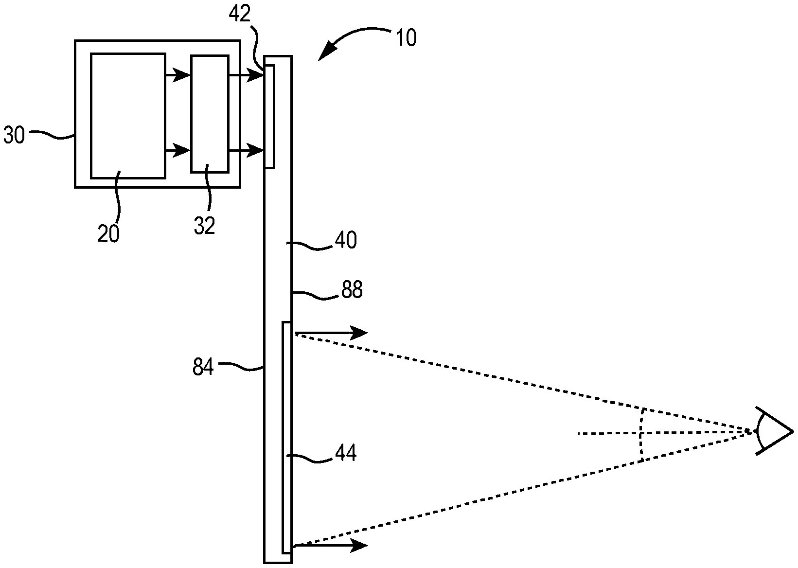
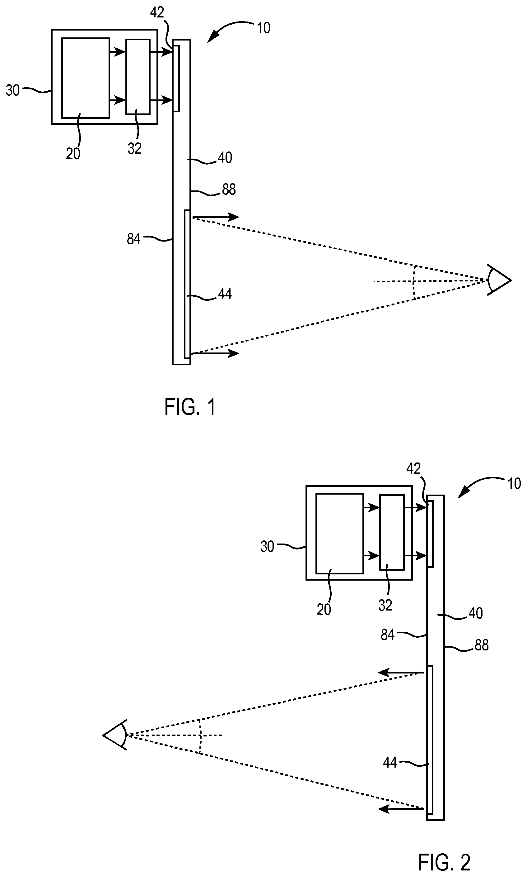
[0017] FIG. 1 is a general block diagram of a head up display (HUD) display system in accordance with some exemplary embodiments of the inventive concepts disclosed herein;
[0018] FIG. 2 is a general block diagram of a HUD system in accordance with some exemplary embodiments of the inventive concepts disclosed herein;
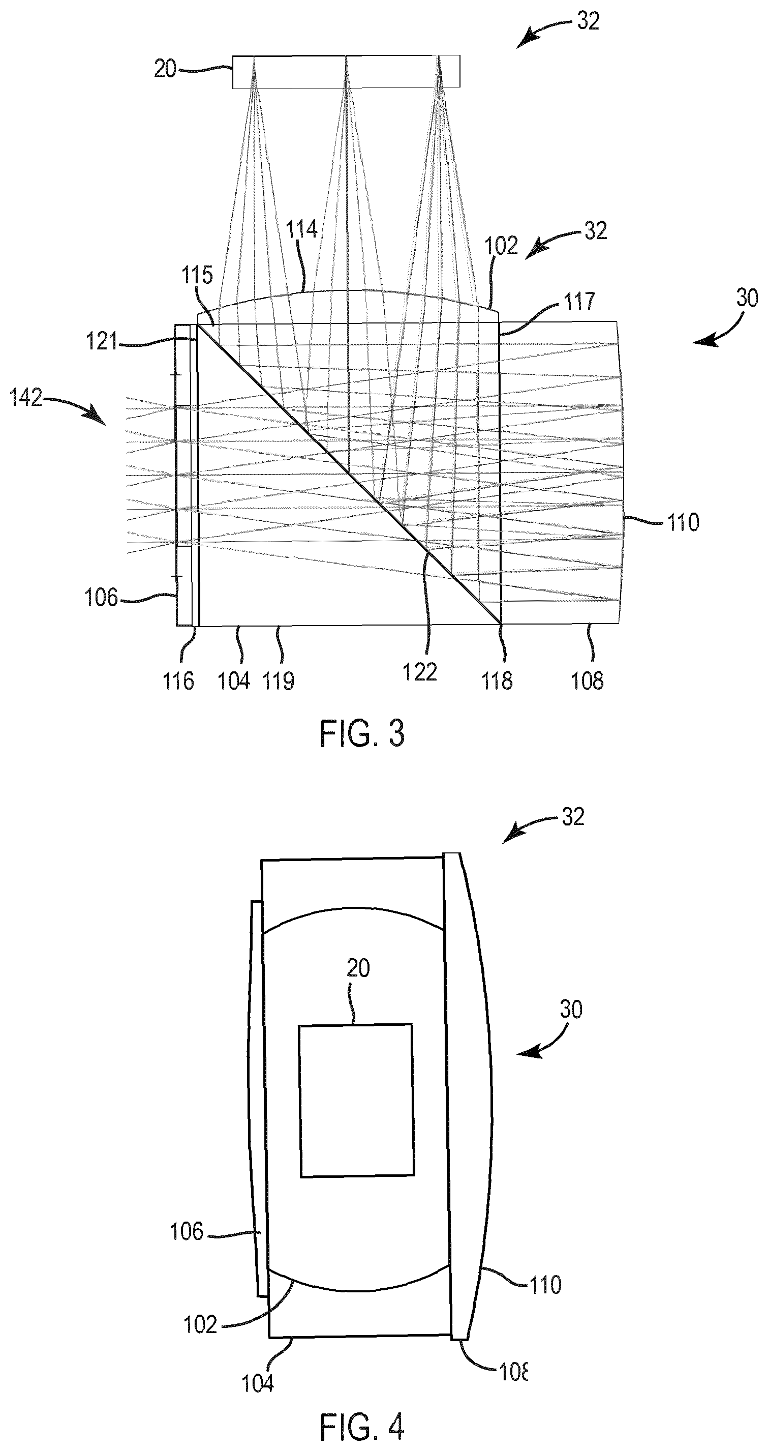
[0019] FIG. 3 is a side view schematic drawing of collimating optics for the HUD systems illustrated in FIGS. 1 and 2 in accordance with some exemplary embodiments of the inventive concepts disclosed herein;
[0020] FIG. 4 is a top view schematic drawing of the collimating optics illustrated in FIG. 3;
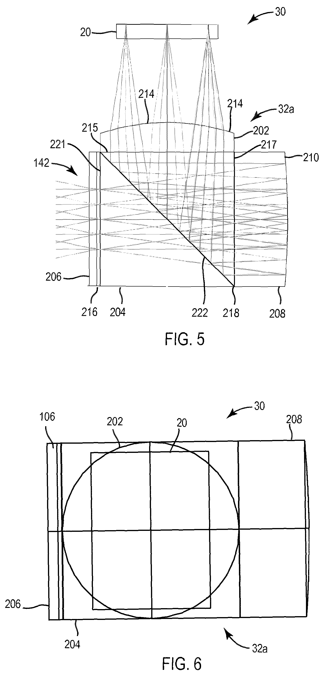
[0021] FIG. 5 is a side view schematic drawing of collimating optics for the HUD systems illustrated in FIGS. 1 and 2 in accordance with some exemplary embodiments of the inventive concepts disclosed herein;
[0022] FIG. 6 is a top view schematic drawing of the collimating optics illustrated in FIG. 5;
[0023] FIG. 7A is a side view schematic drawing of collimating optics for the HUD systems illustrated in FIGS. 1 and 2 in accordance with some exemplary embodiments of the inventive concepts disclosed herein;
[0024] FIG. 7B is a side view schematic drawing of collimating optics for the HUD systems, illustrations in FIGS. 1 and 2 in accordance with exemplary embodiments of the inventive concepts disclosed herein;
[0025] FIG. 7C is a side view schematic drawing of collimating optics including a folded path before the field lens;
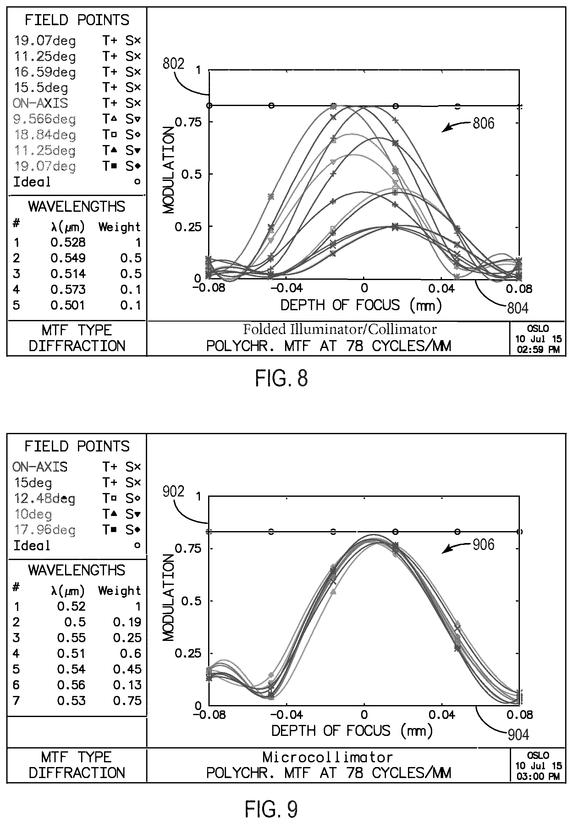
[0026] FIG. 8 is a chart showing resolution of a conventional projector; and
[0027] FIG. 9 is a chart showing resolution of the projector illustrated in FIG. 7 in accordance with some embodiments of the inventive concepts disclosed herein;
[0028] FIG. 10 is a front view schematic drawing of a waveguide for the HUD systems illustrated in FIGS. 1 and 2 in accordance with some exemplary embodiments of the inventive concepts disclosed herein;
[0029] FIG. 11 is a front view schematic drawing of a waveguide for the HUD systems illustrated in FIGS. 1 and 2 in accordance with some exemplary embodiments of the inventive concepts disclosed herein;
[0030] FIG. 12 is a perspective front view schematic drawing of a waveguide for the HUD systems illustrated in FIGS. 1 and 2 in accordance with some exemplary embodiments of the inventive concepts disclosed herein;
[0031] FIG. 13 is a perspective view schematic drawing of a waveguide for the HUD systems illustrated in FIGS. 1 and 2 in accordance with some exemplary embodiments of the inventive concepts disclosed herein; and
[0032] FIG. 14 is a perspective view schematic drawing of a waveguide for the HUD systems illustrated in FIGS. 1 and 2 in accordance with some exemplary embodiments of the inventive concepts disclosed herein.
DETAILED DESCRIPTION
[0033] Before describing in detail the particular improved system and method, it should be observed that the inventive concepts disclosed herein include, but are not limited to, a novel structural combination of optical components and not in the particular detailed configurations thereof. Accordingly, the structure, methods of manufacture and use, functions, control and arrangement of components have been illustrated in the drawings by readily understandable block representations and schematic drawings, in order not to obscure the disclosure with structural details which will be readily apparent to those skilled in the art, having the benefit of the description herein. Further, the inventive concepts disclosed herein are not limited to the particular embodiments depicted in the exemplary diagrams, but should be construed in accordance with the language in the claims.
[0034] In some embodiments, a collimator advantageously includes a field lens and a reflector mounted onto a cube, thereby allowing easy mechanical alignment of the field lens and the reflector under very tight tolerances. In some embodiments, a diffractive surface is added to the field lens to provide full color correction and to flatten the corrector lens so that the corrector lens becomes unnecessary. In some embodiments, the collimator is provided without a prism or other fold optics, thereby shortening the back focal length and improving performance while advantageously reducing size and weight. In some embodiments, a liquid crystal on silicon (LCOS) device is illuminated through an assembly of collimating optics to make the projector smaller. Careful polarization management can be provided through the use of a clean-up polarizer in the exit pupil when illuminating a LCOS device through the assembly in some embodiments. In some embodiments, the design of the collimating optics can be scaled to fields of view in excess of 40 degrees and to sizes smaller than 1 cm3. The collimating optics design is also compatible with organic light emitting diode (OLED) displays, active matrix liquid crystal display (AMLCDs), and other micro displays.
[0035] With reference to FIG. 1, a head up display (HUD) system 10 can be utilized in various applications, including aviation, medical, naval, targeting, ground based, military, etc. The term HUD as used herein refers to a fixed HUD, a near eye display, a worn display, a helmet mounted display or any type of display using a combiner for overlaying images from an image source over a real world scene. The HUD system 10 is configured for use in smaller cockpit environments and in worn display applications and yet provides an appropriate field of view and eye box for avionic applications in some embodiments. The HUD system 10 can be configured for use with worn components, such as, glasses, goggles, hats, helmets, etc. or be a HUD system with a fixed combiner in some embodiments.
[0036] The HUD system 10 includes a projector 30 and a substrate waveguide 40. The projector 30 provides light (an image) to the substrate waveguide 40 which operates as a combiner. The projector 30 includes an image source 20 and collimating optics 32. The projector 30 provides an image from the image source 20 and collimates the image via collimating optics 32 for display on the substrate waveguide 40. In some embodiments, the substrate waveguide 40 can be a reflective combiner or holographic combiner.
[0037] The image source 20 can be any device for providing an image including but not limited to a CRT display, a light emitting diode (LED) display, an organic light emitting diode (OLED) display, an active matrix liquid crystal display (AMLCD), a liquid crystal on silicon (LCOS) display, etc. In some embodiments, the image source 20 is a micro display and provides linearly polarized light (e.g., S or P polarized).
[0038] The collimating optics 32 are disposed between the substrate waveguide 40 and the image source 20. The collimating optics 32 can be a single optical component, such as a lens, or include multiple optical components. In one embodiment, the collimating optics 32 are configured as a catadioptric collimator. The collimating optics 32 are integrated with or spaced apart from image source 20 and/or substrate waveguide 40 in some embodiments.
[0039] In operation, the HUD system 10 provides images from the image source 20 via the collimating optics 32 to a pilot or other operator so that the pilot or other operator simultaneously views the images and a real world scene in some embodiments. The images can include graphic and/or text information (e.g., flight path vector, etc.) related to avionic information in some embodiments. In addition, the images can include synthetic or enhanced vision images. In some embodiments, collimated light representing the image from the image source 20 is provided on the substrate waveguide 40 so that the pilot can view the image conformally on the real world scene through the substrate waveguide 40. The substrate waveguide 40 is a translucent or transparent combiner for viewing the real world scene through main surfaces or sides 84 and 88 in some embodiments.
[0040] With reference to FIG. 1, the projector 30 and the user are disposed on respective opposing sides 84 and 88 of substrate waveguide 40 in some embodiments. Additionally, an input coupler 42 and an output coupler 44 are disposed on respective opposing sides 84 and 88 of substrate waveguide 40 in some embodiments. With reference to FIG. 2, the projector 30 and user can also be disposed on the same side 84 of the substrate waveguide 40 in some embodiments. Additionally, an input coupler 42 and an output coupler 44 can also be formed on the same side 84 of the substrate waveguide 40 in some embodiments.
[0041] With reference to FIGS. 3 and 4, the projector 30 includes an assembly of the collimating optics 32 disposed adjacent to or in the proximity of the image source 20 in some embodiments. In some embodiments, the collimating optics 32 provide a catadioptric collimator system and include a field lens 102, a beam splitter 104, a curved mirror 108, a corrector lens 106, a polarizer 116, and a film 118. The corrector lens 106 is disposed to provide collimated light to the input coupler 42 (FIG. 1) in some embodiments. The field lens 102 receives polarized light (e.g., an image) from the image source 20.
[0042] The beam splitter 104 is a polarizing beam splitter in a prismatic form in some embodiments. The beam splitter 104 includes a face 115, a face 117, a face 119, a face 121, and a polarization selective reflective surface 122 in some embodiments. The field lens 102 is disposed on the face 117, and the curved mirror 108 is provided on the face 119 (or is provided on the film 118 which is provided on the face 119) in some embodiments. The beam splitter 104 provides an internal folded optical path and includes the polarizer 116 provided on the face 121 in some embodiments.
[0043] The film 118 is a quarter wave retarder film in some embodiments. The film 118 controls the polarization states for efficient light transmission through the polarization selective reflective surface 122 of the beam splitter 104 in some embodiments. The polarizer 116 cleans up stray light in some embodiments.
[0044] The beam splitter 104 is a rectangular prism in single axis pupil expansion implementations of the HUD system 10 with an elongated sides extending into and out of the page in FIG. 3.
[0045] The field lens 102 includes a diffractive surface 114 and is configured as a plano-convex aspherical lens in some embodiments. The diffractive surface 114 is an aspheric surface processed by diamond grinding, etching, lithography, molding or other process to form diffractive grooves in some embodiments. The diffractive surface 114 provides color correction and higher order aberration control for the collimating optics 32 in some embodiments. The field lens 102 is manufactured from optical glass or plastic material in some embodiments.
[0046] The curved mirror 108 includes a curved reflective surface 110. The curved reflective surface 110 is a dichroic surface, a silvered, a metallic, or other reflecting surface and is curved to assist the collimation of light through the collimating optics 32. The curved mirror 108 provides an aspheric medium for reflective surface 110 and is manufactured from optical glass or plastic material in some embodiments. The combination of the field lens 102, the curved mirror 108, the beam splitter 104 and the corrector lens 106 serve to collimate light in some embodiments.
[0047] The corrector lens 106 is provided on the face 121 or on the polarizer 116 in some embodiments. The corrector lens 106 is manufactured from optical glass or plastic material in some embodiments. A retarder plate (e.g., similar to film 118) can be provided before or after the field lens 102 to effect a polarization change in some embodiments.
[0048] The light received at the face 115 of the beam splitter 104 from the image source 20 is reflected off the polarization selective reflective surface 122 within the beam splitter 104 to the face 117. Light travels from the face 117 through the film 118 to the curved mirror 108. The curved mirror 108 provides a catoptric element which in conjunction with a refractive (dioptric) element, such as, corrector lens 106, provides a catadioptric system in some embodiments. Reflective surface 110 can be modeled as an aspheric lens in some embodiments.
[0049] Light reflecting from the curved reflective surface 110 is provided through the film 118, the polarization selective reflective surface 122, and the polarizer 116 to the face 115. A combination of elements in the collimating optics 32 collimates light at an exit pupil 142 associated with the face 121 or the corrector lens 106. Applicants believe that the collimating optics 32 embodied as a catadioptric system advantageously assists in making the design of the HUD system 10 nearly 10 times smaller in volume than conventional designs in one embodiment. The assembly in some embodiments has a volume of less than 1 cubic centimeter.
[0050] The elements of the collimating optics 32 can be cemented together around beam splitter 104 to form a small, compact package. Mounting the field lens 102 and the curved mirror 108 directly to the beam splitter 104 or the film 118 provided on the beam splitter 104 provides mechanical alignment in very tight tolerances. Advantageously, the corrector lens 106 can have dimensions identical to dimensions associated with the face 115 of the beam splitter 104 such that easy alignment is obtained. Similarly, the field lens 102 and the curved mirror 108 can match the sizes of the respective faces 115 and 117.
[0051] The collimating optics 32 in FIGS. 3 and 4 are configured for use with single axis pupil expansion such as with the substrate waveguide 40 as shown in FIG. 10 in some embodiments. The collimating optics 32 discussed with reference to FIGS. 3 and 4 can also be used in dual axis expansion implementations in some embodiments.
[0052] With reference to FIGS. 5 and 6, the collimating optics 32a are similar to the collimating optics 32 discussed with reference to FIGS. 3 and 4. The collimating optics 32a include a field lens 202, a curved mirror 208, polarizing beam splitter 204 and a corrector lens 206. The corrector lens 206 is optional in some embodiments. The polarizing beam splitter 204 includes a polarization selective reflective surface 222 similar to a polarization selective reflective surface 122 (FIGS. 3 and 4). A film 218 is provided between the curved mirror 208 and the polarizing beam splitter 204 and is similar to the film 118.
[0053] The collimating optics 32a illustrated in FIGS. 5 and 6 are suitable for dual axis expansion such as dual axis expansion utilizing the substrate waveguide 40 illustrated in FIG. 11. The cone angles for the field lens 202 are smaller than the cone angles for the field lens 102 and are more suitable for use of the diffractive optical surface in some embodiments.
[0054] A cleanup polarizer 216 is provided between the corrector lens 206 and the polarizing beam splitter 204 (e.g., on a face 219). The corrector lens 206 is a flat cover glass for protecting polarizer 116 or beam splitter 104 in some embodiments. In some embodiments, the corrector lens 206 is not necessary due to the power of the curved reflective surface 110 and the field lens 102 with the diffractive surface 114. The components associated with the collimating optics 32a can be cemented together similar to collimating optics 32 discussed with reference to FIGS. 3-4. Mounting the field lens 202 and the curved mirror 208 directly to the polarizing beam splitter 204 or the film 218 provided on the polarizing beam splitter 204 provides mechanical alignment in very tight tolerances.
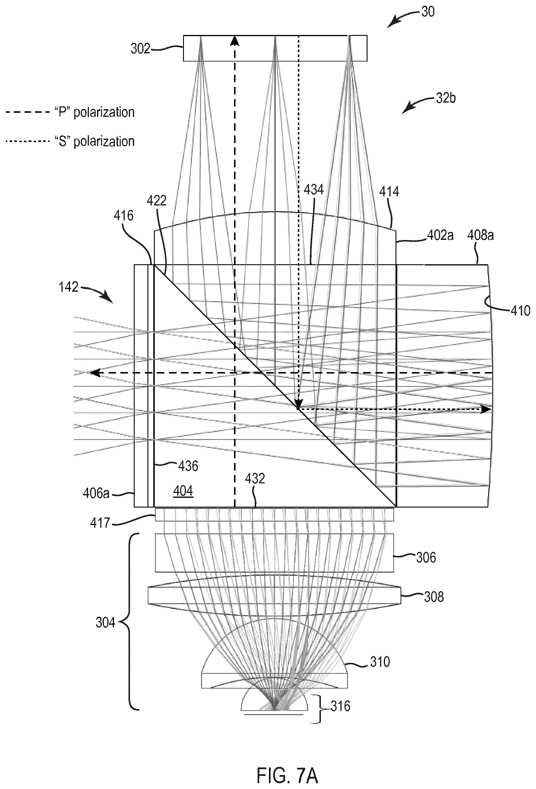
[0055] With reference to FIG. 7A, the projector 30 includes collimating optics 32b, a LCOS display 302 and an illuminator 304 in some embodiments. The illuminator 304 includes a Fresnel lens 306, a convex lens 308, a dome lens 310, and a LED 316 in some embodiments. Light is provided from the LED 316 through the dome lens 310, the convex lens 308, and the Fresnel lens 306 to the collimating optics 32. Using the image source 20 and the illuminator 304 provides an even smaller package for the projector 30 in some embodiments.
[0056] The collimating optics 32b shown in FIG. 7A are similar to the collimating optics 32 and 32a discussed with reference to FIGS. 3-6. The collimating optics 32b include a field lens 402a (similar to the field lens 202), a beam splitter 404 (similar to the beam splitter 204), a curved mirror 408a (similar to the curved mirror 208), a corrector lens 406 (similar to the corrector lens 206), and a pre-polarizer 417. The beam splitter 404 is a polarizing beam splitter disposed between the illuminator 304 and the LCOS micro display 302 in some embodiments.
[0057] The pre-polarizer 417 is provided on a face 432 of the beam splitter 404. Light from the Fresnel lens 306 is polarized in a particular state (e.g., S or P polarized light) by the pre-polarizer 417 and provided to the LCOS micro display 302. The beam splitter 404 includes a polarization selective reflective surface 422 between the face 432 and a face 434. Polarized light of a first state is provided through the polarization selective reflective surface 422 to the LCOS micro display 302. The LCOS micro display 302 provides an image to the field lens 402a. The field lens 402a includes a diffractive surface 414 similar to the diffractive surface 214 (FIG. 3).
[0058] The LCOS micro display 302 changes the polarization of the light received from the face 434 of beam splitter 404 to a second state (e.g., S or P polarized light). Light passes through the face 434 and strikes the polarization selective reflective surface 422 and is reflected toward a curved reflective surface 410 of the curved mirror 408a. As light travels through a retarder film 418, the polarization of the light is changed. As light is reflected from the curved reflective surface 410, it passes back through the retarder film 418 and becomes polarized back to the first state and passes through the polarization selective reflective surface 422. The light exits a face 436 of the beam splitter 404 and passes through the corrector lens 406 which is optional. A clean up polarizer 416 is provided between the corrector lens 406 and the beam splitter 404 at the face 436 of the beam splitter 44 in some embodiments. Collimating optics 32b is suitable for dual pupil expansion designs in some embodiments.
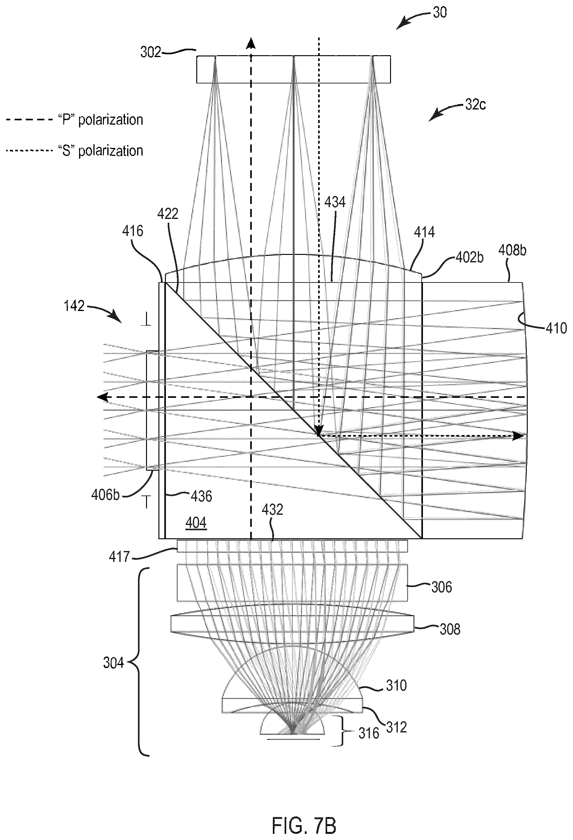
[0059] With reference to FIG. 7B, the projector 30 includes the image source 20 and the collimating optics 32c in some embodiments. The image source 20 includes the LCOS micro display 302 and the illuminator 304.
[0060] The collimating optics 32c shown in FIG. 7B are similar to the collimating optics 32, 32a and 32b discussed with reference to FIGS. 3-7A. The collimating optics 32c include a field lens 402b (similar to the field lens 102), the beam splitter 404 (similar to the beam splitter 104), a curved mirror 408b (similar to the curved mirror 108), the corrector lens 406 (similar to the corrector lens 106), and the pre-polarizer 417. Collimating optics 32c is suitable for single axis pupil expansion designs in some embodiments.
[0061] The assembly of the collimating optics 32, 32a, 32b and 32c as embodied in FIGS. 3, 5, 7A and 7B advantageously provides a relatively low optical element count with a short focal length in some embodiments. The F ratio (the ratio of pupil diameter to focal length) is kept very low in some embodiments. In addition, the assembly of the collimating optics 32, 32a, 32b, and 32c as embodied in FIGS. 3, 5 and 7A and 7B efficiently handles polarized light and provides a compact high performance collimating solution.
[0062] As shown in FIGS. 3-7B, the collimating optics 32, 32a, 32b, and 32c uses a combination of low-ratio reflective optics in an on-axis arrangement with the beam splitters 104, 204, and 404 and the exit pupil 142 being truncated in some embodiments. The low-ratio optics provides the advantage of achieving a high optical efficiency in a small volume in some embodiments. The on-axis arrangement allows excellent aberration correction and low element count in some embodiments. The reflective optics provide low chromatic dispersion and the beam splitter 104 allows the collimating optics 32, 32a, 32b, and 32c to be used on axis (no tilted or de-centered elements) in some embodiments. Fold optical elements are advantageously not required by the collimating optics 32, 32a, 32b, and 32c which simultaneously provide both collimation and efficient handling of polarization states in some embodiments.
[0063] In some embodiments, the collimating optics 32, 32a, 32b, and 32c provide a 30 degree field of view from the image source 20 embodied as a 9.4 millimeters. diagonal LCOS display which translates into a focal length of approximately 13 millimeters. Eliminating the use of a folded prism path shortens back focal length and improves the performance while reducing size and weight in some embodiments. Fields of view in excess of 40 degrees using the collimating optics 32, 32a, 32b, and 32c having a size of less than 1 cubic centimeter are possible in some embodiments. The design of the collimating optics 32, 32a, 32b, and 32c is also compatible with OLED, AMLCD, or other micro displays.
[0064] With reference to FIG. 7C, a projector 500 includes collimating optics 501, a LCOS display 502, and an illuminator 504. The illuminator 504 includes a Fresnel lens 506, a convex lens 508, dome lens 510, and a LED 516. The illuminator 504 also includes a beam splitter 514 having a polarization sensitive reflective coating 515, a polarizer 518, and a retarder 519. The polarizer 518 is disposed between the lens 506 and the polarizing beam splitter 514. Light from the LED 516 is provided through, the dome lens 510, the convex lens 508, the lens 506, the polarizer 518, the polarizing beam splitter 514 including the polarization sensitive reflective coating 515, and the retarder 519 to the LCOS micro display 502.
[0065] An image reflected off the LCOS micro display 502 is provided through the retarder 519 and the light has a polarization such that the light that is reflected by polarization sensitive reflective coating 515 to the collimating optics 501. The collimating optics 501 include a field lens 602, a polarizing beam splitter 604, a curved reflective element 608, a quarter wave retarder film 618, and a correcting lens 606. A half wave retarder film 610 is provided between corrected lens 606 and polarizing beam splitter 604. The field lens 602 is generally spatially separate from the polarizing beam splitter 604 and is larger than the field lenses 102, 202, 402A, and 402B (FIGS. 3-7B).
[0066] With reference to FIG. 8, an X axis 804 represents focus in inches and a Y axis 802 represents the modulation transfer function weighted across LED spectral weights which is an indication of contrast. A set of curves 806 at various angles demonstrates resolution for the collimating optic 501 of FIG. 7C. With reference to FIG. 9, a Y axis 902 represents the modulation transfer function weighted across LED spectral weights which is an indication of contrast and an X axis 904 represents focus in millimeters. A set of curves 906 at various angles shows better resolution for the collimating optics 32b of FIG. 7A at the same effective aperture as the collimating optics 501 of FIG. 7C. The projector 500 including fold optics (the beam splitter 514) before the field lens 602 provides a polychromic modulation transfer function of 20 cycles per millimeter while the polychromic modulation transfer function for the projector 30 including the collimating optics 32b of FIG. 7A is 78 cycles per millimeter in some embodiments.
[0067] With reference to FIGS. 1 and 10, the substrate waveguide 40 includes an input coupler (e.g., a diffraction grating) 42 and an output coupler (e.g. a diffraction grating) 44. In some embodiments, the input coupler 42 and the output coupler 44 are comprised of surface relief gratings, volume gratings (e.g. holographic gratings), reflective arrays, etc. In some embodiments, the substrate waveguide 40 of FIG. 10 effects the single axis pupil expansion.
[0068] With reference to FIG. 11, the substrate waveguide 40 is configured for dual axis pupil expansion and includes the input coupler 42, a fold grating 50, and the output coupler 44 in some embodiments. The fold grating 50 expands the pupil in a first direction (e.g., vertically) and the output coupler 44 expands the pupil in a second direction (e.g., horizontally) in some embodiments. In some embodiments, the input coupler 42, fold grating 50 and output coupler 44 are comprised of surface relief gratings, volume gratings (e.g. holographic gratings), reflective arrays, etc. In some embodiments, the input coupler 42 is a surface relief grating and the fold grating 50 and the output coupler 44 are volume holograms.
[0069] In some embodiments, two layers of waveguides are used to provide dual axis expansion utilizing cross gratings. Each layer expands in the pupil in one direction. Dual axis expansion using waveguides is discussed in U.S. Pat. No. 8,736,963, incorporated herein by reference in its entirety.
[0070] With reference to FIG. 12, a waveguide system 1200 can be used as the substrate waveguide 40 (FIG. 1). A projector, such as the projector 30, can be used with the waveguide system 1200 or the waveguide systems discussed in U.S. patent application Ser. No. 14/715,332 invented by Brown et al. and filed May 18, 2015 and incorporated herein by reference in its entirety. The waveguide system 1200 is similar to the waveguides discussed in U.S. patent application Ser. No. 14/715,332. The waveguide system 1200 provides dual axis pupil expansion in some embodiments. In some embodiments, the waveguide system 1200 is configured as a fixed combiner or as a worn combiner.
[0071] In some embodiments, the waveguide system 1200 includes an input block 1202, a light pipe 1204 and a waveguide 1206. The input block 1202 includes an input coupler or input grating 1222 and a turn grating 1223 (e.g., a fold grating). The input grating 1222 is disposed on a top portion of the XY face of input block 1202 in some embodiments. The light pipe 1204 includes a turn grating 1226. In some embodiments, the turn grating 1223 is provided on the light pipe 1204 or between the light pipe 1204 and the input block 1202. The waveguide 1206 includes an output grating 1224 which is placed on an XY face (or its parallel) of the waveguide 1206 in some embodiments.
[0072] In some embodiments, the input grating 1222 couples light from the projector 30 (FIG. 1) into the input block 1202 (e.g., light provided to an XY face of the input block 1202 is turned substantially along the Y direction). The turn grating 1223 is configured to turn the light for entry into the light pipe 1204 (e.g., cause the light to travel substantially along the X direction and maintaining total internal reflection on the XZ faces of the light pipe 1204). The light propagates down the light pipe 1204 by mirror reflection or total internal reflection until it reaches the turn grating 1226 on an XZ face of the light pipe 1204 where the light is turned toward the waveguide 1206 (e.g., propagates substantially in the Y direction).
[0073] The turn grating 1226 is a reciprocal turn grating (e.g., kx2 with grating lines parallel to Z) to the turn grating 1223 (e.g., ky1 with grating lines parallel to X) and disposed along the expansion path in some embodiments. The turn grating 1226 is a gradient turn grating in some embodiments. The output grating 1224 is a reciprocal grating to the input grating 1222 in some embodiments.
[0074] The light is expanded down the waveguide 1206 and is extracted along the Z axis by the output grating 1224 in some embodiments. The output grating 1224 is a reciprocal grating to the input grating 1222 and diffracts light out of the waveguide 1206 with no dispersion in some embodiments. The light pipe 1204 provides pupil expansion in the horizontal direction and the output grating 1224 provides pupil expansion in the vertical direction (the axes of expansion are at 90 degree angle in some embodiments).
[0075] The input grating 1222, the turn grating 1223, the turn grating 1226, and the output grating 1224 can be placed on or within the local planes of the light pipe 1204 and the waveguide 1206. In some embodiments, there is an air gap or low index of refraction material between the light pipe 1204 and the waveguide 1206. The input grating 1222, the turn grating 1226, and the output grating 1224 can be any type of light couplers including but not limited to volume holograms, replicated gratings or surface relief gratings. The input grating 1222 is a reflection type grating in some embodiments. In some embodiments, the input grating 1222 is a transmission type grating. In some embodiments, the light pipe 1204 injects light into waveguide 1206 along a top edge 1232 of the waveguide 1206 via a bottom edge 1234 of the light pipe 1204. The gratings, 1223 and 1226 can be replaced with a properly designed mirror or mirror arrays. The dispersion compensation can be lost depending on specific arrangement.
[0076] The light pipe discussed in U.S. patent application Ser. No. 14/715,332 does not necessarily provide pupil expansion in the waveguide (e.g., along the second direction) at an angle of 90 degrees with respect to the first direction of pupil expansion which can lead to a vignetted view in the monocular eye box in some embodiments. The pupil expansion technique discussed in U.S. patent application Ser. No. 14/715,332 expands the light along two axes but only dispersed the light along one axis in some embodiments. This produces a banding structure in the eye box of the display, similar to a narrow band source single axis expansion, such as using laser illumination, in some embodiments. The waveguide system 1200 achieves close to a 90 degree angle between the two directions of pupil expansion therefore providing a compact and high efficiency system with large unvignetted eye box with dispersion compensation.
[0077] In some embodiments, a gradient beam splitter and a high efficiency turn grating is provided in a plane parallel to the XZ plane and in the light pipe 1204 instead of the turn grating 1226. In some embodiments, an input port is provided on the light pipe 1204 instead of the input block 1202. The input port is an input grating on the XY surface of the light pipe 1204 and works in reflection mode in some embodiments. The input port is a kinoform mirror or a mirror array (without dispersion property) in some embodiments. In some embodiments, the turn grating 1226 is replaced by a mirror array in parallel or mirrored orientation. The mirrors are partial reflectors with angular dependent coating to avoid ghost reflections in some embodiments. In some embodiments, the mirror array for the input is removed and the input grating is rotated in-plane to send the spiral ray down the light pipe 1204. In some embodiments, for dispersion compensation, the gratings at the input of the light pipe 1204 and at the output in the waveguide 1206 are matched in pitch and mirrored by the turning mirror array. In some embodiments, the turning grating/mirrors is made gradient to allow controlled light output from the light pipe 1204 into the waveguide 1206.
[0078] In some embodiments, the light pipe 1204 is joined to the waveguide 1206 by a low index material. The low index material acts as a cladding layer, isolating the light pipe 1204 from the waveguide 1206 until the beam has diffracted from the turn grating 1226.
[0079] With reference to FIG. 13, a waveguide system 1300 can be used as the substrate waveguide 40 (FIG. 1). A projector, such as the projector 30, can be used with the waveguide system 1300. The waveguide system 1300 is similar to the waveguide system 1200 (FIG. 12) and provides dual axis pupil expansion in some embodiments.
[0080] In some embodiments, the waveguide system 1300 includes a light pipe 1304 and a waveguide 1306. The light pipe 1304 includes an input coupler or input grating 1322, and an optional pair of mirror symmetric turn gratings 1326 and 1328 (e.g., on XY faces (or their parallel) of the light pipe 1304). In some embodiments, only one of the mirror symmetric turn gratings 1326 and 1328 is utilized. The input grating 1322 is on the XY face of the light pipe 1304 in some embodiments. The waveguide 1306 includes an output grating 1324 which is disposed on an XY face (or its parallel) of the waveguide 1306 in some embodiments.
[0081] In some embodiments, the light pipe 1304 is joined to the waveguide 1306 by a low index material. The low index material acts as a cladding layer, isolating the light pipe 1304 from the waveguide 1306 until the beam has diffracted from at least one of the turn gratings 1326 and 1328.
[0082] In some embodiments, the input grating 1322 has both x and y k-vector orientation. The turn gratings 1326 and 1328 have both components, such that the rotation angle of the k-vector will diffract the ray substantially along the local Y direction. The turn gratings 1326 and 1328 can be used to pick up the mirror-symmetric ray if desired. The output grating 1324 has a k-vector that is oriented so that the sum rotation angle is zero in some embodiments.
[0083] In some embodiments, the input and output gratings 1322 and 1324 are on either side of the light pipe 1304 and the waveguide 1306 in the XY plane. In some embodiments, the turn gratings 1326 and 1328 can be on any of the four surfaces of the light pipe 1304 (e.g., in both the XY and XZ planes. The gratings 1322, 1324, 1326, and 1328 are either surface mounted or imbedded in some embodiments.
[0084] With reference to FIG. 14, a waveguide system 1400 can be used as the substrate waveguide 40 (FIG. 1). A projector, such as the projector 30, can be used with the waveguide system 1400. The waveguide system 1400 is similar to the waveguide system 1200 (FIG. 12) and provides dual axis pupil expansion in some embodiments.
[0085] In some embodiments, the waveguide system 1400 includes a light pipe 1402, a light pipe 1404 and a waveguide 1406. The light pipe 1402 includes an input coupler or input grating 1422, and the light pipe 1404 includes a turn grating 1426 (e.g., on an XY face (or its parallel) of the light pipe 1404). The input grating 1422 is on the XY face of the light pipe 1402 in some embodiments. The waveguide 1406 includes an output grating 1424 which is placed on an XY face (or its parallel) of the waveguide 1406 in some embodiments.
[0086] A gradient reflection coating is provided at an interface of the light pipes 1402 and 1404 in some embodiments. In some embodiments, the turn grating 1426 is one or two highly efficient mirror symmetric gratings on one or two of the XY faces of the light pipe 1404 that diffracts and turns the light substantially along the Y direction.
[0087] In some embodiments, the input and output gratings 1422 and 1424 are on either side of the light pipe 1404 and the waveguide 1406 in the XY plane. In some embodiments, one or more gratings, such as the turn grating 1426, can be on any of the four surfaces of the light pipe 1404 (e.g., in both the XY and XZ planes). The gratings 1422, 1424, and 1426, are either surface mounted or imbedded in some embodiments.
[0088] It is understood that while the detailed drawings, specific examples, material types, thicknesses, dimensions, and particular values given provide a preferred exemplary embodiment of the present invention, the preferred exemplary embodiment is for the purpose of illustration only. The method and apparatus of the invention is not limited to the precise details and conditions disclosed. For example, although specific types of optical component, shapes, dimensions and angles are mentioned, other components, dimensions and angles can be utilized. Various changes may be made to the details disclosed without departing from the spirit of the invention which is defined by the following claim.
* * * * *
D00000
D00001
D00002
D00003
D00004
D00005
D00006
D00007
D00008
D00009
XML
uspto.report is an independent third-party trademark research tool that is not affiliated, endorsed, or sponsored by the United States Patent and Trademark Office (USPTO) or any other governmental organization. The information provided by uspto.report is based on publicly available data at the time of writing and is intended for informational purposes only.
While we strive to provide accurate and up-to-date information, we do not guarantee the accuracy, completeness, reliability, or suitability of the information displayed on this site. The use of this site is at your own risk. Any reliance you place on such information is therefore strictly at your own risk.
All official trademark data, including owner information, should be verified by visiting the official USPTO website at www.uspto.gov. This site is not intended to replace professional legal advice and should not be used as a substitute for consulting with a legal professional who is knowledgeable about trademark law.