Wide Angle Lens And Camera System For Peripheral Field Of View Imaging
MAKEEV; Maksim ; et al.
U.S. patent application number 16/617277 was filed with the patent office on 2020-06-18 for wide angle lens and camera system for peripheral field of view imaging. The applicant listed for this patent is Owl Labs, Inc.. Invention is credited to Chien-Hung CHOU, Cheng-Yi Lai, Ming-lin LEE, Maksim MAKEEV, Xiaoyu MIAO, Mark S SCHNITTMAN.
| Application Number | 20200192069 16/617277 |
| Document ID | / |
| Family ID | 64455023 |
| Filed Date | 2020-06-18 |
View All Diagrams
| United States Patent Application | 20200192069 |
| Kind Code | A1 |
| MAKEEV; Maksim ; et al. | June 18, 2020 |
WIDE ANGLE LENS AND CAMERA SYSTEM FOR PERIPHERAL FIELD OF VIEW IMAGING
Abstract
Wide angle lens for imaging objects disposed away from the optical axis towards the periphery of the field of view.
| Inventors: | MAKEEV; Maksim; (Somerville, MA) ; SCHNITTMAN; Mark S; (Somerville, MA) ; MIAO; Xiaoyu; (Palo Alto, CA) ; LEE; Ming-lin; (Taipei City, TW) ; Lai; Cheng-Yi; (Taipei City, TW) ; CHOU; Chien-Hung; (Taipei City, TW) | ||||||||||
| Applicant: |
|
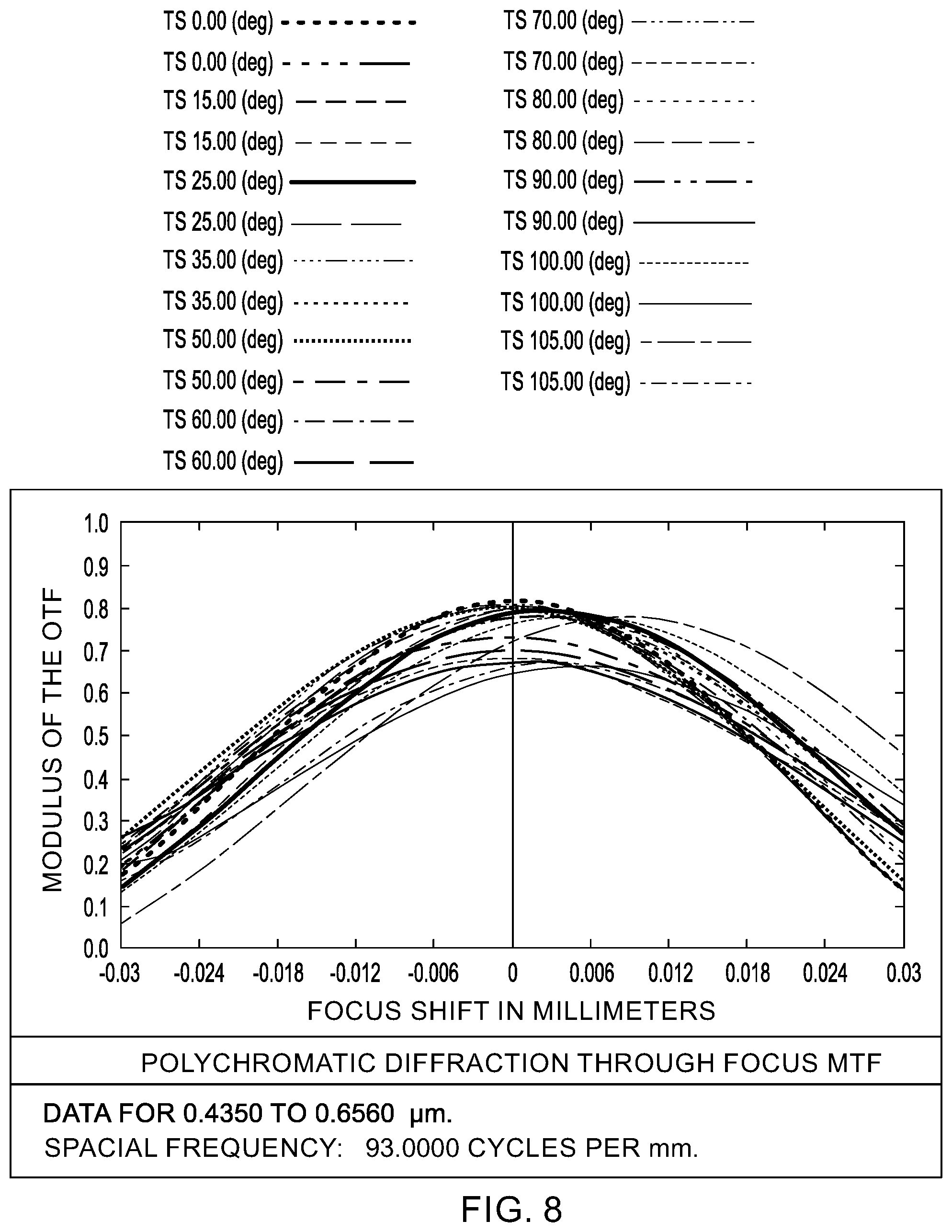
||||||||||
|---|---|---|---|---|---|---|---|---|---|---|---|
| Family ID: | 64455023 | ||||||||||
| Appl. No.: | 16/617277 | ||||||||||
| Filed: | May 31, 2018 | ||||||||||
| PCT Filed: | May 31, 2018 | ||||||||||
| PCT NO: | PCT/US18/35328 | ||||||||||
| 371 Date: | November 26, 2019 |
Related U.S. Patent Documents
| Application Number | Filing Date | Patent Number | ||
|---|---|---|---|---|
| 62514080 | Jun 2, 2017 | |||
| Current U.S. Class: | 1/1 |
| Current CPC Class: | G02B 13/06 20130101; G02B 13/04 20130101 |
| International Class: | G02B 13/06 20060101 G02B013/06 |
Claims
1. A wide angle lens for imaging objects disposed in a region of interest of the field of view, comprising in order along an optical axis from object to image space: a first group of lens elements, an aperture stop, and a second group of lens elements, wherein the region of interest is an annular cone that extends between a first angle of at least 30 degrees from the optical axis to a second angle of at least 75 degrees from the optical axis, and wherein the first and second lens groups are configured for imaging of objects disposed within the region of interest.
2. The wide angle lens of claim 1, wherein the second angle is at least twice the first angle.
3. The wide angle lens of claim 1, wherein the ratio of the second angle to the first angle, R, is in the range of R=1.67:1 to 2.5:1.
4. The wide angle lens of claim 3, wherein the lens in configured and constructed such that a ray of the second angle in object space intersects the lens image plane at a distance, H, from the optical axis and a ray of the first angle in object space intersects the lens image plane at a distance, h, from the optical axis such that H/h>R, or preferably H/h.gtoreq.1.1.times.R, or more preferably H/h.gtoreq.1.5.times.R.
5. The wide angle lens of claim 3, wherein R=2.
6. The wide angle lens of claim 1, wherein the first angle is 45 degrees.
7. The wide angle lens of claim 1, wherein the first angle is 50 degrees.
8. The wide angle lens of claim 1, wherein the first angle is 50 degrees and the second angle is 100 degrees.
9. The wide angle lens of claim 1, wherein the first and second groups of lens elements are configured for imaging of objects disposed within the region of interest by having a longitudinal spherical aberration on-axis is greater than the longitudinal spherical aberration throughout the region of interest.
10. The wide angle lens of claim 1, wherein the first and second groups of lens elements are configured for imaging of objects disposed within the region of interest by having a longitudinal spherical aberration throughout the region of interest less than half of the longitudinal spherical aberration on-axis.
11. The wide angle lens of claim 1, wherein the first and second groups of lens elements are configured for imaging of objects disposed within the region of interest by having a field curvature for tangential rays on-axis greater than the field curvature for tangential rays throughout the region of interest.
12. The wide angle lens of claim 1, wherein the first and second groups of lens elements are configured for imaging of objects disposed within the region of interest by having a field curvature for tangential rays throughout the region of interest less than one quarter of the field curvature for tangential rays on-axis.
13. The wide angle lens of claim 1, wherein the first and second groups of lens elements are configured for imaging of objects disposed within the region of interest by having a modulation transfer function of at least 55% at 187 lp/mm for sagittal rays in the region of interest.
14. The wide angle lens of claim 1, wherein the first and second groups of lens elements are configured for imaging of objects disposed within the region of interest by having a modulation transfer function of at least 76% at 93 lp/mm for sagittal rays in the region of interest.
15. The wide angle lens of claim 1, wherein the first and second groups of lens elements are configured for imaging of objects disposed within the region of interest by having a modulation transfer function of at least 36% at 187 lp/mm for tangential rays in the region of interest.
16. The wide angle lens of claim 1, wherein the first and second groups of lens elements are configured for imaging of objects disposed within the region of interest by having a modulation transfer function of at least 65% at 93 lp/mm for tangential rays in the region of interest.
17. The wide angle lens of claim 1, wherein the lens elements of the first and second groups all have spherical surfaces.
18. The wide angle lens of claim 1, wherein the first group of lens elements consists of four or five lenses.
19. The wide angle lens of claim 1, wherein the second group of lens elements consists of four lenses.
20. The wide angle lens of claim 1, wherein the effective focal length is 1 mm or less.
21. The wide angle lens of claim 1, wherein the f-number is 2.4 or less.
22. The wide angle lens of claim 1, wherein the f-theta distortion is 34% or less at full field.
23. The wide angle lens of claim 1, wherein the chief ray angle at the image plane of the wide angle lens is less than 4.5 degrees from a normal to the surface at the image plane.
24. The wide angle lens of claim 1, wherein the back focal length is 1 mm or less.
25. The wide angle lens of claim 1, wherein a lens element closest to the aperture stop from the first group of elements contributes to the correction of third order field curvature.
26. The wide angle lens of claim 1, wherein a lens element of the second group of elements contributes to the correction of third order field curvature.
27. The wide angle lens of claim 1, wherein angular mapping of the field of view in the region of interest onto the image plane is substantially linear.
28. A wide angle lens having an angular field of view, FOV, of more than 150 degrees spanning the optical axis and a central half-field of view, FOV.sub.1/2, spanning the optical axis such that a ratio of the angular range FOV.sub.1/2 of the central half field of view versus the angular range of the field of view FOV is FOV/FOV.sub.1/2=2, the lens being constructed and arranged such that a ratio of a diameter (D.sub.1) at the image plane of an image circle of the field of view versus the diameter (D.sub.1/2) of an image circle of the central half-field of view is D.sub.1/D.sub.1/2>2.
29. A wide angle lens of claim 28 wherein D.sub.1/D.sub.1/2.gtoreq.2.2, or preferably D.sub.1/D.sub.1/2.gtoreq.2.5, or more preferably D.sub.1/D.sub.1/2.gtoreq.3.
30. The wide angle lens of claim 28, comprising a region of interest disposed between the FOV.sub.1/2 and FOV, wherein angular mapping of the field of view in the region of interest onto the image plane is substantially linear.
31. The wide angle lens of claim 28, comprising a region of interest disposed between the FOV.sub.1/2 and FOV, wherein the lens has a longitudinal spherical aberration on-axis greater than the longitudinal spherical aberration throughout the region of interest.
32. The wide angle lens of claim 28, comprising a region of interest disposed between the FOV.sub.1/2 and FOV, wherein the lens has a longitudinal spherical aberration throughout the region of interest less than half of the longitudinal spherical aberration on-axis.
33. The wide angle lens of claim 28, comprising a region of interest disposed between the FOV.sub.1/2 and FOV, wherein the lens has a field curvature for tangential rays on-axis greater than the field curvature for tangential rays throughout the region of interest.
34. The wide angle lens of claim 28, comprising a region of interest disposed between the FOV.sub.1/2 and FOV, wherein the lens has a field curvature for tangential rays throughout the region of interest less than one quarter of the field curvature for tangential rays on-axis.
35. The wide angle lens of claim 28, comprising a region of interest disposed between the FOV.sub.1/2 and FOV, wherein the lens has a modulation transfer function of at least 55% at 187 lp/mm for sagittal rays in the region of interest.
36. The wide angle lens of claim 28, comprising a region of interest disposed between the FOV.sub.1/2 and FOV, wherein the lens has a modulation transfer function of at least 76% at 93 lp/mm for sagittal rays in the region of interest.
37. The wide angle lens of claim 28, comprising a region of interest disposed between the FOV.sub.1/2 and FOV, wherein the lens has a modulation transfer function of at least 36% at 187 lp/mm for tangential rays in the region of interest.
38. The wide angle lens of claim 28, comprising a region of interest disposed between the FOV.sub.1/2 and FOV, wherein the lens has a modulation transfer function of at least 65% at 93 lp/mm for tangential rays in the region of interest.
39. The wide angle lens of claim 28, wherein the lens comprises all spherical surfaces.
40. The wide angle lens of claim 28, wherein the effective focal length is 1 mm or less.
41. The wide angle lens of claim 28, wherein the f-number is 2.4 or less.
42. The wide angle lens of claim 28, wherein the f-theta distortion is 34% or less at full field.
43. The wide angle lens of claim 28, wherein the chief ray angle at an image plane of the wide angle lens is less than 4.5 degrees from a normal to the surface at the image plane.
44. The wide angle lens of claim 28, wherein the back focal length is 1 mm or less.
45. The wide angle lens of claim 28, wherein the full field of view spanning the optical axis is 200 degrees.
46. A camera system comprising the wide angle lens according to claim 1 and comprising an image sensor having an imaging surface area placed at the back focal length of the lens.
Description
RELATED APPLICATIONS
[0001] This application claims the benefit of priority of U.S. Provisional Application No. 62/514,080, filed on Jun. 2, 2017, the entire contents of which application(s) are incorporated herein by reference.
FIELD OF THE INVENTION
[0002] The present invention relates generally to wide angle lenses, and more particularly, but not exclusively, to lenses configured to preferentially image objects located towards the periphery of the field of view, as well as camera systems incorporating such lenses.
BACKGROUND OF THE INVENTION
[0003] Axiomatic to optical imaging systems is the principle that such systems are designed with the expectation that objects of primary interest will be located on the optical axis of the imaging system, and therefore lenses of such systems must be designed to provide high quality imaging on-axis. Indeed, one will typically accept reduced optical performance at the edges of the field of view in favor of enhanced performance on-axis. Photography, microscopy, and astronomy are all examples of fields in which the observer often endeavors to position the optical system so that at least one object of interest is disposed centrally in the field of view on the optical axis.
[0004] In contrast, Applicant has conceived of applications in which all objects of interest will be disposed away from the optical axis towards the periphery of the field of view. Consequently, Applicant has recognized that existing lenses which are optimized for on-axis performance are not well-suited to peripheral field of view imaging in part due to the unneeded optimization of on-axis-performance. Accordingly, it would be an advance in the state-of-the-art to provide wide angle lenses which are optimized for imaging objects located at the periphery of the field of view rather than on-axis.
SUMMARY
[0005] In accordance with one of its aspects, the present invention may provide a wide angle lens for imaging objects disposed in a peripheral region of interest of the field of view. An exemplary wide angle lens in accordance with the present invention may include, in order along an optical axis from object to image space, a first group of lens elements, an aperture stop, and a second group of lens elements. The region of interest may be an annular cone that extends between a first angle of at least 30 degrees from the optical axis to a second angle of at least 75 degrees from the optical axis, where the first and second lens groups are configured for imaging of objects disposed within the region of interest. The wide angle lens may have a ratio of the first angle to the second angle in the range of R=1.67:1 to 2.5:1. In particular, the first angle may be 50 degrees and the second angle may be 100 degrees. The lens may be configured and constructed such that a ray of the second angle in object space intersects the lens image plane at a distance, H, from the optical axis and a ray of the first angle in object space intersects the lens image plane at a distance, h, from the optical axis such that H/h>R, or preferably H/h.gtoreq.1.1.times.R, or more preferably H/h.gtoreq.1.5.times.R The angular mapping of the field of view in the region of interest onto the image plane may be substantially linear.
[0006] The first and second groups of lens elements may be configured for imaging of objects disposed within the region of interest by having certain performance metrics in the region of interest. For example, the first and second groups of lens elements may cooperate to provide: a longitudinal spherical aberration on-axis greater than the longitudinal spherical aberration throughout the region of interest; a longitudinal spherical aberration throughout the region of interest less than half of the longitudinal spherical aberration on-axis; a field curvature for tangential rays on-axis greater than the field curvature for tangential rays throughout the region of interest; and/or a field curvature for tangential rays throughout the region of interest less than one quarter of the field curvature for tangential rays on-axis.
[0007] Further, the first and second groups of lens elements may cooperate to provide: a modulation transfer function of at least 55% at 187 lp/mm for sagittal rays in the region of interest; a modulation transfer function of at least 76% at 93 lp/mm for sagittal rays in the region of interest; a modulation transfer function of at least 36% at 187 lp/mm for tangential rays in the region of interest; and/or a modulation transfer function of at least 65% at 93 lp/mm for tangential rays in the region of interest. Also of note, exemplary wide angle lenses in accordance with the present invention may be optimized without the use of aspherical surfaces; the lens elements of the first and second groups may all have spherical surfaces. The first group of lens elements may consist of four or five lenses, while the second group of lens elements may consist of four lenses. The effective focal length may be 1 mm or less with an f-number of 2.4 or less.
[0008] In another of its aspects, the present invention may provide a wide angle lens having an angular field of view, FOV, of more than 150 degrees spanning the optical axis and a central half-field of view, FOV.sub.1/2, spanning the optical axis. The ratio of the angular range FOV.sub.1/2 of the central half field of view versus the angular range of the field of view FOV may be FOV/FOV.sub.1/2=2, with the lens being constructed and arranged such that a ratio of a diameter (D.sub.1) at the image plane of an image circle of the field of view versus the diameter (D.sub.1/2) of an image circle of the central half-field of view is D.sub.1/D.sub.1/2>2. The ratio of D1/D1/2.gtoreq.2.2, or preferably D1/D1/2.gtoreq.2.5, or more preferably D1/D1/2.gtoreq.3. The lens may comprise a region of interest disposed between the FOV.sub.1/2 and FOV, wherein angular mapping of the field of view in the region of interest onto the image plane is substantially linear. Additionally, the present invention may provide a camera system comprising wide angle lens of the present invention.
BRIEF DESCRIPTION OF THE DRAWINGS
[0009] The foregoing summary and the following detailed description of exemplary embodiments of the present invention may be further understood when read in conjunction with the appended drawings, in which:
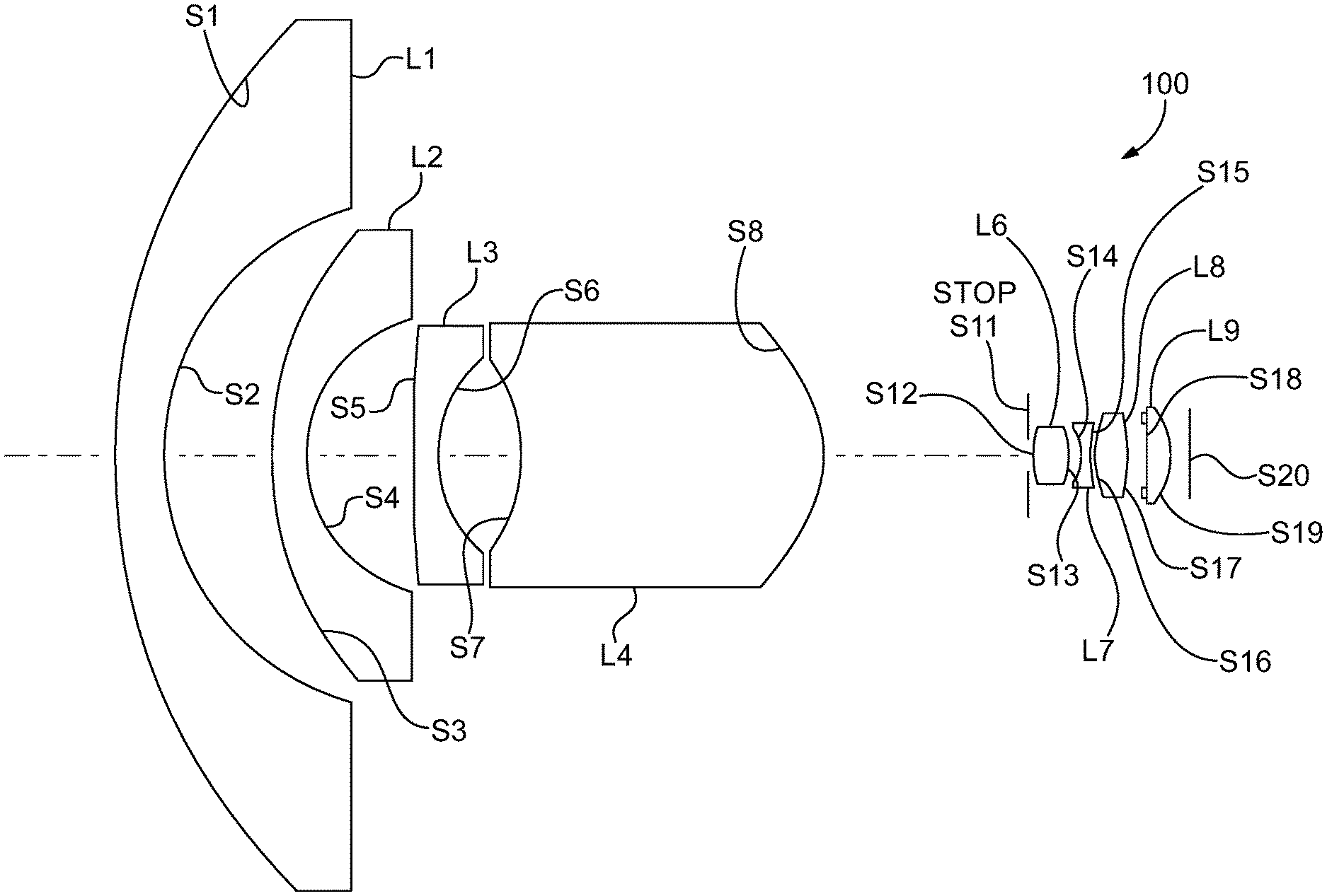
[0010] FIG. 1 schematically illustrates an exemplary eight element lens in accordance with the present invention;
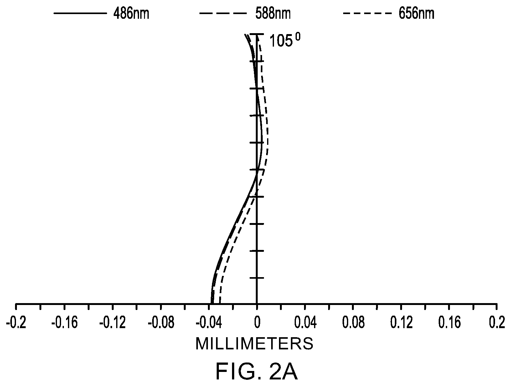
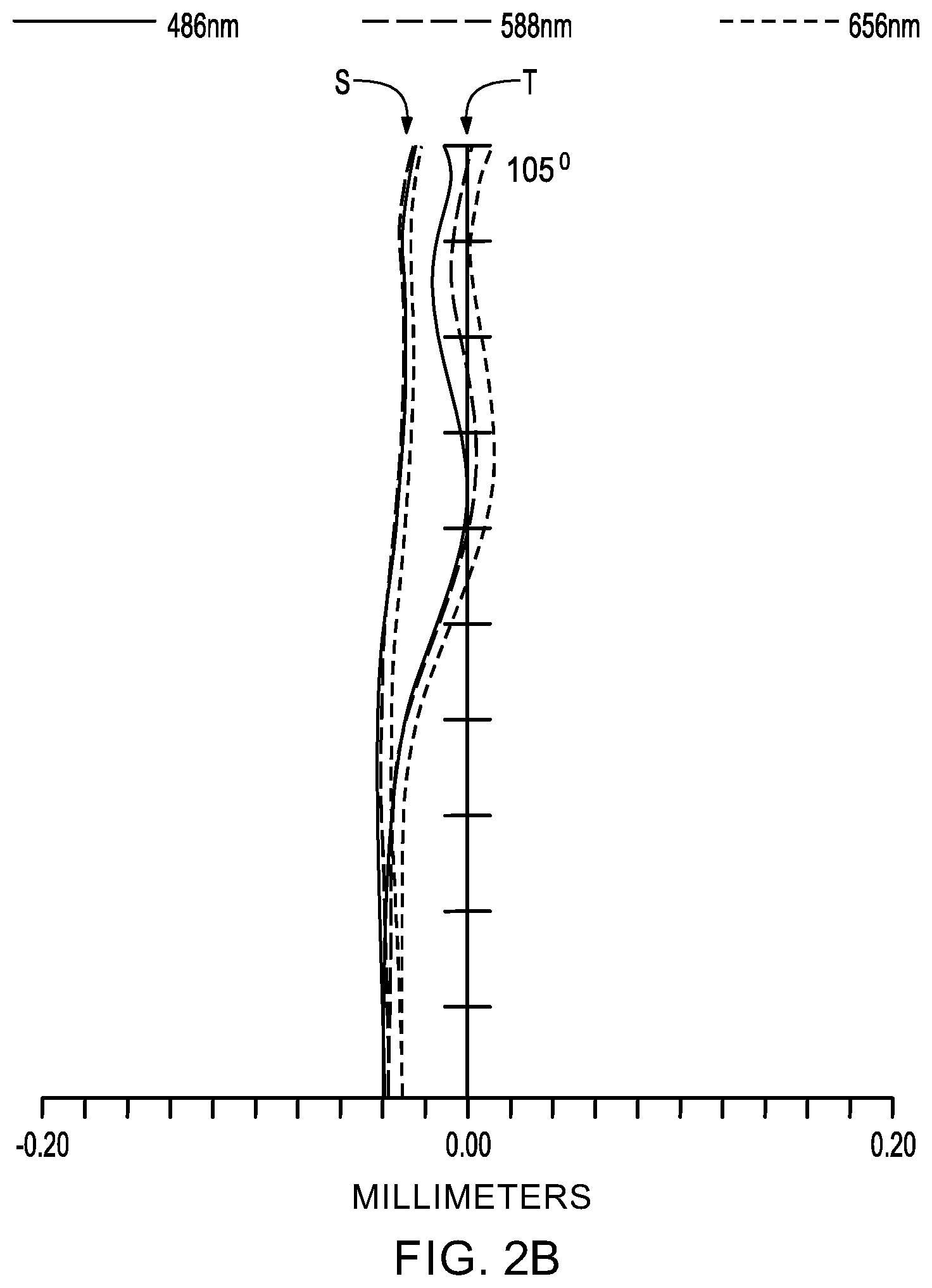
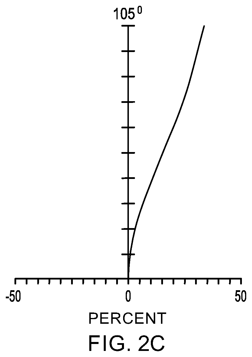
[0011] FIGS. 2A-2C illustrate the calculated longitudinal spherical aberration, field curvature, and f-theta distortion, respectively, of the lens of FIG. 1;
[0012] FIG. 3 schematically illustrates an exemplary nine element lens in accordance with the present invention;
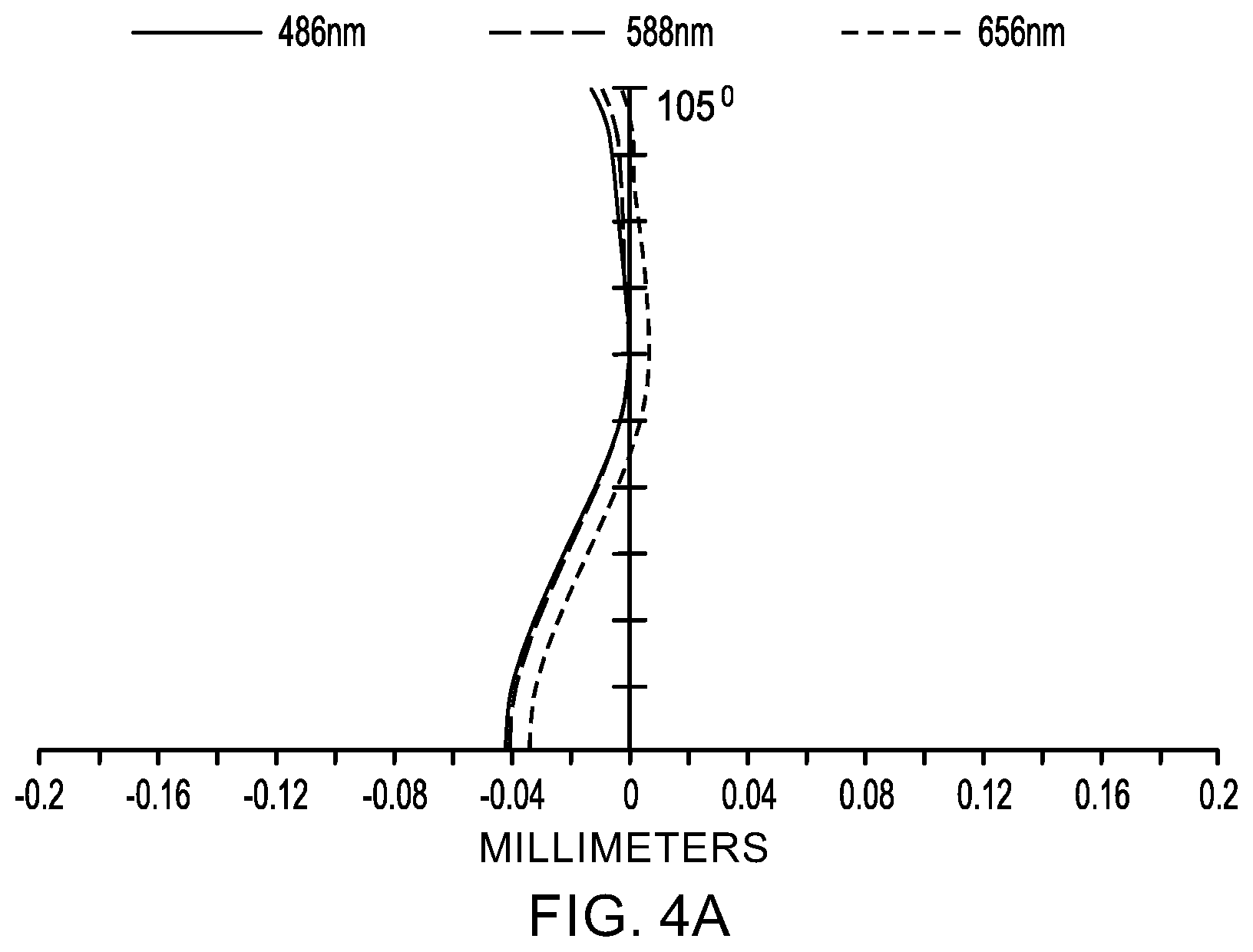
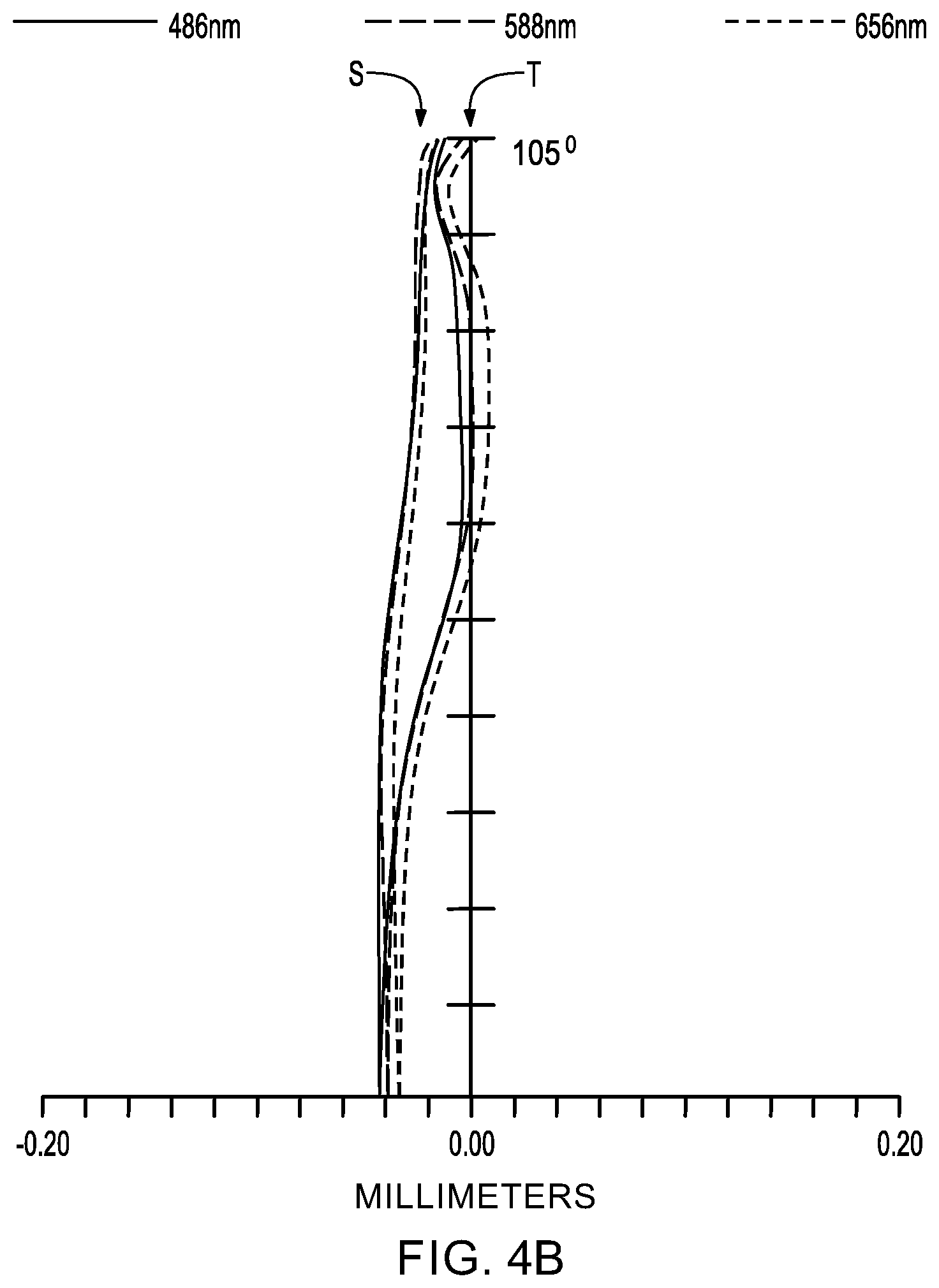
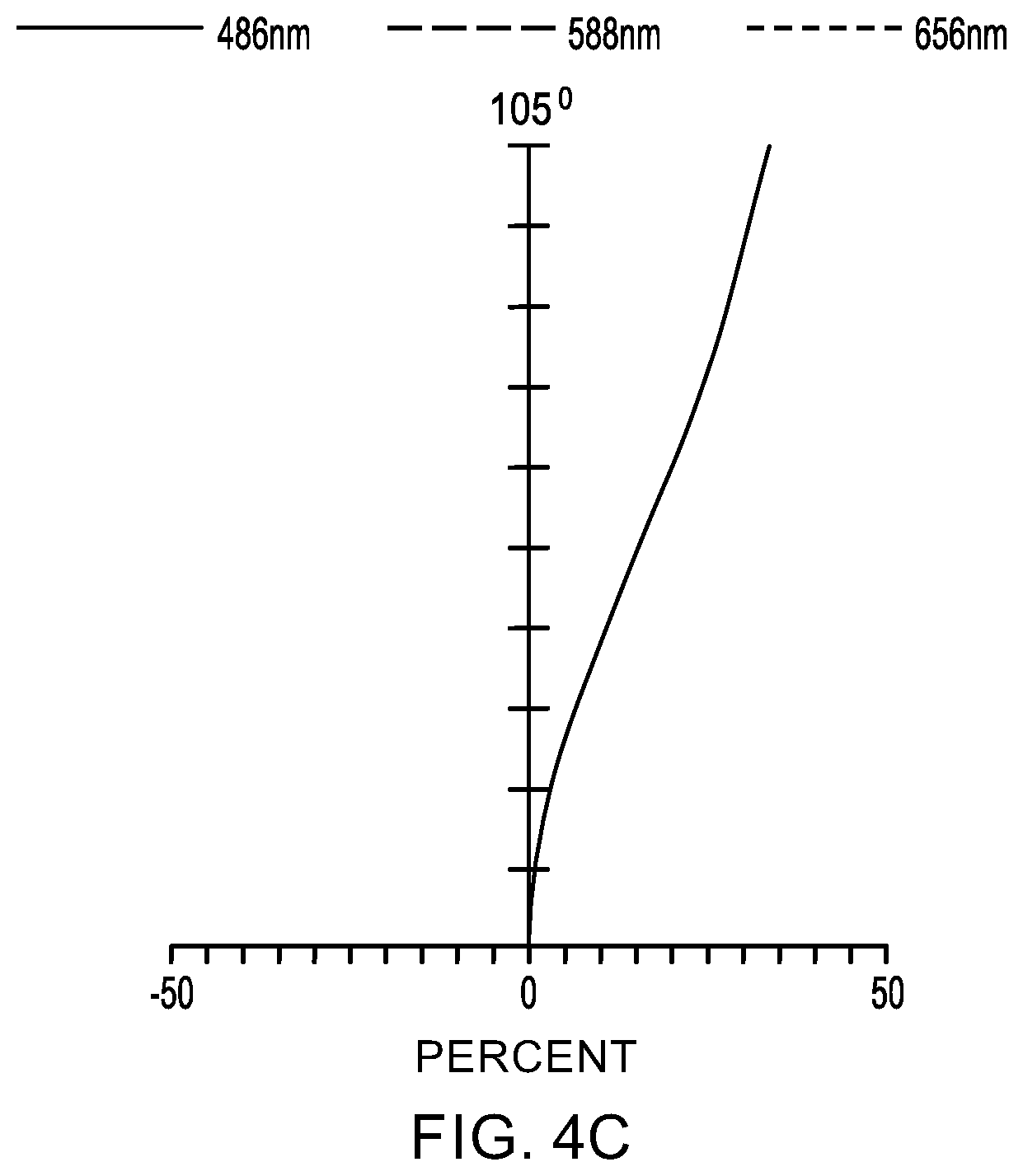
[0013] FIGS. 4A-4C illustrate the calculated longitudinal spherical aberration, field curvature, and f-theta distortion, respectively of the lens of FIG. 3;
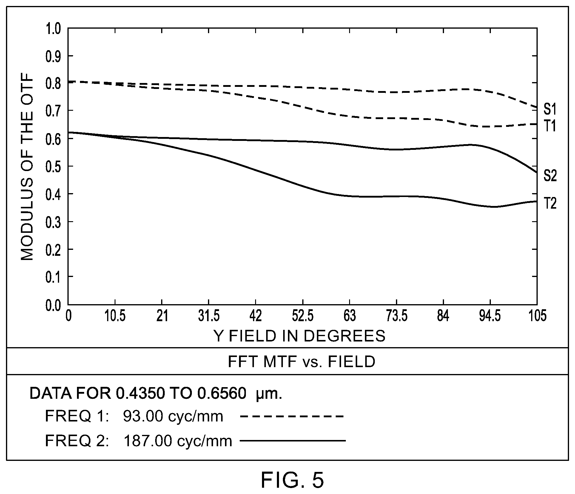
[0014] FIG. 5 illustrates the calculated modulation transfer function versus field for the lens of FIG. 3;
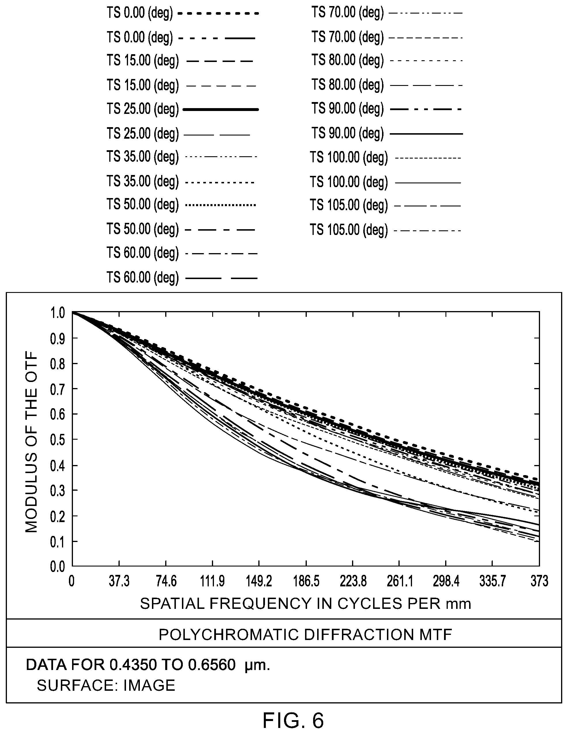
[0015] FIG. 6 illustrates the calculated polychromatic diffraction modulation transfer function versus spatial frequency for the lens of FIG. 3;
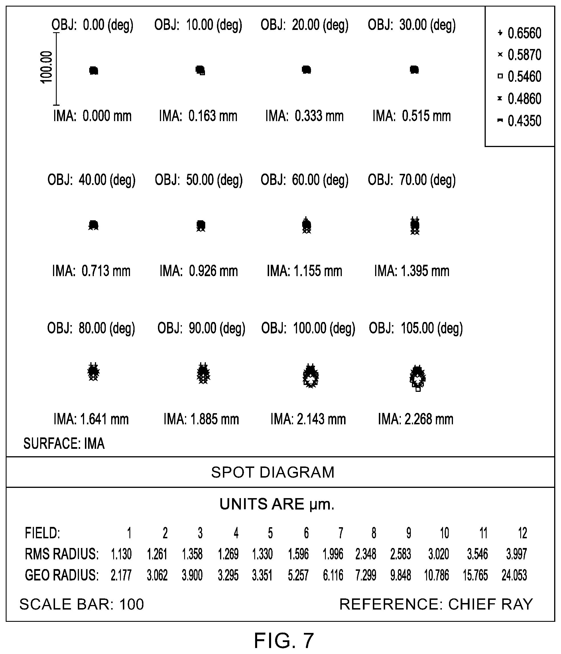
[0016] FIG. 7 illustrates calculated spot diagrams for the lens of FIG. 3;
[0017] FIG. 8 illustrates the calculated polychromatic diffraction through focus modulation transfer function versus focus shift for the lens of FIG. 3;
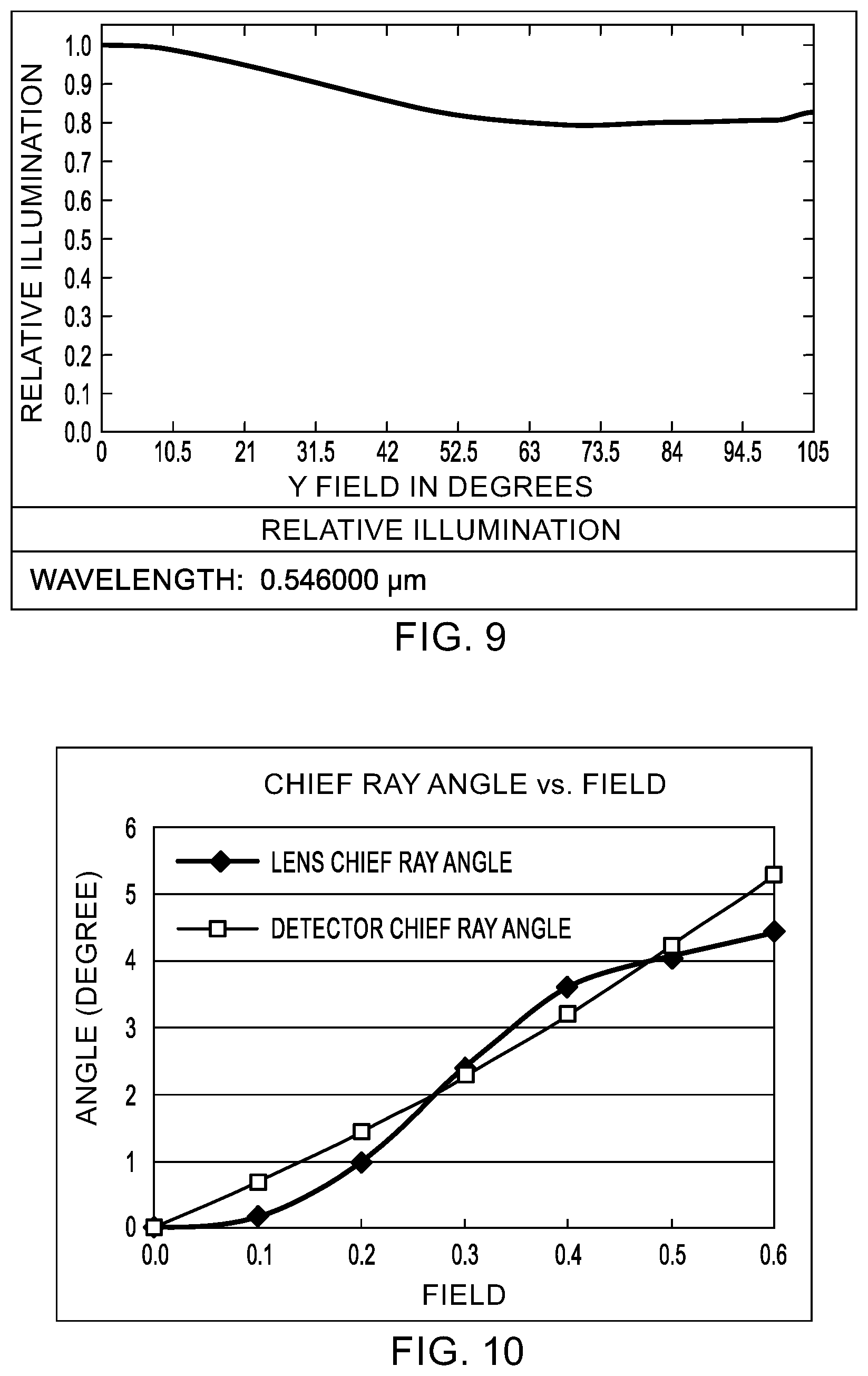
[0018] FIG. 9 illustrates the calculated relative illumination of the image plane versus field for the lens of FIG. 3;
[0019] FIG. 10 illustrates the calculated lens chief ray angle versus field for the lens of FIG. 3 along with the target chief ray angles for an exemplary image sensor (detector); and
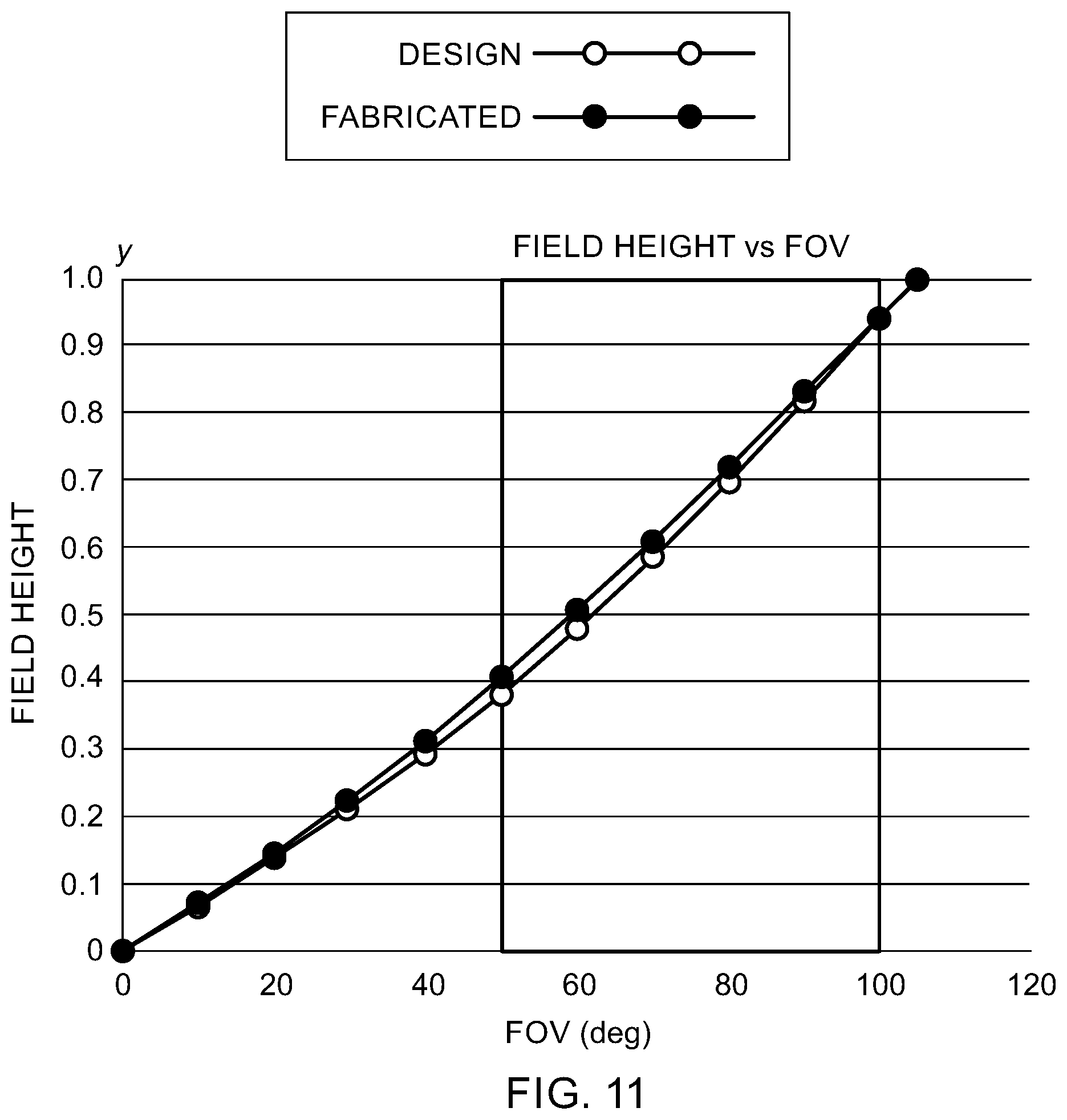
[0020] FIG. 11 illustrates field height versus field of view for the lens of FIG. 3 as designed and fabricated.
DETAILED DESCRIPTION OF THE INVENTION
[0021] Referring now to the figures, wherein like elements are numbered alike throughout, FIGS. 1 and 3 schematically illustrate configurations of exemplary wide angle lenses 100, 200 optimized for performance towards the outer half of the field-of-view in accordance with the present invention. The lenses 100, 200 may have a wide field-of-view of 210.degree. (.+-.105.degree. on either side of the optical axis), and may be optimized for optical performance within a region of interest of the field-of-view. Specifically, with the goal of imaging objects disposed in the periphery of the field-of-view, the region of interest may comprise an annular cone beginning at 50.degree. from the optical axis and extending to 100.degree. from the optical axis. Optical performance outside of the region of interest, e.g., a cone between 0.degree. and 50.degree. field-of-view, may be relaxed and have inferior optical performance to that found in the region of interest. For example, the spherical aberration of the lenses 100, 200 may be well corrected for 50.degree. and above as compared to 50.degree. and below. In addition, by relaxing the requirements for optical performance outside of the region of interest, Applicant has been able to achieve designs in which all optical surfaces are spherical, avoiding the manufacturing complexities and cost associated with aspherical surfaces.
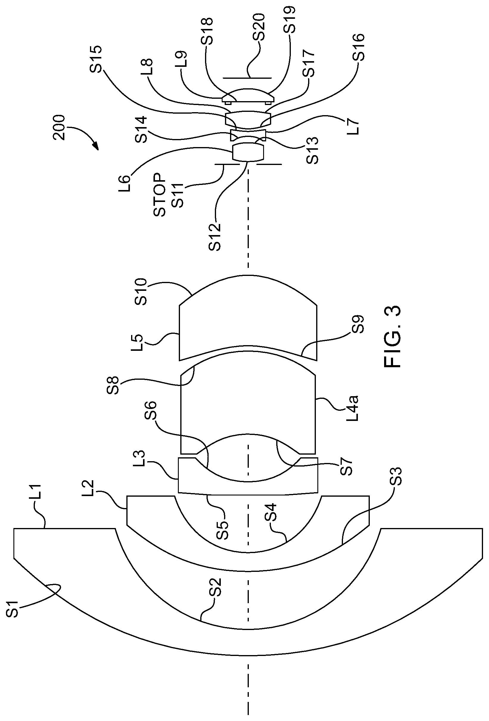
[0022] Turning to the configuration of lens 100 of FIG. 1 more particularly, the lens 100 may include a first group of four optical elements L1-L4 disposed on the object side of an aperture stop S11 and may include a second group of four optical elements L6-L9 disposed on the image side of the stop S11, with first-order design properties shown in Table 1. The first two lenses, L1, L2, are meniscus-type lenses having surfaces which are convex to the object side, and introduce negative power to decrease entering ray angles to be more parallel to the optical axis. Optionally, lens L4 of the lens 100 of FIG. 1 may be replaced by two lens elements L4a, L5, with all other lenses L1-L3 and L6-L9 remaining the same, as shown in Table 2 and FIG. 3. The optical glasses provided in Tables 1, 2 refer to glasses from Schott North America, Inc, Elmsford, N.Y., USA, and Nd refers to a wavelength of 587.6 nm. The cyclic olefin copolymer "COC" in Tables 1, 2 may be APEL.TM. Cyclo olefin copolymer APL5014CL (Mitsui Chemicals, Inc., Tokyo, Japan).
TABLE-US-00001 TABLE 1 Eight element design Surface R(mm) d(mm) Nd Vd Note Material S1 29.2909 2.3865 1.806 41.00 L1 N-LASF43 S2 12.2744 5.1328 S3 16.1766 1.6535 1.804 46.6 L2 N-LASF44 S4 6.7924 5.1229 S5 82.6538 1.2012 1.64 60.2 L3 N-LAK21 S6 6.2407 4.1457 S7 -6.7625 15.1741 1.544 56.00 L4 COC S8 -6.0836 10.2985 S11 infinity 0.2611 Stop S12 4.4027 1.6888 1.589 61.3 L6 P-SK58A S13 -3.8501 0.7362 S14 -2.6508 0.3804 1.642 22.5 L7 PC S15 4.0385 0.2402 S16 6.1489 1.5593 1.544 56.00 L8 COC S17 -3.6755 0.7822 S18 -37.2014 1.1781 1.544 56.00 L9 COC S19 -3.3096 0.9428 S20 Infinity -- Image
TABLE-US-00002 TABLE 2 Nine element design Surface R(mm) d(mm) Nd Vd Note Material S1 29.2909 2.3865 1.806 41.00 L1 N-LASF43 S2 12.2744 5.1328 S3 16.1766 1.6535 1.804 46.6 L2 N-LASF44 S4 6.7924 5.1229 S5 82.6538 1.2012 1.64 60.2 L3 N-LAK21 S6 6.2407 4.2648 S7 -5.5241 7.4709 1.544 56.00 L4a COC S8 -8.6995 0.3750 S9 -12.5165 6.3058 1.544 56.00 L5 COC S10 -6.2516 9.8205 S11 infinity 0.2426 Stop S12 4.4027 1.6888 1.589 61.3 L6 P-SK58A S13 -3.8501 0.7362 S14 -2.6508 0.3804 1.642 22.5 L7 PC S15 4.0385 0.2402 S16 6.1489 1.5593 1.544 56.00 L8 COC S17 -3.6755 0.7822 S18 -37.2014 1.1781 1.544 56.00 L9 COC S19 -3.3096 0.9428 S20 Infinity -- Image
[0023] Regarding the optical performance, since designs in accordance with the present invention are focused on performance in a region of interest comprising an annular cone extending to the edge of the field-of-view, performance near the optical axis may be reduced. For example, in terms of classically defined aberrations, as illustrated in FIGS. 2A, 4A the longitudinal spherical aberration may be well corrected in the region of interest between 50.degree. and 100.degree., while a relatively large spherical aberration on-axis of 40 .mu.m may be tolerated. In particular, the longitudinal spherical aberration may be so well corrected in the region of interest that the value in the region of interest may be less than one quarter of that present on-axis. Similarly, field curvature, especially for tangential rays, may be minimized in the region of interest while being comparatively larger on-axis, FIGS. 2B, 4B. Like the spherical aberration, the field curvature for tangential rays in the region of interest may be less than one quarter of that present on-axis. While not intending to be bound by any particular theory, it is believed that third order field curvature may be corrected by introducing compensating higher order field curvature via lens element L5 of lens 200, and via lens elements L7, L8. F-theta distortion, unlike longitudinal spherical aberration and field curvature, may increase with field height without correction, but may be constrained to be less than 34% at full field, FIGS. 2C, 4C.
[0024] Specified in terms of modulation transfer function (MTF) rather than third order aberrations, exemplary target values for the MTF in the region of interest are provided in Table 3, which may be selected with regard to the detector to be used at the image plane. Specifically, the size and spacing of the pixels on the detector can establish the Nyquist frequency for the MTF design targets. For example, in the case of an exemplary detector having a pixel size of 1.34 .mu.m.times.1.34 .mu.m (OV16825 16-megapixel CameraChip.TM. sensor, OmniVision Technologies, Inc., Santa Clara, Calif., USA), one quarter of the Nyquist frequency would correspond to 93 lp/mm, and one half of the Nyquist frequency would correspond to 187 lp/mm. The calculated performance for the design of the lens 200 of FIG. 3 with regard to MTF is illustrated in FIGS. 5, 6, and 8, as well as Table 4. Performance of the design of the lens 200 of FIG. 3 in terms of spot diagrams as illustrated in FIG. 7. In addition, the ability to properly illuminate the detector at the image plane is illustrated in terms of relative illumination in FIG. 9, which illustrates that 80% relative illumination is maintained out to 105.degree.. This result is consistent with proper control of the chief ray angles as illustrated in FIG. 10, which shows that the lens chief ray angle may be maintained .+-.2.degree. from the target detector chief ray angle over 60% of field.
[0025] In addition, designs in accordance with the present invention, including that of lens 200, may seek to optimize mapping of the angular field-of-view onto the detector in a manner that is both linear in the region of interest (e.g., annular cone beginning at 50.degree. from the optical axis and extending to 100.degree. from the optical axis) and maximizes the number of pixels on the image sensor S20 onto which the region of interest of the field-of-view is mapped. In particular, FIG. 11 illustrates that the field of view over the region of interest is substantially linearly mapped onto the field at the image sensor S20, with 50.degree. field of view mapping to h=0.4 relative field height and 100.degree. mapping to H=0.95 relative field height, for a ratio of H/h=2.375 on the image detector. The number of pixels covered on the image sensor may also be optimized in this region, with roughly 970 pixels disposed within the field-of-view between 50.degree. and 100.degree. for the exemplary sensor model OV16825 mentioned above, where the number of pixels is counted along a line taken along one of the two orthogonal directions on which the 1.34 .mu.m.times.1.34 .mu.m grid of pixels of the image sensor is organized. For this pixel size, 970 pixels corresponds to 1.3 mm (970.times.1.34 .mu.m). Thus, the annular field-of-view between 50.degree. and 100.degree. maps to a linear distance of about 1.3 mm taken along one of the two orthogonal axes of the sensor grid.
[0026] Specified more generally, the region of interest may extend between a first angle and a second angle from the optical axis in object space, where the ratio of the second angle to the first angle is R and may be in the range of R=1.67:1 to 2.5:1. The lens may be configured and constructed such that a ray of the second angle in object space intersects the lens image plane at a distance, H, from the optical axis and a ray of the first angle in object space intersects the lens image plane at a distance, h, from the optical axis such that H/h>R, or preferably H/h.gtoreq.1.1.times.R, or more preferably H/h.gtoreq.1.5.times.R.
[0027] Another metric for specifying the angular mapping of the region of interest onto the image plane may be provided with respect to the full field-of-view, FOV, and half field-of-view, FOV.sub.1/2, that is FOV/FOV.sub.1/2=2. The lens may be constructed and arranged such that a ratio of a diameter (D.sub.1) at the image plane of an image circle of the full field-of-view versus the diameter (D.sub.1/2) of an image circle of the central half field-of-view is D.sub.1/D.sub.1/2>2. Also D.sub.1/D.sub.1/2.gtoreq.2.2, or preferably D.sub.1/D.sub.1/2.gtoreq.2.5, or more preferably D.sub.1/D.sub.1/2.gtoreq.3. For example, seventy-five percent or more of pixel sensor elements of the image sensor may be disposed in the image region corresponding to the annular field-of-view between 50.degree. and 100.degree.. Again, the angular mapping of the field of view in the region of interest onto the image plane may be substantially linear.
TABLE-US-00003 TABLE 3 MTF design target values FOV (deg) MTF at 95 lp/mm MTF at 190 lp/mm 50 0.8 0.6 60 0.8 0.6 70 0.75 0.55 80 0.7 0.5 90 0.6 0.4 100 0.5 0.3
TABLE-US-00004 TABLE 4 Nine element design Results Item Specification Notes Image Sensor Resolution 4608 * 3456 (1/2.3 inch) Image Sensor Pixel Size 1.34 .mu.m * 1.34 .mu.m Effective Focal Length 0.93 mm F. No. 2.4 Object Distance 10 cm to infinity View Angle Horizontal -- Image Height = 3.087 mm Vertical 210 deg. Image Height = 2.271 mm Diagonal -- Image Height = 3.859 mm Resolution (MTF) 50 deg 44.9%(T) 59.5%(S) at 187 lp/mm 60 deg 40.8%(T) 58.6%(S) (1/2 Nyquist freq.) 70 deg 39.5%(T) 56.8%(S) 80 deg 39.3%(T) 56.7%(S) 90 deg 37.4%(T) 57.9%(S) 100 deg 36.9%(T) 55.4%(S) 50 deg 73.1%(T) 78.9%(S) at 93 lp/mm 60 deg 70%(T) 78.1%(S) (1/4 Nyquist freq.) 70 deg 68.3%(T) 77.1%(S) 80 deg 67.8%(T) 77.2%(S) 90 deg 67.2%(T) 77.9%(S) 100 deg 64.8%(T) 75.9%(S) F-theta Distortion 33% Relative Illumination 82% at full image height CRA on Sensor <4.44 deg. Total Track Length 54.07 mm Optical Length 54.07 mm Max. Image Circle 4.6 mm
TABLE-US-00005 TABLE 5 Lens Chief Ray Angle (CRA) Image Field CRA (deg.) 0.000 0 0.00 0.389 0.1 0.14 0.778 0.2 0.97 1.167 0.3 2.40 1.556 0.4 3.60 1.945 0.5 4.05 2.271 0.6 4.44
TABLE-US-00006 TABLE 6 Sensor Chief Ray Angle (CRA) Image Field CRA (deg.) 0.000 0 0.00 0.389 0.1 0.69 0.778 0.2 1.43 1.167 0.3 2.27 1.556 0.4 3.20 1.945 0.5 4.22 2.334 0.6 5.27
TABLE-US-00007 TABLE 7 Image Sensor Lens OV16825 (1/2.3'') 210 deg FOV 4608 .times. 3456, 1.34 .mu.m FOV (degree) Real Height Field Pixel 0 0 0 0 10 0.163 0.070 122 20 0.333 0.144 248 30 0.515 0.222 384 40 0.712 0.307 531 50 0.925 0.400 690 60 1.154 0.498 861 70 1.393 0.602 1040 80 1.640 0.708 1224 90 1.894 0.818 1413 100 2.143 0.926 1599 105 2.271 0.981 1694
[0028] These and other advantages of the present invention will be apparent to those skilled in the art from the foregoing specification. Accordingly, it will be recognized by those skilled in the art that changes or modifications may be made to the above-described embodiments without departing from the broad inventive concepts of the invention. It should therefore be understood that this invention is not limited to the particular embodiments described herein, but is intended to include all changes and modifications that are within the scope and spirit of the invention as set forth in the claims. Furthermore, the transitional terms "comprising" and "consisting of" when used in the appended claims define the claim scope with respect to what unrecited additional claim elements or steps, if any, are excluded from the scope of the claims. The term "comprising" is intended to be inclusive or open-ended and does not exclude any additional unrecited element or material. The term "consisting of" excludes any element or material other than those used in connection therewith as specified in the claims.
* * * * *
D00000
D00001
D00002
D00003
D00004
D00005
D00006
D00007
D00008
D00009
D00010
D00011
D00012
D00013
D00014
XML
uspto.report is an independent third-party trademark research tool that is not affiliated, endorsed, or sponsored by the United States Patent and Trademark Office (USPTO) or any other governmental organization. The information provided by uspto.report is based on publicly available data at the time of writing and is intended for informational purposes only.
While we strive to provide accurate and up-to-date information, we do not guarantee the accuracy, completeness, reliability, or suitability of the information displayed on this site. The use of this site is at your own risk. Any reliance you place on such information is therefore strictly at your own risk.
All official trademark data, including owner information, should be verified by visiting the official USPTO website at www.uspto.gov. This site is not intended to replace professional legal advice and should not be used as a substitute for consulting with a legal professional who is knowledgeable about trademark law.