Optical Lens
LAI; Ching-Lung ; et al.
U.S. patent application number 16/685208 was filed with the patent office on 2020-06-18 for optical lens. The applicant listed for this patent is Rays Optics Inc.. Invention is credited to Hsin-Te CHEN, Hung-You CHENG, Ching-Lung LAI, Sheng-Tang LAI.
| Application Number | 20200192066 16/685208 |
| Document ID | / |
| Family ID | 71073565 |
| Filed Date | 2020-06-18 |


View All Diagrams
| United States Patent Application | 20200192066 |
| Kind Code | A1 |
| LAI; Ching-Lung ; et al. | June 18, 2020 |
OPTICAL LENS
Abstract
An optical lens includes a first lens group, a second lens group and an aperture stop. The first lens group includes three lenses with refractive powers. The second lens group has a positive refractive power and includes two lenses with refractive power. The aperture stop is disposed between the first lens group and the second lens group. The optical lens satisfies the conditions of 2 mm<DL<6 mm, LT<15 mm and 0.2<DL/LT<0.38, where DL is a diameter of a lens surface of the second lens group furthest from the first lens group, and LT is a length measured on the optical axis between two outermost lens surfaces of the optical lens.
| Inventors: | LAI; Ching-Lung; (Hukou Township, TW) ; CHENG; Hung-You; (Hukou Township, TW) ; CHEN; Hsin-Te; (Hukou Township, TW) ; LAI; Sheng-Tang; (Hukou Township, TW) | ||||||||||
| Applicant: |
|
||||||||||
|---|---|---|---|---|---|---|---|---|---|---|---|
| Family ID: | 71073565 | ||||||||||
| Appl. No.: | 16/685208 | ||||||||||
| Filed: | November 15, 2019 |
| Current U.S. Class: | 1/1 |
| Current CPC Class: | G02B 13/06 20130101; G02B 13/04 20130101; G02B 9/34 20130101; G02B 13/0045 20130101; G02B 9/60 20130101; G02B 9/62 20130101; G02B 13/006 20130101 |
| International Class: | G02B 13/00 20060101 G02B013/00; G02B 9/60 20060101 G02B009/60; G02B 9/62 20060101 G02B009/62 |
Foreign Application Data
| Date | Code | Application Number |
|---|---|---|
| Dec 14, 2018 | TW | 107145161 |
Claims
1. An optical lens, comprising: a first lens group comprising three lenses with refractive powers, and the three lenses comprising a spherical lens and an aspheric lens; a second lens group having a positive refractive power and comprising two lenses with refractive powers, and the two lenses comprising an aspheric lens; and an aperture stop disposed between the first lens group and the second lens group, wherein a total number of lenses in the optical lens is less than 9, and the optical lens satisfies the conditions: 2 mm<DL<6 mm; LT<15 mm; and 0.2<DL/LT<0.38, where DL is a diameter of a lens surface of the second lens group furthest from the first lens group, and LT is a length measured on the optical axis between two outermost lens surfaces of the optical lens.
2. The optical lens as claimed in claim 1, wherein an F-number of the optical lens is larger than or equal to 1.8.
3. The optical lens as claimed in claim 1, wherein a full field of view of the optical lens is greater than 190 degrees and smaller than 230 degrees.
4. The optical lens as claimed in claim 1, wherein the optical lens satisfies one of the following conditions: (1) the optical lens comprises three lenses with an Abbe number of greater than 50; (2) the optical lens comprises three lenses with an Abbe number of greater than 55; (3) the optical lens comprises three plastic lenses with an Abbe number of greater than 50.
5. The optical lens as claimed in claim 1, wherein the optical lens satisfies one of the following conditions: (1) the optical lens comprises a cemented lens having a lens with an Abbe number of greater than 50; (2) the optical lens comprises a cemented lens having an aspheric joint surface.
6. The optical lens as claimed in claim 1, wherein the optical lens satisfies one of the following conditions: (1) the optical lens comprises a doublet lens; (2) the optical lens comprises a triplet lens; (3) a lens furthest from an image plane of the optical lens is made from glass.
7. The optical lens as claimed in claim 1, wherein the length LT is smaller than 15 mm.
8. The optical lens as claimed in claim 1, wherein a total track length of the optical lens measured between a lens surface furthest from an image plane and the image plane is smaller than 18 mm.
9. The optical lens as claimed in claim 1, wherein the optical lens satisfies one of the following conditions: (1) the optical lens comprises, in order from a magnified side to a minified side, a meniscus lens, an aspheric lens, an aspheric lens, a bi-convex lens, an aspheric lens and an aspheric lens; (2) the optical lens comprises, in order from a magnified side to a minified side, a meniscus lens, an aspheric lens, a bi-convex lens, an aspheric lens, an aspheric lens and an aspheric lens; (3) the optical lens comprises, in order from a magnified side to a minified side, a meniscus lens, an aspheric lens, an aspheric lens, an aspheric lens and an aspheric lens; (4) the optical lens comprises, in order from a magnified side to a minified side, a meniscus lens, an aspheric lens, an aspheric lens, an aspheric lens, an aspheric lens and an aspheric lens; (5) the optical lens comprises, in order from a magnified side to a minified side, a meniscus lens, an aspheric lens, an aspheric lens, a bi-convex lens and an aspheric lens; (6) the optical lens comprises, in order from a magnified side to a minified side, a meniscus lens, an aspheric lens, a bi-convex lens, an aspheric lens and an aspheric lens.
10. The optical lens as claimed in claim 1, wherein the optical lens satisfies one of the following conditions: (1) the optical lens has six lenses with refractive powers of negative, negative, negative, positive, negative and positive; (2) the optical lens has six lenses with refractive powers of negative, negative, positive, positive, negative and positive; (3) the optical lens has five lenses with refractive powers of negative, negative, positive, negative and positive. (4) the optical lens has five lenses with refractive powers of negative, negative, positive, positive and positive.
11. An optical lens, comprising: a first lens, a second lens, a third lens, a fourth lens and a fifth lens arranged in order from a magnified side to a minified side, the second lens and the fifth lens being aspheric lenses, a total number of lenses in the optical lens being less than 9, and the optical lens satisfying the conditions: 5 mm<EFL<1.5 mm; D1<13.3 mm; LT<15 mm; and 0.05<EFL/LT<0.1, where EFL is an effective focal length of the optical lens, D1 is a diameter of a lens surface of the first lens furthest from the second lens, and LT is a length measured on the optical axis between two outermost lens surfaces of the optical lens.
12. The optical lens as claimed in claim 11, wherein an F-number of the optical lens is larger than or equal to 1.8.
13. The optical lens as claimed in claim 11, wherein a full field of view of the optical lens is greater than 190 degrees and smaller than 230 degrees.
14. The optical lens as claimed in claim 11, wherein the optical lens satisfies one of the following conditions: (1) the optical lens comprises three lenses with an Abbe number of greater than 50; (2) the optical lens comprises three lenses with an Abbe number of greater than 55; (3) the optical lens comprises three plastic lenses with an Abbe number of greater than 50.
15. The optical lens as claimed in claim 11, wherein the optical lens satisfies one of the following conditions: (1) the optical lens comprises a cemented lens having a lens with an Abbe number of greater than 50; (2) the optical lens comprises a cemented lens having an aspheric joint surface.
16. The optical lens as claimed in claim 11, wherein the optical lens satisfies one of the following conditions: (1) the optical lens comprises a doublet lens; (2) the optical lens comprises a triplet lens; (3) a lens furthest from an image plane of the optical lens is made from glass.
17. The optical lens as claimed in claim 11, wherein the length LT is smaller than 15 mm.
18. The optical lens as claimed in claim 11, wherein a total track length of the optical lens measured between a lens surface furthest from an image plane and the image plane is smaller than 18 mm.
19. The optical lens as claimed in claim 11, wherein the optical lens satisfies one of the following conditions: (1) the optical lens comprises, in order from the magnified side to the minified side, a meniscus lens, an aspheric lens, an aspheric lens, a bi-convex lens, an aspheric lens and an aspheric lens; (2) the optical lens comprises, in order from the magnified side to the minified side, a meniscus lens, an aspheric lens, a bi-convex lens, an aspheric lens, an aspheric lens and an aspheric lens; (3) the optical lens comprises, in order from the magnified side to the minified side, a meniscus lens, an aspheric lens, an aspheric lens, an aspheric lens and an aspheric lens; (4) the optical lens comprises, in order from the magnified side to the minified side, a meniscus lens, an aspheric lens, an aspheric lens, an aspheric lens, an aspheric lens and an aspheric lens; (5) the optical lens comprises, in order from the magnified side to the minified side, a meniscus lens, an aspheric lens, an aspheric lens, a bi-convex lens and an aspheric lens; (6) the optical lens comprises, in order from the magnified side to the minified side, a meniscus lens, an aspheric lens, a bi-convex lens, an aspheric lens and an aspheric lens.
20. The optical lens as claimed in claim 11, wherein the optical lens satisfies one of the following conditions: (1) the optical lens has six lenses with refractive powers of negative, negative, negative, positive, negative and positive; (2) the optical lens has six lenses with refractive powers of negative, negative, positive, positive, negative and positive; (3) the optical lens has five lenses with refractive powers of negative, negative, positive, negative and positive. (4) the optical lens has five lenses with refractive powers of negative, negative, positive, positive and positive.
Description
BACKGROUND OF THE INVENTION
a. Field of the Invention
[0001] The invention relates generally to an optical system, and more particularly to an optical lens.
b. Description of the Related Art
[0002] Recent advances in technology have led to the development of various types of optical lenses. For example, an image pick-up lens used in a surveillance camera, an in-vehicle camera or an action camera is a commonly used optical lens. Nowadays, there is a growing need for an optical lens to be miniaturized and have high optical performance. To meet these requirements, the optical lens needs to have low fabrication costs, high resolution, large effective aperture, wide viewing angles, low thermal shift and reduced occupied space. Therefore, it is desirable to provide an optical lens that may achieve miniaturization, wider viewing angles, lower thermal shift, reduced fabrication costs, and better imaging quality.
BRIEF SUMMARY OF THE INVENTION
[0003] According to one aspect of the present disclosure, an optical lens includes a first lens group, a second lens group and an aperture stop. The first lens group includes three lenses with refractive powers, and the three lenses include a spherical lens and an aspheric lens. The second lens group has a positive refractive power and includes two lenses with refractive power, and the two lenses include an aspheric lens. The aperture stop is disposed between the first lens group and the second lens group, where a total number of lenses in the optical lens is less than 9, and the optical lens satisfies the conditions of 2 mm<DL<6 mm, LT<15 mm and 0.2<DL/LT<0.38, where DL is a diameter of a lens surface of the second lens group furthest from the first lens group, and LT is a length measured on the optical axis between two outermost lens surfaces of the optical lens.
[0004] According to another aspect of the present disclosure, an optical lens includes a first lens, a second lens, a third lens, a fourth lens and a fifth lens arranged in order from a magnified side to a minified side, the second lens and the fifth lens are aspheric lenses, and a total number of lenses in the optical lens is less than 9. The optical lens satisfies the conditions of 0.5 mm<EFL<1.5 mm, D1<13.3 mm, LT<15 mm and 0.05<EFL/LT<0.1, where EFL is an effective focal length of the optical lens, D1 is a diameter of a lens surface of the first lens furthest from the second lens, and LT is a length measured on the optical axis between two outermost lens surfaces of the optical lens.
[0005] According to the above embodiments, the optical lens may achieve high optical performance, low thermal shift, wide viewing angles, low fabrication costs and good imaging quality. Further, a total number of lenses can be reduced to 5-8, and a total track length can be decreased to be smaller than 18 mm. Therefore, an optical lens having large effective aperture, high resolution, wide viewing angles, low thermal shift, reduced occupied space, low fabrication costs and good imaging quality can be provided.
[0006] Other objectives, features and advantages of the invention will be further understood from the further technological features disclosed by the embodiments of the invention wherein there are shown and described preferred embodiments of this invention, simply by way of illustration of modes best suited to carry out the invention.
BRIEF DESCRIPTION OF THE DRAWINGS
[0007] FIG. 1 shows a cross-sectional illustration of an optical lens according to an embodiment of the invention, and FIG. 2 illustrates spherical aberration, field curvature and distortion plots of the optical lens shown in FIG. 1.
[0008] FIG. 3 shows a cross-sectional illustration of another optical lens according to an embodiment of the invention, and FIG. 4 illustrates spherical aberration, field curvature and distortion plots of the optical lens shown in FIG. 3.
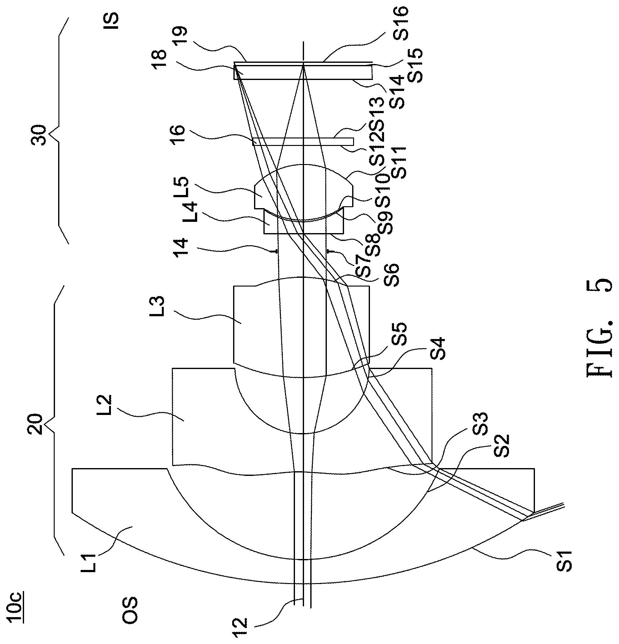
[0009] FIG. 5 shows a cross-sectional illustration of another optical lens according to an embodiment of the invention, and FIG. 6 illustrates spherical aberration, field curvature and distortion plots of the optical lens shown in FIG. 5.
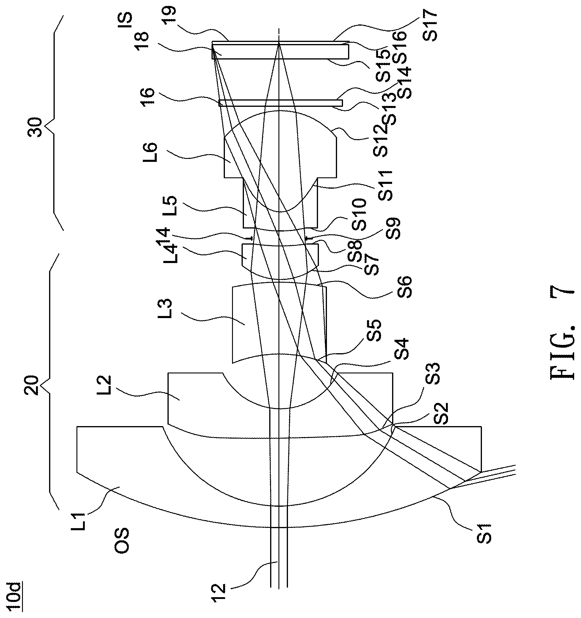
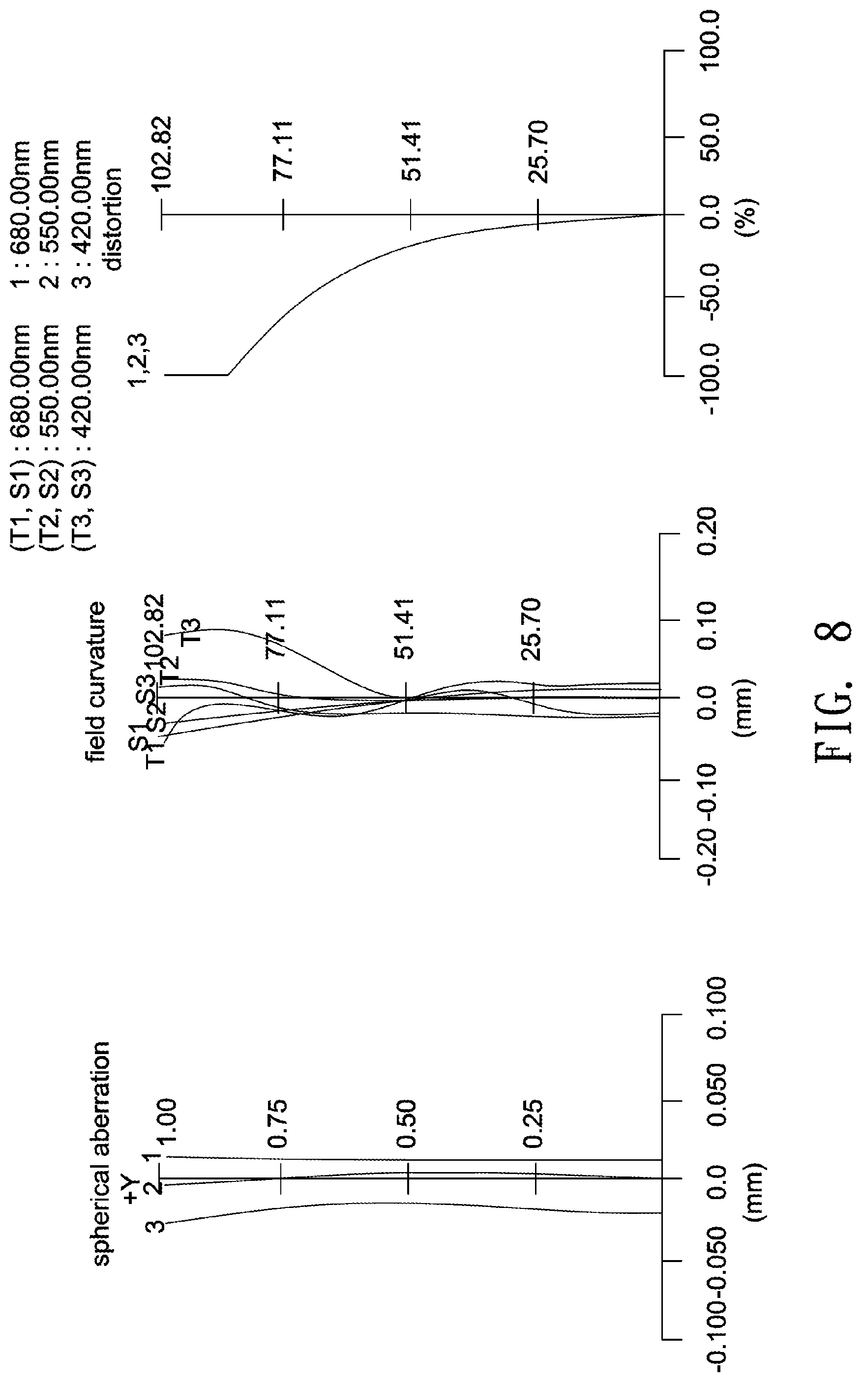
[0010] FIG. 7 shows a cross-sectional illustration of another optical lens according to an embodiment of the invention, and FIG. 8 illustrates spherical aberration, field curvature and distortion plots of the optical lens shown in FIG. 7.
[0011] FIG. 9 shows a cross-sectional illustration of another optical lens according to an embodiment of the invention, and FIG. 10 illustrates spherical aberration, field curvature and distortion plots of the optical lens shown in FIG. 9.
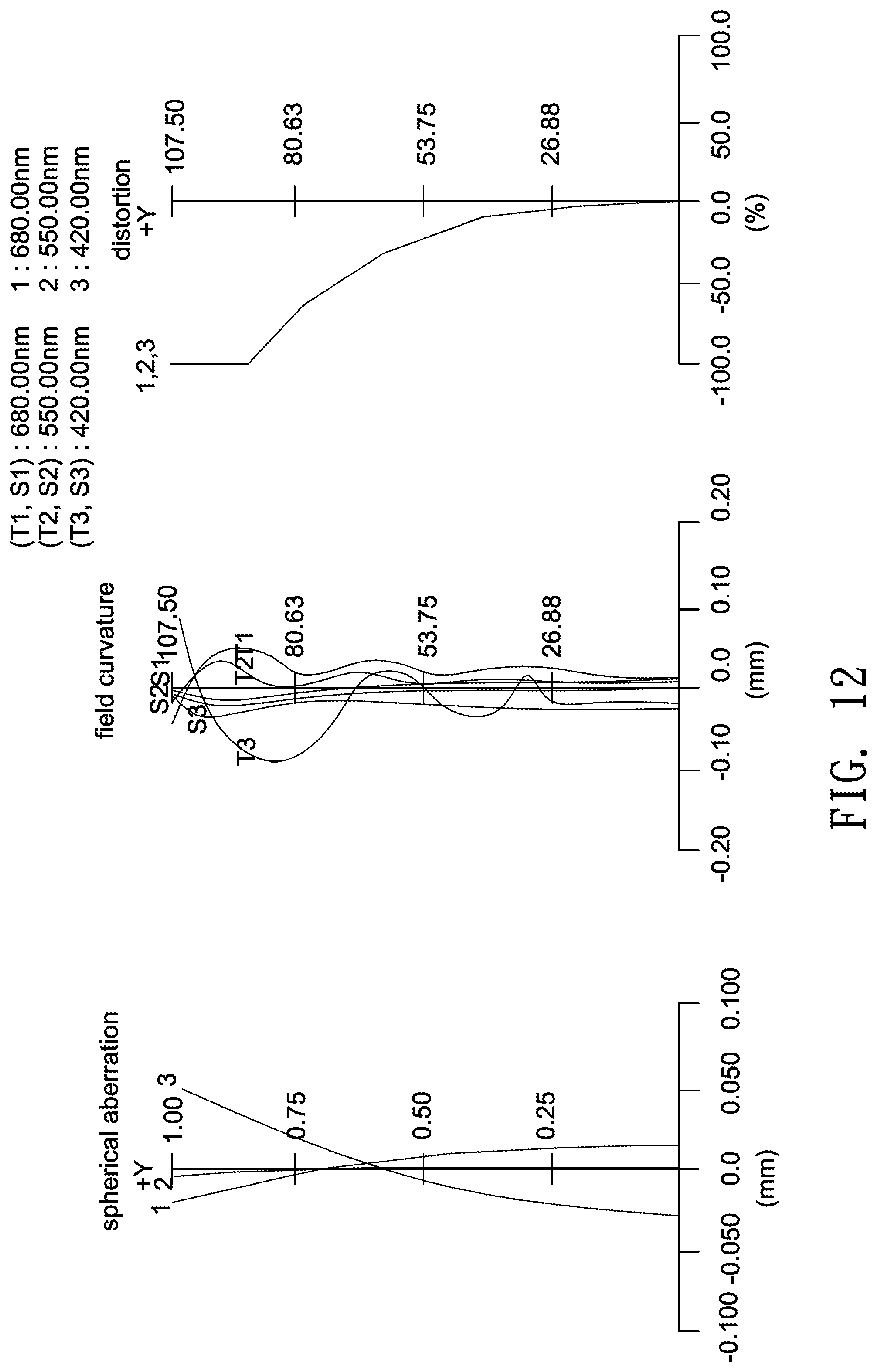
[0012] FIG. 11 shows a cross-sectional illustration of another optical lens according to an embodiment of the invention, and FIG. 12 illustrates spherical aberration, field curvature and distortion plots of the optical lens shown in FIG. 11.
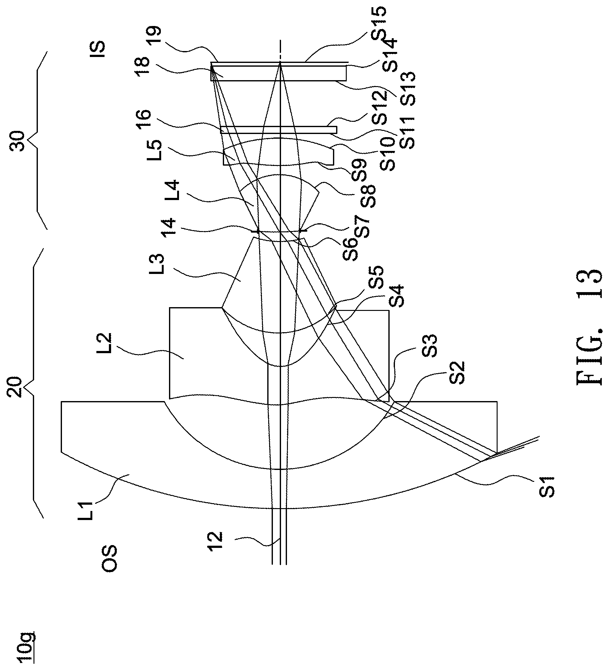
[0013] FIG. 13 shows a cross-sectional illustration of another optical lens according to an embodiment of the invention, and FIG. 14 illustrates spherical aberration, field curvature and distortion plots of the optical lens shown in FIG. 13.
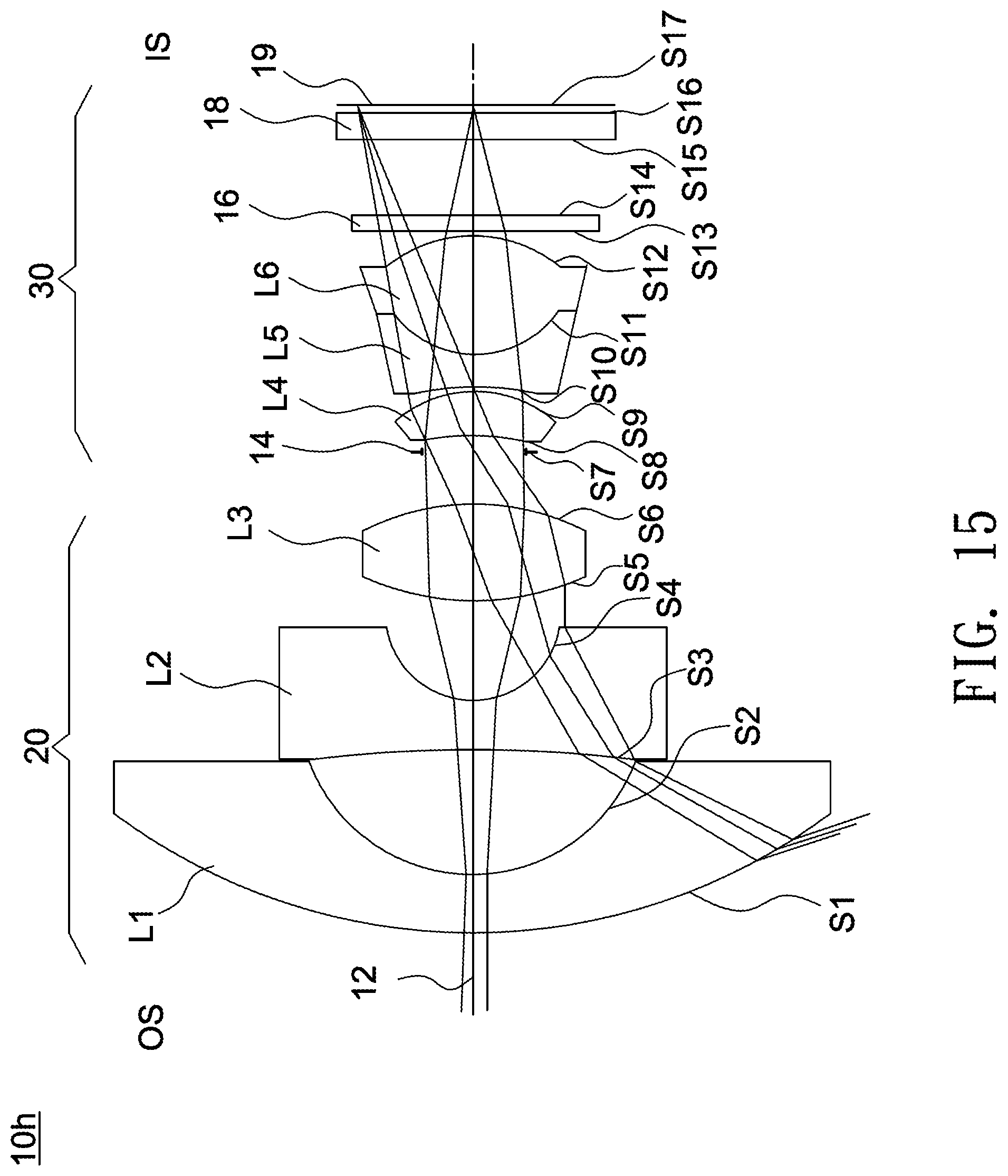
[0014] FIG. 15 shows a cross-sectional illustration of another optical lens according to an embodiment of the invention, and FIG. 16 illustrates spherical aberration, field curvature and distortion plots of the optical lens shown in FIG. 15.
[0015] FIG. 17 shows a cross-sectional illustration of another optical lens according to an embodiment of the invention, and FIG. 18 illustrates spherical aberration, field curvature and distortion plots of the optical lens shown in FIG. 17.
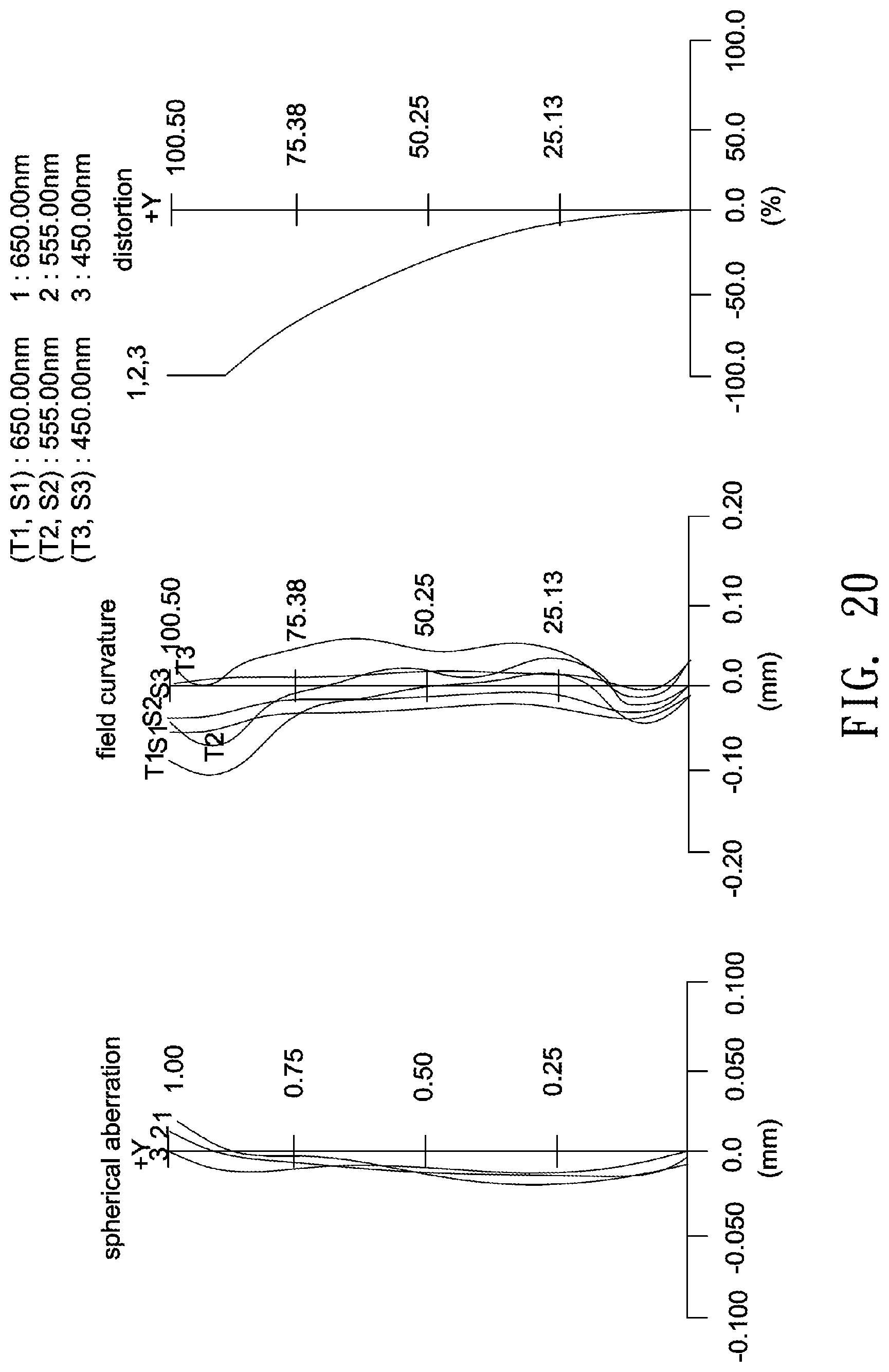
[0016] FIG. 19 shows a cross-sectional illustration of another optical lens according to an embodiment of the invention, and FIG. 20 illustrates spherical aberration, field curvature and distortion plots of the optical lens shown in FIG. 19.
DETAILED DESCRIPTION OF THE INVENTION
[0017] In the following detailed description of the preferred embodiments, directional terminology, such as "top," "bottom," "front," "back," etc., is used with reference to the orientation of the Figure(s) being described. The components of the invention can be positioned in a number of different orientations. As such, the directional terminology is used for purposes of illustration and is in no way limiting. Further, "First," "Second," etc, as used herein, are used as labels for nouns that they precede, and do not imply any type of ordering (e.g., spatial, temporal, logical, etc.). The following embodiments of a zoom lens may be applied to any system or environment according to actual demands.
[0018] The term "optical element" refers to an element made from at least in part a material that may refract, reflect, diffract, diffuse or filter at least a portion of the light passing through it. The material may include plastic or glass, and the optical element may be, for example, a lens, a prism or an aperture stop.
[0019] In an image-pickup system, a magnified side may refer to one side of an optical path of an optical lens comparatively near a subject to be picked-up, and a minified side may refer to other side of the optical path comparatively near a photosensor.
[0020] A certain region of an object side surface (or an image side surface) of a lens may be convex or concave. Herein, a convex or concave region is more outwardly convex or inwardly concave in the direction of an optical axis as compared with other neighboring regions of the object/image side surface.
[0021] FIG. 1 shows a cross-sectional illustration of an optical lens according to an embodiment of the invention. As shown in FIG. 1, in this embodiment, the optical lens 10a has a lens barrel (not shown), and inside the lens barrel a first lens L1, a second lens L2, a third lens L3, a fourth lens L4, an aperture stop 14, a fifth lens L5 and a sixth lens L6 are arranged in order from a first side (magnified side OS) to a second side (minified side IS). The first lens L1, the second lens L2, the third lens L3 and the fourth lens L4 form a first lens group 20 (such as a front lens group) with a negative refractive power, and the fifth lens L5 and the sixth lens L6 form a second lens group 30 (such as a rear lens group) with a positive refractive power.
[0022] Further, the minified side IS may be disposed with an IR (infrared) filter 16, a cover glass 18, and a photosensor (not shown), an image plane of the optical lens 10a formed at an effective focal length for visible light is labeled as 19, and the IR filter 16 and the cover glass 18 are disposed between the second lens group 30 and the image plane 19 for visible light.
[0023] In this embodiment, the refractive powers of the first lens L1 to the sixth lens L6 are negative, negative, negative, positive, negative and positive, and the second lens L2, the third lens L3, the fifth lens L5 and the sixth lens L6 are aspheric plastic lenses. In other embodiment, the aspheric plastic lenses can be replaced with aspheric glass lenses.
[0024] In one embodiment, adjoining surfaces of each two adjacent lenses may have a similar radius of curvature (a radius difference of smaller than 0.005 mm), a substantially identical radius of curvature or an exactly identical radius of curvature, and adjacent lenses may be fit together to form a compound lens, such as a cemented lens, a doublet lens or a triplet lens. For example, in one embodiment, the fifth lens L5 and the sixth lens L6 are fit together to form a cemented lens having an adhesive layer of 0.008 mm in thickness interposed between two aspheric joint surfaces respectively on the fifth lens L5 and the sixth lens L6, but the invention is not limited thereto.
[0025] Further, in one embodiment, the fourth lens L4 may be combined with other lens element to form a cemented doublet or a cemented triplet, and a total number of lenses with refractive powers is eight, but the invention is not limited thereto. In each of the following embodiments, the magnified side OS is located on the left side and the minified side IS is located on the right side of each figure, and thus this is not repeatedly described in the following for brevity.
[0026] The aperture stop 14 may be an independent component or integrally formed with other optical element. In this embodiment, the aperture stop may use a mechanic piece to block out peripheral light and transmit central light to achieve aperture effects. The mechanic piece may be adjusted by varying its position, shape or transmittance. In other embodiment, the aperture stop may be formed by applying an opaque or a light-absorbing material on a lens surface except for a central area to block out peripheral light and transmits central light.
[0027] A lens surface of each lens may be assigned a parameter of "diameter". The diameter of a lens surface is a distance between opposite turning points P and Q measured in a direction perpendicular to the optical axis 12, such as a diameter D of the lens L1 shown in FIG. 1. In this embodiment, D1 is a diameter of a lens surface S1 of the first lens group 20 furthest from the second lens group 30, DL is a diameter of a lens surface S13 of the second lens group 30 furthest from the first lens group 20, a diameter D1 of the lens surface S1 is 12.06 mm, and a diameter DL of the lens surface S13 is 3.274 mm.
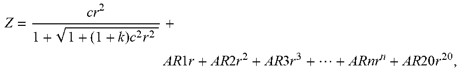
[0028] Detailed optical data and design parameters of the optical lens 10a are shown in Tables 1 and 2 below. In the following design examples of the invention, each aspheric surface satisfies the following equation:
Z = cr 2 1 + 1 + ( 1 + k ) c 2 r 2 + AR 1 r + AR 2 r 2 + AR 3 r 3 + + ARnr n + AR 20 r 20 , ##EQU00001##
where Z denotes a sag of an aspheric surface along the optical axis, c denotes a reciprocal of a radius of an osculating sphere, K denotes a Conic constant, r denotes a height of the aspheric surface measured in a direction perpendicular to the optical axis. Table 2 lists 4.sup.th, 6.sup.th, 8.sup.th, 10.sup.th, 12.sup.th, 14.sup.th, 16.sup.th, 18.sup.th and 20.sup.th order aspheric coefficients of the optical lens 10a. Note the data provided below are not used for limiting the invention, and those skilled in the art may suitably modify parameters or settings of the following embodiment with reference of the invention without departing from the scope or spirit of the invention.
TABLE-US-00001 TABLE 1 F/# = 2.0; EFL = 0.896(mm); TTL = 14.5(mm) LT = 12.04; FOV = 206 degrees; DL/LT = 0.27 EFL/LT = 0.074; IMH = 1.993(mm) radius of curvature interval refractive Abbe object surface (mm) (mm) index number description S1 10.509 0.608 1.83 42.7 L1(meniscus) S2 3.945 2.421 S3* -3.979 0.650 1.54 56.0 L2(aspheric) S4* 2.306 1.773 S5* -3.866 0.500 1.54 56.0 L3(aspheric) S6* 7.461 0.100 S7 4.576 2.044 1.85 23.8 L4(bi-convex) S8 -4.576 0.180 S9 INF. 0.383 aperture stop 14 S10* 2.694 0.668 1.64 23.0 L5(aspheric) S11* 0.652 0.008 1.50 56.0 adhesive S12* 0.652 2.705 1.54 56.0 L6(aspheric) S13* -1.895 0.100 S14 INF. 0.210 1.52 64.1 IR filter 16 S15 INF. 1.705 S16 INF. 0.400 1.52 64.1 cover glass 18 S17 INF. 0.045 S18 image plane 19
TABLE-US-00002 TABLE 2 S3* S4* S5* S6* k -96.062 -0.295 -89.878 -99.000 AR4 5.598E-02 1.657E-01 -2.369E-01 -4.160E-02 AR6 -3.217E-02 -1.434E-01 2.006E-01 8.072E-03 AR8 1.074E-02 4.676E-02 -1.510E-01 3.941E-02 AR10 -2.333E-03 8.238E-03 9.733E-02 -3.247E-02 AR12 3.415E-04 -1.436E-02 -4.482E-02 7.643E-03 AR14 -3.337E-05 5.958E-03 1.188E-02 9.810E-04 AR16 2.080E-06 -1.144E-03 -1.308E-03 -4.307E-04 AR18 -7.463E-08 8.498E-05 0.000E+00 0.000E+00 AR20 1.169E-09 0.000E+00 0.000E+00 0.000E+00 S10* S11* S12* S13* k -10.129 -1.272 -1.272 -0.290 AR4 2.066E-02 -3.445E-02 -3.445E-02 2.693E-02 AR6 -3.863E-02 7.747E-03 7.747E-03 1.277E-02 AR8 3.778E-02 7.685E-03 7.685E-03 -2.200E-02 AR10 -2.147E-02 -5.493E-03 -5.493E-03 1.716E-02 AR12 5.217E-03 1.458E-03 1.458E-03 -7.312E-03 AR14 0.000E+00 0.000E+00 0.000E+00 1.661E-03 AR16 0.000E+00 0.000E+00 0.000E+00 -1.586E-04 AR18 0.000E+00 0.000E+00 0.000E+00 0.000E+00 AR20 0.000E+00 0.000E+00 0.000E+00 0.000E+00
[0029] In the above Table 1, the field heading "interval" represents a distance between two adjacent surfaces along the optical axis 12 of the optical lens 10a. For example, an interval of the surface S1 is a distance between the surface S1 and the surface S2 along the optical axis 12, and an interval of the surface S17 is a distance between the surface S17 and the image plane 19 for visible light along the optical axis 12.
[0030] In the above table, the surface denoted by an asterisk is an aspheric surface, and a surface without the denotation of an asterisk is a spherical surface.
[0031] The radius of curvature is a reciprocal of the curvature. When a lens surface has a positive radius of curvature, the center of the lens surface is located towards the minified side.
[0032] When a lens surface has a negative radius of curvature, the center of the lens surface is located towards the magnified side. The concavity and convexity of each lens surface is listed in the above table and shown in corresponding figures.
[0033] The Symbol F/# shown in the above table is an aperture value of the aperture stop. When the optical lens is used in an optical projection system, the image plane is provided on a light valve, and, when the optical lens is used in an image pick-up system, the image plane is a sensing surface of a photosensor.
[0034] When the optical lens is used in an image pick-up system, the image circle refers to a diagonal length of an image on an image plane, and a semi-diagonal image height IMH listed in the above table equals half of the image circle.
[0035] A total lens length of the optical lens 10a is denoted as "LT" in the above table. Specifically, the total lens length LT is a distance along the optical axis 12 between a lens surface S1 closest to the magnified side and a lens surface S13 closest to the minified side (minified-side surface of the lens L6); that is, the total lens length LT is a length measured on the optical axis 12 between two outermost lens surfaces of the optical lens. In one embodiment, the total lens length LT of the optical lens is smaller than 15 mm.
[0036] A total track length of the optical lens 10a is denoted as "TTL" in the above table. Specifically, the total track length TTL is a distance along the optical axis 12 between a lens surface S1 closest to the magnified side (furthest from the image plane 19) and the image plane 19.
[0037] In this embodiment, FOV denoted in the above table is a light collection angle of the optical surface S1 closest to the magnified side; that is, the FOV is a full field of view measured diagonally. In one embodiment, the FOV is greater than 190 degrees and smaller than 230 degrees.
[0038] In one embodiment, the optical lens may include two lens groups, and the front lens group may include two lenses with negative refractive powers to increase light collection efficiency, where one of the two negative lenses is an aspheric lens, but the invention is not limited thereto. In one embodiment, an F-number of the optical lens is larger than or equal to about 1.8. The rear lens group may include at least one compound lens and at least one aspheric lens to correct monochromatic and chromatic aberrations, and thus a minimum distance between two lenses of the rear lens group along an optical axis is no more than 0.01 mm. The compound lens may be a cemented lens, a doublet lens, a triplet lens or even higher number lens configurations, and adjoining surfaces of each two adjacent lenses of the compound lens may have an identical or a similar radius of curvature. In one embodiment, a total number of lenses with refractive power in the optical lens is 5-8 (less than 9). In one embodiment, the optical lens may have three lenses with an Abbe number of greater than 50, and the three lenses may be made from plastic. In other embodiment, the optical lens may have three lenses with an Abbe number of greater than 55, and the rear lens group may have a cemented lens including at least one lens with an Abbe number of greater than 50.
[0039] In one embodiment, the optical lens may satisfy a condition of 0.2<DL/LT<0.38, a further condition of 0.21<DL/LT<0.36, and a still further condition of 0.22<DL/LT<0.34, where DL is a diameter of a lens surface closest to the image plane (a lens surface of the second lens group furthest from the first lens group), LT is a distance along the optical axis between a lens surface closest to the magnified side and a lens surface closest to the minified side. Meeting the above conditions may facilitate light converging capability of lenses to reduce the scope of image beams passing through lenses to match the size of a photosensor and thus allow for better optical performance in a limited space.
[0040] In one embodiment, the optical lens may satisfy a condition of 0.05<EFL/LT<0.1, a further condition of 0.054<EFL/LT<0.098, and a still further condition of 0.058<EFL/LT<0.096, where EFL is an effective focal length of the optical lens, and LT is a length measured on the optical axis between two outermost lens surfaces of the optical lens. Note that this criterion allows for an optimized proportion of a photosensor to a total lens length LT; that is, providing a proportionally longer LT when using a larger photosensor and a proportionally shorter LT when using a smaller photosensor.
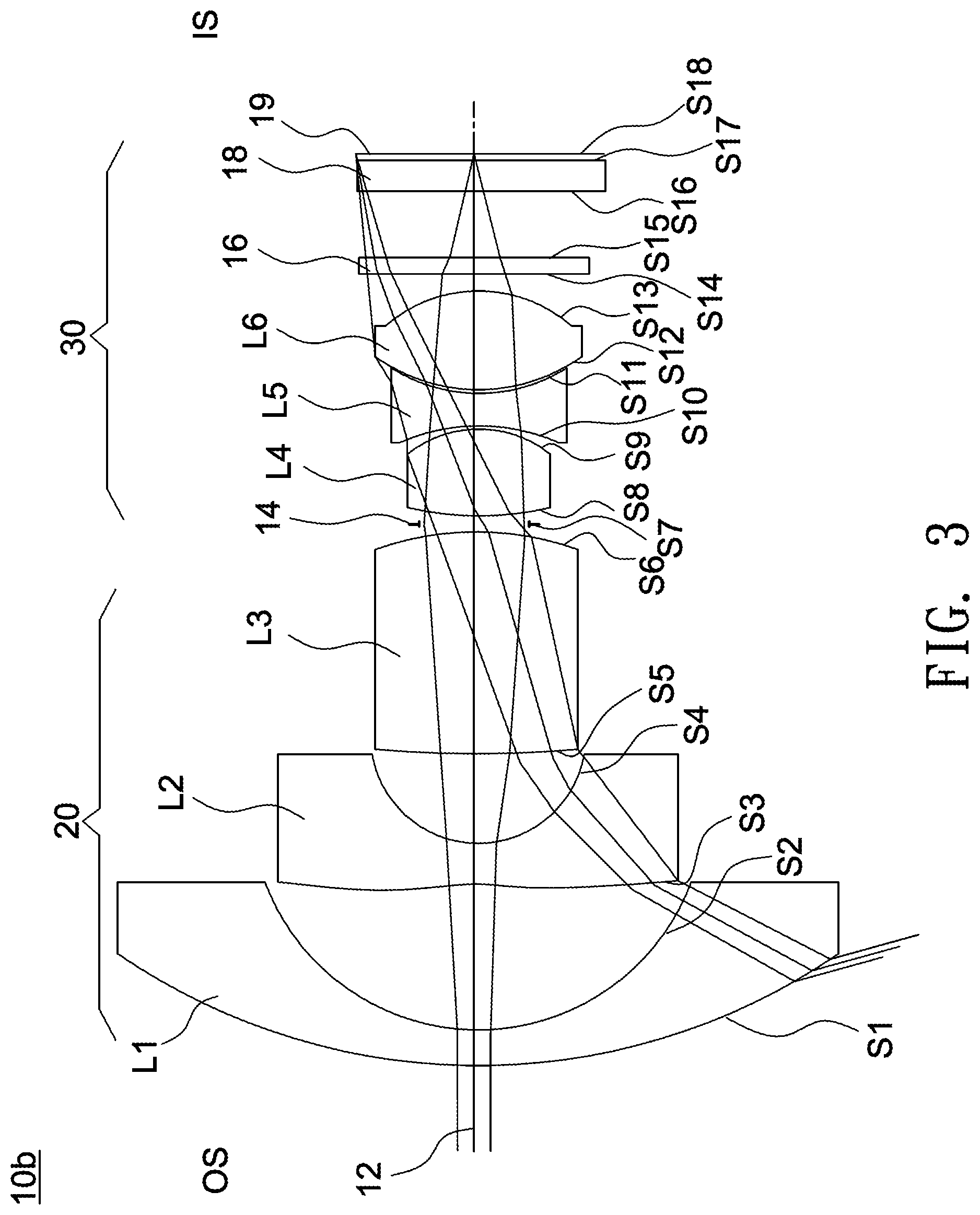
[0041] FIG. 3 shows a cross-sectional illustration of an optical lens according to a second embodiment of the invention. The optical lens 10b shown in FIG. 3 includes a first lens L1, a second lens L2, a third lens L3, an aperture stop 14, a fourth lens L4, a fifth lens L5 and a sixth lens L6. The first lens L1, the second lens L2, and the third lens L3 form a first lens group 20 (such as a front lens group) with a negative refractive power, and the fourth lens L4, the fifth lens L5 and the sixth lens L6 form a second lens group 30 (such as a rear lens group) with a positive refractive power.
[0042] In this embodiment, the refractive powers of the first lens L1 to the sixth lens L6 are negative, negative, positive, positive, negative and positive, and the second lens L2, the fourth lens L4, the fifth lens L5 and the sixth lens L6 are aspheric lenses made from plastic or glass. Further, in this embodiment, the diameter D1 of the surface S1 is 11.36 mm, and the diameter DL of the surface S13 is 3.276 mm. Detailed optical data and design parameters of the optical lens 10b are shown in Table 3 below.
TABLE-US-00003 TABLE 3 F/# = 2.0; EFL = 0.811(mm); TTL = 14.5(mm) LT = 12.348; FOV = 210 degrees; DL/LT = 0.27 EFL/LT = 0.066; IMH = 2.015(mm) radius of curvature interval refractive Abbe object surface (mm) (mm) index number description S1 10.126 0.568 1.87 40.7 L1(meniscus) S2 3.694 2.001 S3* -5.636 0.949 1.54 56.0 L2(aspheric) S4* 1.802 1.392 S5 53.543 3.495 1.95 18.0 L3(bi-convex) S6 -5.738 0.103 S7 INF. 0.315 aperture stop 14 S8* 4.651 1.331 1.54 56.0 L4(aspheric) S9* -1.491 0.030 S10* -3.246 0.500 1.66 20.4 L5(aspheric) S11* 1.850 0.105 S12* 2.156 1.559 1.54 56.0 L6(aspheric) S13* -1.898 0.292 S14 INF. 0.210 1.52 64.1 IR filter 16 S15 INF. 1.205 S16 INF. 0.400 1.52 64.1 cover glass 18 S17 INF. 0.045 S18 image plane 19
[0043] Table 4 lists aspheric coefficients and conic constant of each aspheric surface of the optical lens 10b according to the second embodiment of the invention.
TABLE-US-00004 TABLE 4 S3* S4* S8* S9* k 0.000 0.000 0.000 0.000 AR4 8.584E-02 5.212E-02 -2.352E-02 5.114E-02 AR6 -2.261E-02 1.781E-01 -2.671E-02 -4.579E-02 AR8 3.231E-03 -2.209E-01 1.620E-02 3.668E-02 AR10 -2.663E-04 1.069E-01 -1.254E-02 -7.438E-03 AR12 1.183E-05 -2.466E-02 0.000E+00 0.000E+00 ARM -2.174E-07 2.177E-03 0.000E+00 0.000E+00 AR16 0.000E+00 0.000E+00 0.000E+00 0.000E+00 AR18 0.000E+00 0.000E+00 0.000E+00 0.000E+00 AR20 0.000E+00 0.000E+00 0.000E+00 0.000E+00 S10* S11* S12* S13* k 0.000 0.000 0.000 0.000 AR4 -3.813E-02 -1.155E-01 -7.486E-02 2.818E-02 AR6 -7.042E-03 4.785E-02 8.536E-03 1.053E-02 AR8 1.614E-02 -1.552E-02 7.646E-03 -1.848E-02 AR10 -3.050E-03 1.322E-03 -3.287E-03 1.350E-02 AR12 0.000E+00 0.000E+00 4.431E-04 -4.489E-03 AR14 0.000E+00 0.000E+00 0.000E+00 7.129E-04 AR16 0.000E+00 0.000E+00 0.000E+00 0.000E+00 AR18 0.000E+00 0.000E+00 0.000E+00 0.000E+00 AR20 0.000E+00 0.000E+00 0.000E+00 0.000E+00
[0044] In the above Table 3, an interval of the surface S1 is a distance between the surface S1 and the surface S2 along the optical axis 12, an interval of the surface S2 is a distance between the surface S2 and the surface S3 along the optical axis 12, and an interval of the surface S17 is a distance between the surface S17 and the image plane 19 for visible light along the optical axis 12. The optical lens 10b may have three plastic lenses with an Abbe number of greater than 50.
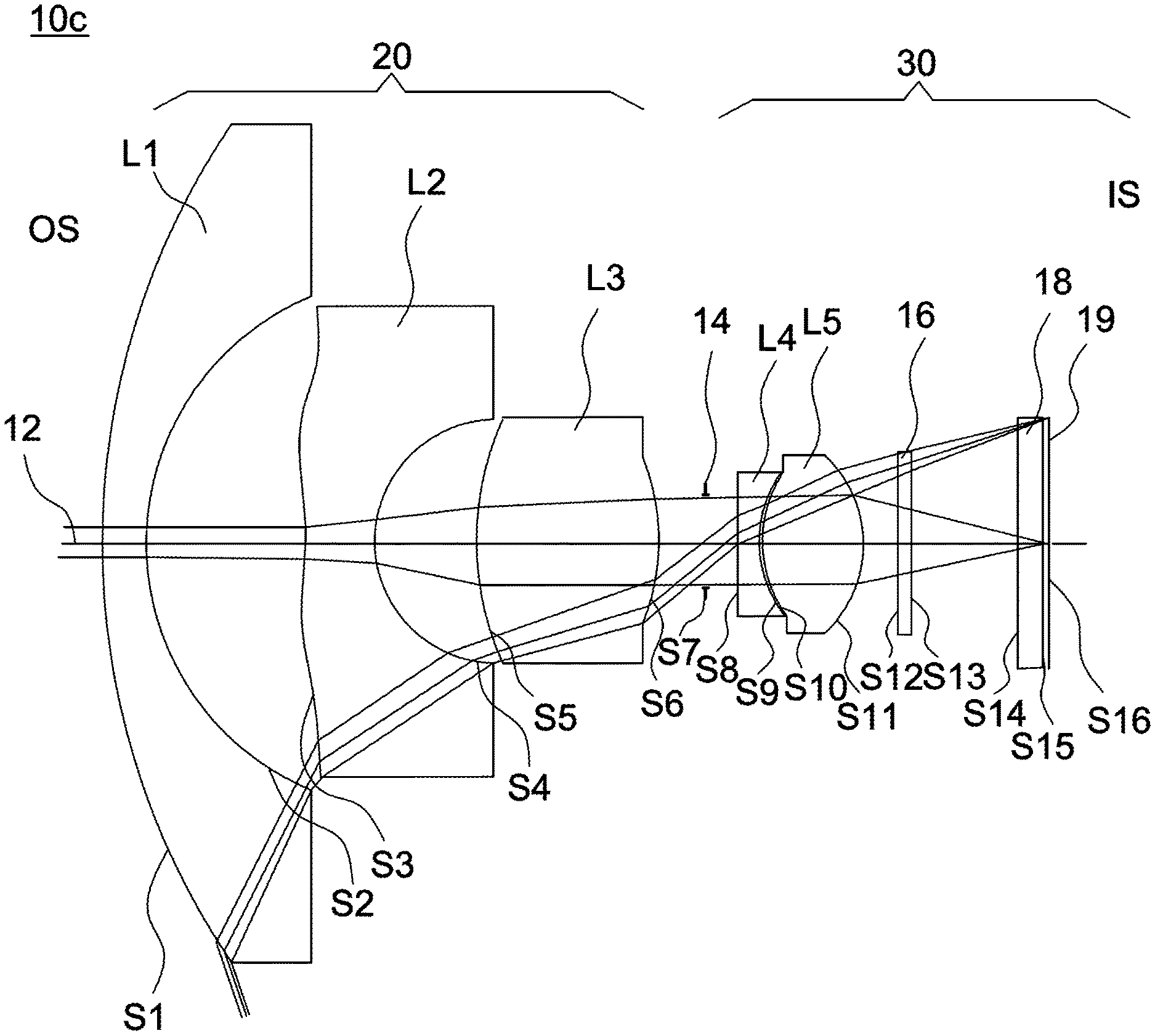
[0045] FIG. 5 shows a cross-sectional illustration of an optical lens according to a third embodiment of the invention. The optical lens 10c shown in FIG. 5 includes a first lens L1, a second lens L2, a third lens L3, an aperture stop 14, a fourth lens L4 and a fifth lens L5. The first lens L1, the second lens L2, and the third lens L3 form a first lens group 20 (such as a front lens group) with a negative refractive power, and the fourth lens L4 and the fifth lens L5 form a second lens group 30 (such as a rear lens group) with a positive refractive power. In this embodiment, the refractive powers of the first lens L1 to the fifth lens L5 are negative, negative, positive, negative and positive, and the second lens L2, the third lens L3, the fourth lens L4 and the fifth lens L5 are aspheric lenses made from plastic or glass. Further, in this embodiment, the diameter D1 of the surface S1 is 12.92 mm, and the diameter DL of the surface S11 is 2.76 mm. Detailed optical data and design parameters of the optical lens 10c are shown in Table 5 below.
TABLE-US-00005 TABLE 5 F/# = 2.0; EFL = 0.834(mm); TTL = 14.5(mm) LT = 11.665; FOV = 215 degrees; DL/LT = 0.24 EFL/LT = 0.07; IMH = 1.935(mm) radius of curvature interval refractive Abbe object surface (mm) (mm) index number description S1 11.547 0.646 1.87 40.7 L1(meniscus) S2 4.198 2.419 S3* -5.136 1.161 1.54 56.0 L2(aspheric) S4* 2.076 1.549 S5* 10.032 2.647 1.66 20.4 L3(aspheric) S6* -4.610 0.812 S7 INF. 0.474 aperture stop 14 S8* 15.312 0.500 1.66 20.4 L4(aspheric) S9* 1.801 0.030 S10* 1.541 1.427 1.54 56.0 L5(aspheric) S11* -1.519 0.533 S12 INF. 0.210 1.52 64.1 IR filter 16 S13 INF. 1.646 S14 INF. 0.400 1.52 64.1 cover glass 18 S15 INF. 0.045 S16 image plane 19
[0046] Table 6 lists aspheric coefficients and conic constant of each aspheric surface of the optical lens 10c according to the third embodiment of the invention.
TABLE-US-00006 TABLE 6 S3* S4* S5* S6* k 0.000 0.000 0.000 0.000 AR4 7.255E-02 6.978E-02 1.710E-02 1.232E-02 AR6 -1.440E-02 1.402E-01 2.491E-03 -4.867E-04 AR8 1.444E-03 -1.240E-01 -3.918E-03 -1.849E-03 AR10 -8.000E-05 4.116E-02 1.661E-03 2.923E-04 AR12 2.335E-06 -6.260E-03 -2.591E-04 0.000E+00 AR14 -2.743E-08 3.350E-04 0.000E+00 0.000E+00 AR16 0.000E+00 0.000E+00 0.000E+00 0.000E+00 AR18 0.000E+00 0.000E+00 0.000E+00 0.000E+00 AR20 0.000E+00 0.000E+00 0.000E+00 0.000E+00 S8* S9* S10* S11* k 0.000 0.000 0.000 0.000 AR4 2.275E-02 -1.588E-01 -2.587E-01 3.004E-02 AR6 -1.322E-01 5.965E-02 1.648E-01 1.431E-02 AR8 1.563E-01 -1.351E-02 -1.068E-01 -3.521E-02 AR10 -1.185E-01 -3.637E-03 4.536E-02 4.742E-02 AR12 3.054E-02 0.000E+00 -9.294E-03 -2.734E-02 AR14 0.000E+00 0.000E+00 0.000E+00 6.684E-03 AR16 0.000E+00 0.000E+00 0.000E+00 0.000E+00 AR18 0.000E+00 0.000E+00 0.000E+00 0.000E+00 AR20 0.000E+00 0.000E+00 0.000E+00 0.000E+00
[0047] In the above Table 5, an interval of the surface S1 is a distance between the surface S1 and the surface S2 along the optical axis 12, an interval of the surface S2 is a distance between the surface S2 and the surface S3 along the optical axis 12, and an interval of the surface S15 is a distance between the surface S15 and the image plane 19 for visible light along the optical axis 12. The optical lens 10c may have three lenses with an Abbe number of greater than 55.
[0048] FIGS. 7, 9, 11, 13, 15, 17 and 19 respectively show cross-sectional illustrations of optical lenses 10d, 10e, 10f, 10g, 10h, 10i and 10j according to various embodiments of the invention. The detailed optical data and design parameters of the optical lenses 10d, 10e, 10f, 10g, 10h, 10i and 10j are respectively shown in Tables 7, 9, 11, 13, 15, 17 and 19 below. Tables 8, 10, 12, 14, 16, 18 and 20 list aspheric coefficients and conic constant of each aspheric surface of the optical lenses 10d, 10e, 10f, 10g, 10h, 10i and 10j, respectively.
TABLE-US-00007 TABLE 7 radius of curvature interval refractive Abbe object surface (mm) (mm) index number description S1 12.051 0.630 1.80 39.6 L1(meniscus) S2 3.803 2.026 S3* 90.962 0.758 1.51 56.8 L2(aspheric) S4* 1.337 1.723 S5* -12.427 2.088 1.54 56.0 L3(aspheric) S6* 6.022 0.100 S7* 1.805 1.023 1.64 23.0 L4(aspheric) S8* -3.641 0.100 S9 INF. 0.256 aperture stop 14 S10* 20.383 0.604 1.64 23.1 L5(aspheric) S11* 0.573 3.015 1.54 56.0 L6(aspheric) S12* -1.486 0.100 S13* INF. 0.210 1.52 64.1 IR filter 16 S14 INF. 1.205 S15 INF. 0.400 1.52 64.1 cover glass 18 S16 INF. 0.045 S17 image plane 19
TABLE-US-00008 TABLE 8 S3* S4* S5* S6* S7* k -46.838 -0.587 -24.722 -31.527 0.823 AR4 -9.221E-03 -6.826E-02 -6.273E-02 -1.185E-01 -4.445E-02 AR6 4.511E-03 4.154E-02 2.857E-02 2.611E-02 1.491E-02 AR8 -8.833E-04 -5.328E-02 -4.191E-02 -8.234E-04 -2.948E-04 AR10 1.075E-04 5.375E-02 3.912E-02 -2.119E-04 -7.139E-03 AR12 -7.869E-06 -2.977E-02 -2.164E-02 0.000E+00 3.512E-03 AR14 3.097E-07 8.498E-03 6.165E-03 0.000E+00 5.362E-05 AR16 -4.854E-09 -9.702E-04 -6.795E-04 0.000E+00 0.000E+00 AR18 0.000E+00 0.000E+00 0.000E+00 0.000E+00 0.000E+00 AR20 0.000E+00 0.000E+00 0.000E+00 0.000E+00 0.000E+00 S8* S10* S11* S12* k -28.215 89.777 -0.942 -0.368 AR4 1.859E-01 1.748E-01 1.280E-01 5.618E-02 AR6 -7.617E-02 -3.893E-01 -9.108E-01 -1.484E-03 AR8 1.678E-01 7.875E-01 1.568E+00 -1.108E-02 AR10 -3.063E-01 -1.366E+00 -1.637E+00 1.382E-02 AR12 5.950E-01 1.716E+00 1.055E+00 -7.127E-03 AR14 -7.587E-01 -1.254E+00 -3.796E-01 1.824E-03 AR16 4.435E-01 3.865E-01 5.785E-02 -1.835E-04 AR18 0.000E+00 0.000E+00 0.000E+00 0.000E+00 AR20 0.000E+00 0.000E+00 0.000E+00 0.000E+00
TABLE-US-00009 TABLE 9 radius of curvature interval refractive Abbe object surface (mm) (mm) index number description S1 10.157 0.630 1.87 40.7 L1(meniscus) S2 3.957 2.062 S3* 45.072 0.847 1.51 56.8 L2(aspheric) S4* 1.146 1.976 S5* -23.265 2.568 1.64 23.2 L3(aspheric) S6* -2.404 0.100 S7 INF. 0.834 aperture stop 14 S8* 2.589 0.613 1.64 23.1 L4(aspheric) S9* 0.604 2.911 1.54 56.0 L5(aspheric) S10* -2.053 0.100 S11 INF. 0.210 1.52 64.1 IR filter 16 S12 INF. 1.205 S13 INF. 0.400 1.52 64.1 cover glass 18 S14 INF. 0.045 S15 image plane 19
TABLE-US-00010 TABLE 10 S3* S4* S5* S6* k 68.539 -0.556 52.121 0.657 AR4 2.525E-02 1.092E-02 -2.673E-02 8.604E-04 AR6 -1.009E-02 3.961E-03 -1.389E-02 -1.259E-02 AR8 2.123E-03 -2.895E-02 2.478E-02 5.107E-02 AR10 -2.609E-04 1.769E-02 -3.578E-02 -7.993E-02 AR12 1.898E-05 -8.351E-03 2.313E-02 6.525E-02 AR14 -7.609E-07 3.603E-03 -7.457E-03 -2.612E-02 AR16 1.298E-08 -7.497E-04 7.783E-04 4.053E-03 AR18 0.000E+00 0.000E+00 0.000E+00 0.000E+00 AR20 0.000E+00 0.000E+00 0.000E+00 0.000E+00 S8* S9* S10* k -3.672 -0.917 0.048 AR4 -2.797E-02 -2.439E-01 3.521E-02 AR6 2.379E-02 1.576E-01 1.295E-02 AR8 -1.077E-02 -1.179E-01 -2.402E-02 AR10 -7.420E-03 6.355E-02 1.883E-02 AR12 1.598E-02 -1.868E-02 -7.828E-03 AR14 -9.783E-03 1.862E-03 1.717E-03 AR16 2.071E-03 8.833E-05 -1.573E-04 AR18 0.000E+00 0.000E+00 0.000E+00 AR20 0.000E+00 0.000E+00 0.000E+00
TABLE-US-00011 TABLE 11 radius of curvature interval refractive Abbe object surface (mm) (mm) index number description S1 10.569 0.630 1.91 35.3 L1(meniscus) S2 3.916 2.564 S3* -3.739 1.063 1.54 56.0 L2(aspheric) S4* 1.855 1.436 S5* 9.461 2.344 1.64 23.5 L3(aspheric) S6* -2.735 0.730 S7 INF. 0.100 aperture stop 14 S8* 6.075 1.514 1.54 56.0 L4(aspheric) S9* -1.173 0.464 1.64 23.5 L5(aspheric) S10* 11.304 0.100 S11* 2.834 1.595 1.54 56.0 L6(aspheric) S12* -2.058 0.100 S13 INF. 0.210 1.52 64.1 IR filter 16 S14 INF. 1.205 S15 INF. 0.400 1.52 64.1 cover glass 18 S16 INF. 0.045 S17 image plane 19
TABLE-US-00012 TABLE 12 S3* S4* S5* S6* S8* k 0.000 0.000 0.000 0.000 0.000 AR4 6.537E-02 7.252E-02 1.813E-03 3.035E-02 6.968E-02 AR6 -1.567E-02 3.770E-02 1.419E-02 -1.002E-02 -2.332E-02 AR8 2.719E-03 -2.743E-02 -1.420E-02 2.241E-03 3.728E-02 AR10 -3.299E-04 1.128E-02 7.335E-03 -2.291E-04 -4.086E-02 AR12 2.596E-05 -6.205E-03 -2.148E-03 0.000E+00 1.888E-02 AR14 -1.162E-06 1.781E-03 2.421E-04 0.000E+00 0.000E+00 AR16 2.260E-08 -1.916E-04 0.000E+00 0.000E+00 0.000E+00 AR18 0.000E+00 0.000E+00 0.000E+00 0.000E+00 0.000E+00 AR20 0.000E+00 0.000E+00 0.000E+00 0.000E+00 0.000E+00 S9* S10* S11* S12* k 0.000 0.000 0.000 0.000 AR4 -3.639E-01 -1.952E-02 5.920E-04 4.346E-02 AR6 7.845E-02 2.232E-02 -3.108E-03 1.440E-02 AR8 2.108E-01 -7.608E-03 1.035E-03 -3.350E-03 AR10 -1.131E-01 1.226E-03 -1.040E-04 2.809E-04 AR12 0.000E+00 0.000E+00 0.000E+00 5.849E-05 AR14 0.000E+00 0.000E+00 0.000E+00 0.000E+00 AR16 0.000E+00 0.000E+00 0.000E+00 0.000E+00 AR18 0.000E+00 0.000E+00 0.000E+00 0.000E+00 AR20 0.000E+00 0.000E+00 0.000E+00 0.000E+00
TABLE-US-00013 TABLE 13 radius of curvature interval refractive Abbe object surface (mm) (mm) index number description S1 13.295 1.086 1.73 54.1 L1(meniscus) S2 3.827 2.012 S3* 4.885 1.107 1.54 56.0 L2(aspheric) S4* 0.751 0.918 S5* 2.175 2.792 1.66 20.4 L3(aspheric) S6* 6.911 0.268 S7 4.204 1.658 1.44 95.0 aperture stop 14/L4 (bi-convex) S8 -1.596 0.306 S9* 7.214 0.822 1.54 56.0 L5(aspheric) S10* -3.472 0.100 S11 INF. 0.210 1.52 64.2 IR filter 16 S12 INF. 1.459 S13 INF. 0.400 1.52 64.2 cover glass 18 S14 INF. 0.045 S15 image plane 19
TABLE-US-00014 TABLE 14 S3* S4* S5* S6* k -1.280 -0.985 -3.129 0.000 AR4 -1.855E-02 -4.028E-02 3.239E-02 3.972E-02 AR6 1.643E-03 1.046E-02 6.621E-03 1.276E-01 AR8 -8.625E-05 -4.937E-03 -2.684E-03 -2.445E-01 AR10 2.524E-06 7.835E-04 3.108E-04 2.392E-01 AR12 -3.314E-08 -1.229E-05 5.519E-06 -9.444E-26 AR14 1.310E-10 6.213E-07 6.681E-06 0.000E+00 AR16 0.000E+00 0.000E+00 0.000E+00 0.000E+00 AR18 0.000E+00 0.000E+00 0.000E+00 0.000E+00 AR20 0.000E+00 0.000E+00 0.000E+00 0.000E+00 S9* S10* k 20.100 2.978 AR4 -7.888E-03 3.743E-02 AR6 -4.631E-02 -3.690E-02 AR8 4.617E-02 2.833E-02 AR10 -3.220E-02 -1.243E-02 AR12 1.174E-02 2.746E-03 AR14 -1.936E-03 -2.143E-04 AR16 0.000E+00 0.000E+00 AR18 0.000E+00 0.000E+00 AR20 0.000E+00 0.000E+00
TABLE-US-00015 TABLE 15 radius of curvature interval refractive Abbe object surface (mm) (mm) index number description S1 10.235 1.067 1.95 32.3 L1(meniscus) S2 3.183 2.015 S3* 10.713 0.924 1.54 56.0 L2(aspheric) S4* 1.065 1.873 S5 4.942 1.628 1.76 27.5 L3(bi-convex) S6 -4.942 1.124 S7 INF. 0.072 aperture stop 14 S8* -146.369 0.843 1.54 56.0 L4(aspheric) S9* -2.087 0.050 S10* -14.987 0.600 1.64 23.5 L5(aspheric) S11* 1.158 2.044 1.54 56.0 L6(aspheric) S12* -2.435 0.100 S13 INF. 0.210 1.52 64.2 IR filter 16 S14 INF. 1.506 S15 INF. 0.400 1.52 64.2 cover glass 18 S16 INF. 0.044 S17 image plane 19
TABLE-US-00016 TABLE 16 S3* S4* S8* S9* k 0.000 -0.960 0.000 0.000 AR4 -1.296E-02 7.637E-03 -2.894E-02 -2.295E-02 AR6 1.441E-03 -2.172E-03 -1.850E-02 3.607E-02 AR8 -1.021E-04 2.472E-03 1.574E-02 -3.704E-02 AR10 3.131E-06 -5.152E-04 -1.332E-02 1.092E-02 AR12 -4.096E-21 8.981E-25 -4.370E-28 -4.443E-27 AR14 0.000E+00 0.000E+00 0.000E+00 0.000E+00 AR16 0.000E+00 0.000E+00 0.000E+00 0.000E+00 AR18 0.000E+00 0.000E+00 0.000E+00 0.000E+00 AR20 0.000E+00 0.000E+00 0.000E+00 0.000E+00 S10* S11* S12* k 0.000 -0.656 -0.677 AR4 -3.194E-02 -1.641E-02 -4.009E-03 AR6 2.222E-02 -4.412E-02 4.881E-05 AR8 -2.404E-02 9.714E-03 -2.793E-04 AR10 9.259E-03 -1.934E-03 2.366E-04 AR12 -5.368E-26 3.045E-25 5.544E-05 AR14 0.000E+00 1.148E-32 4.003E-28 AR16 0.000E+00 0.000E+00 0.000E+00 AR18 0.000E+00 0.000E+00 0.000E+00 AR20 0.000E+00 0.000E+00 0.000E+00
TABLE-US-00017 TABLE 17 radius of curvature interval refractive Abbe object surface (mm) (mm) index number description S1 9.155 0.650 1.95 32.3 L1(meniscus) S2 3.119 2.483 S3* -4.590 0.802 1.53 55.4 L2(aspheric) S4* 2.093 2.040 S5 4.610 2.130 1.90 31.3 L3(bi-convex) S6 -5.331 0.064 S7 INF. 1.084 aperture stop 14 S8* 4.448 0.525 1.64 23.2 L4(aspheric) S9* 0.711 0.008 1.50 65.0 adhesive S10* 0.711 2.300 1.53 56.0 L5(aspheric) S11* -2.134 0.372 S12 INF. 0.300 1.52 64.2 IR filter 16 S13 INF. 1.302 S14 INF. 0.400 1.52 64.2 cover glass 18 S15 INF. 0.045 S16 image plane 19
TABLE-US-00018 TABLE 18 S3* S4* S8* S9* k -18.532 -3.833 -17.822 -0.965 AR4 4.990E-03 8.744E-02 -2.517E-02 -9.415E-02 AR6 -5.330E-04 -1.432E-02 -6.305E-03 5.561E-03 AR8 2.986E-05 8.402E-03 1.034E-03 0.000E+00 AR10 -1.840E-06 -8.942E-04 0.000E+00 0.000E+00 AR12 -5.997E-09 -3.432E-04 0.000E+00 0.000E+00 AR14 1.158E-08 8.628E-05 0.000E+00 0.000E+00 AR16 0.000E+00 0.000E+00 0.000E+00 0.000E+00 AR18 0.000E+00 0.000E+00 0.000E+00 0.000E+00 AR20 0.000E+00 0.000E+00 0.000E+00 0.000E+00 S10* S11* k -0.965 -1.735 AR4 -9.415E-02 -1.283E-02 AR6 5.561E-03 -9.163E-03 AR8 0.000E+00 5.607E-03 AR10 0.000E+00 -2.305E-03 AR12 0.000E+00 5.510E-04 AR14 0.000E+00 -7.434E-05 AR16 0.000E+00 0.000E+00 AR18 0.000E+00 0.000E+00 AR20 0.000E+00 0.000E+00
TABLE-US-00019 TABLE 19 radius of curvature interval refractive Abbe object surface (mm) (mm) index number description S1 11.944 0.600 1.70 55.5 L1(meniscus) S2 3.950 2.478 S3* -2.396 0.700 1.51 56.8 L2(aspheric) S4* 5.821 1.563 S5* 9.036 3.581 1.61 26.0 L3(aspheric) S6* -4.267 -0.082 S7 INF. 0.661 aperture stop 14 S8* 1.681 0.544 1.64 23.1 L4(aspheric) S9* 0.620 2.835 1.53 55.4 L5(aspheric) S10* -2.317 0.352 S11 INF. 0.300 1.52 64.2 IR filter 16 S12 INF. 0.527 S13 INF. 0.400 1.52 64.2 cover glass 18 S14 INF. 0.045 S15 image plane 19
TABLE-US-00020 TABLE 20 S3* S5* S6* S8* k -13.687 12.285 -1.340 -0.149 AR4 1.538E-02 -2.162E-02 -5.499E-02 -8.593E-02 AR6 -1.367E-03 1.293E-03 2.627E-02 1.969E-02 AR8 5.913E-05 2.850E-04 -1.363E-02 -8.101E-03 AR10 -9.730E-07 -1.294E-03 4.561E-03 6.129E-04 AR12 0.000E+00 0.000E+00 0.000E+00 0.000E+00 ARM 0.000E+00 0.000E+00 0.000E+00 0.000E+00 AR16 0.000E+00 0.000E+00 0.000E+00 0.000E+00 AR18 0.000E+00 0.000E+00 0.000E+00 0.000E+00 AR20 0.000E+00 0.000E+00 0.000E+00 0.000E+00 S4* S9* S10* k 7.755E+00 -1.031E+00 -4.416E+01 AR1 0.000E+00 0.000E+00 0.000E+00 AR2 0.000E+00 0.000E+00 1.644E-01 AR3 0.000E+00 4.580E-02 -1.935E-01 AR4 1.503E-01 -7.514E-02 5.056E-02 AR5 -3.632E-02 -9.335E-02 -2.653E-02 AR6 -6.418E-02 1.296E-01 6.820E-02 AR7 -6.090E-03 6.053E-03 -9.894E-02 AR8 6.541E-02 -6.847E-02 1.050E-01 AR9 0.00743858 0.03240348 -0.074004127 AR10 -0.0346061 -0.0096494 0.031358759 AR11 -0.001 0.012 -0.010 AR12 0.010 -0.014 0.002 AR13 -2.635E-04 8.136E-03 3.436E-04 AR14 -1.078E-03 -1.894E-03 -2.738E-04
[0049] Table 21 lists various design parameters of the optical lenses 10a-10j according to the first to the tenth embodiments. The definition of each parameter listed in Table 21 has been described in earlier sections, thus not repeatedly described here for brevity.
TABLE-US-00021 TABLE 21 Optical Material EFL lens Cemented lens Refractive power (G: glass/P: plastic) for visible light (mm) 10a L5&L6 ---+-+ G P P G P P 0.896 10b --++-+ G P G P P P 0.811 10c --+-+ G P P P P 0.834 10d L5&L6 ---+-+ G P P P P P 0.885 10e L4&L5 --+-+ G P P P P 0.872 10f L4&L5 --++-+ G P P P P P 0.848 10g --+++ G P P G P 0.905 10h L5&L6 --++-+ G P G P P P 1.011 10i L4&L5 --+-+ G P G P P 1.105 10j L4&L5 --+-+ G P P P P 1.203 Optical TTL LT IMH D1 DL lens F# FOV (mm) (mm) (mm) (mm) (mm) DL/LT EFL/LT 10a 2 206 14.5 12.04 1.993 12.06 3.274 0.272 0.074 10b 2 210 14.5 12.348 2.015 11.36 3.276 0.265 0.066 10c 2 215 14.5 11.665 1.935 12.92 2.76 0.237 0.071 10d 2 206 14.282 12.322 2.06 12.0 3.326 0.270 0.072 10e 2 206 14.5 12.54 2.075 12.0 3.394 0.271 0.070 10f 2 215 14.5 12.54 2.12 12.0 3.532 0.282 0.068 10g 2 218 13.18 10.97 2.01 12.84 3.198 0.292 0.082 10h 2 218 14.5 12.24 1.998 11.13 3.232 0.264 0.083 10i 2 207 14.5 12.087 2.01 10.01 3.08 0.255 0.091 10j 2.1 201 14.5 12.88 1.963 12.76 3.418 0.265 0.093
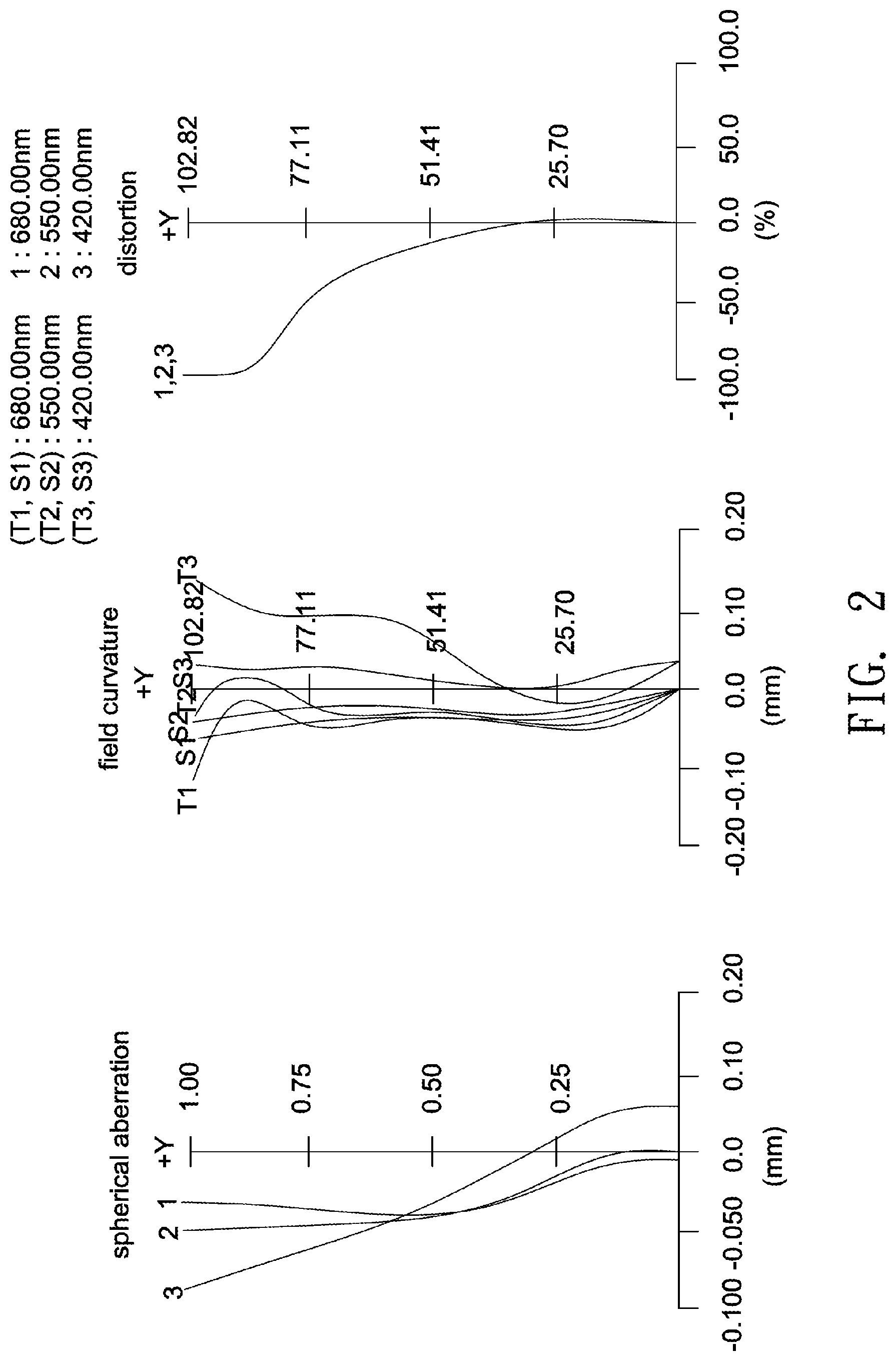
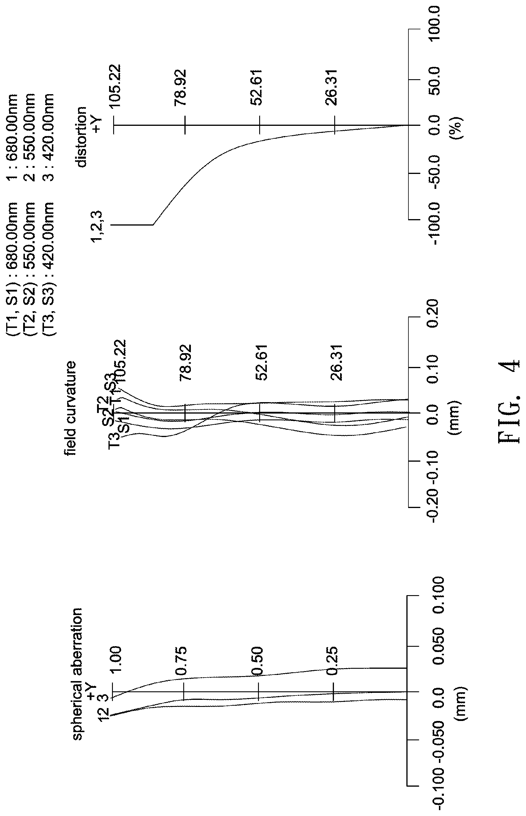
[0050] FIGS. 2, 4, 6, 8, 10, 12, 14, 16, 18 and 20 illustrate spherical aberration, field curvature and distortion plots of the optical lenses 10a, 10b, 10c, 10d, 10e, 10f, 10g, 10h, 10i and 10j, respectively. The simulated results shown in FIGS. 2, 4, 6, 8, 10, 12, 14, 16, 18 and 20 are within permitted ranges specified by the standard, which indicates the optical lenses 10a-10j according to the above embodiments may achieve good imaging quality.
[0051] According to the above embodiments, the optical lens may achieve high optical performance, low thermal shift, wide viewing angles, low fabrication costs and good imaging quality. Further, a total number of lenses can be reduced to 5-8, and a total track length TTL can be decreased to be smaller than 18 mm. Therefore, an optical lens having large effective aperture, high resolution, wide viewing angles, low thermal shift, reduced occupied space, low fabrication costs and good imaging quality can be provided.
[0052] Though the embodiments of the invention and design parameters in the tables have been presented for purposes of illustration and description, they are not intended to be exhaustive or to limit the invention. Accordingly, many modifications and variations without departing from the spirit of the invention or essential characteristics thereof will be apparent to practitioners skilled in this art. For example, the number of all lenses of each lens group or optical parameters such as refractive power for each lens may be changed, or a lens without affecting the overall optical performance may be additionally provided. It is intended that the scope of the invention be defined by the claims appended hereto and their equivalents in which all terms are meant in their broadest reasonable sense unless otherwise indicated.
* * * * *
D00000
D00001
D00002
D00003
D00004
D00005
D00006
D00007
D00008
D00009
D00010
D00011
D00012
D00013
D00014

D00015
D00016

D00017

D00018

D00019

D00020
XML
uspto.report is an independent third-party trademark research tool that is not affiliated, endorsed, or sponsored by the United States Patent and Trademark Office (USPTO) or any other governmental organization. The information provided by uspto.report is based on publicly available data at the time of writing and is intended for informational purposes only.
While we strive to provide accurate and up-to-date information, we do not guarantee the accuracy, completeness, reliability, or suitability of the information displayed on this site. The use of this site is at your own risk. Any reliance you place on such information is therefore strictly at your own risk.
All official trademark data, including owner information, should be verified by visiting the official USPTO website at www.uspto.gov. This site is not intended to replace professional legal advice and should not be used as a substitute for consulting with a legal professional who is knowledgeable about trademark law.