Perimeter Security System with Non-lethal Detainment Response
Norris; Elwood
U.S. patent application number 16/702136 was filed with the patent office on 2020-06-18 for perimeter security system with non-lethal detainment response. The applicant listed for this patent is Wrap Technologies, Inc.. Invention is credited to Elwood Norris.
| Application Number | 20200191532 16/702136 |
| Document ID | / |
| Family ID | 71071474 |
| Filed Date | 2020-06-18 |


| United States Patent Application | 20200191532 |
| Kind Code | A1 |
| Norris; Elwood | June 18, 2020 |
Perimeter Security System with Non-lethal Detainment Response
Abstract
A method is provided of remotely detaining a subject with a temporary restraint. The method includes monitoring at least a portion of a perimeter of an area, and receiving an event signal generated as a result of remote movement or presence of a subject. A projectile is be remotely launched from a launcher a toward the subject, the projectile including a pair of pellets and a tether connecting the pellets. The projectile is capable of at least temporarily detaining the subject when wrapped about the subject.
| Inventors: | Norris; Elwood; (Poway, CA) | ||||||||||
| Applicant: |
|
||||||||||
|---|---|---|---|---|---|---|---|---|---|---|---|
| Family ID: | 71071474 | ||||||||||
| Appl. No.: | 16/702136 | ||||||||||
| Filed: | December 3, 2019 |
Related U.S. Patent Documents
| Application Number | Filing Date | Patent Number | ||
|---|---|---|---|---|
| 62775158 | Dec 4, 2018 | |||
| Current U.S. Class: | 1/1 |
| Current CPC Class: | F42B 12/68 20130101; F41H 13/0006 20130101; F42B 12/66 20130101 |
| International Class: | F41H 13/00 20060101 F41H013/00; F42B 12/66 20060101 F42B012/66; F42B 12/68 20060101 F42B012/68 |
Claims
1. A method of remotely detaining a subject with a temporary restraint, comprising: monitoring at least a portion of a perimeter of an area; receiving an event signal generated as a result of remote movement or presence of a subject; and remotely launching from a launcher a projectile toward the subject, the projectile including a pair of pellets and a tether connecting the pellets, the projectile being capable of at least temporarily detaining the subject when wrapped about the subject.
2. The method of claim 1, wherein the event signal is generated by a motion sensor.
3. The method of claim 1, wherein monitoring utilizes a video surveillance system.
4. The method of claim 3, wherein the event signal is generated manually by personnel based on the video surveillance.
5. The method of claim 1, further comprising transmitting an alert of the launch to a command center.
6. The method of claim 1, further comprising identifying data associated with the launcher, the identifying data including at least a location of the launcher.
7. The method of claim 6, further comprising dispatching personnel to a location of the launch.
8. A system of remotely detaining a subject with a temporary restraint, comprising: a sensor system operable to monitor a perimeter of an area; an event signal generator operable to generate an event signal if movement or presence of a subject is detected by the sensor system; and a launcher, operable to remotely launch a projectile toward the subject, the projectile including a pair of pellets and a tether connecting the pellets, the projectile being capable of at least temporarily detaining the subject when wrapped about the subject.
9. The system of claim 8, wherein the sensor system includes a motion sensor.
10. The system of claim 8, wherein the sensor system includes a video surveillance system.
11. The system of claim 10, wherein the launcher is activated manually by personnel based on the video surveillance.
12. The system of claim 8, further comprising a transmitter operable to transmit an alert of the launch to a command center.
13. The system of claim 8, further comprising identifying data associated with the launcher, the identifying data including at least a location of the launcher.
14. The system of claim 13, further comprising personnel being dispatchable to a location of the launch.
15. The system of claim 8, wherein the launcher is moveable relative to a surrounding environment to enable the launcher to target one or more subjects in a range of positions.
Description
PRIORITY CLAIM
[0001] Priority is claimed of and to U.S. Provisional Patent Application Ser. No. 62/775,158, filed Dec. 4, 2018, which is hereby incorporated herein by reference in its entirety.
BACKGROUND OF THE INVENTION
Field of the Invention
[0002] The present invention relates generally to non-lethal, near-range weapons systems to aid in temporarily detaining, immobilizing, impeding or subduing hostile or fleeing subjects.
Related Art
[0003] It has been recognized for some time that police and military personnel can benefit from the use of weapons and devices other than firearms to deal with some hostile situations. While firearms are necessary tools in law enforcement, they provide a level of force that is sometimes unwarranted. In many cases, law enforcement personnel may wish to deal with a situation without resorting to use of a firearm. It is generally accepted, however, that engaging in hand-to-hand combat is not a desirable alternative.
[0004] For these and other reasons, non-lethal, generally near-range devices for detaining subjects have been used with some success. Examples of such devices are described in U.S. Pat. No. 10,107,599, to the present inventor. While these devices, and devices like these, have proven effective, they have to date been restricted to usage where law enforcement or other personnel are near the subject of interest. As such, effective, non-lethal solutions for remotely engaging subjects continue to be sought.
SUMMARY OF THE INVENTION
[0005] In accordance with one aspect of the invention, a method is provided of remotely detaining a subject with a temporary restraint. The method can include monitoring a perimeter of an area; and receiving an event signal generated by remote movement or presence of a subject. A projectile can be remotely launched from a launcher toward the subject. The projectile can include a pair of pellets and a tether connecting the pellets. The projectile can be capable of at least temporarily detaining the subject when wrapped about the subject.
[0006] In accordance with another aspect of the technology, a system is provided of remotely detaining a subject with a temporary restraint. The detaining system can include a sensor system operable to monitor a perimeter of an area. An event signal generator can be operable to generate an event signal if movement or presence of a subject is detected by the sensor system. A launcher can be operable to remotely launch a projectile toward the subject. The projectile can include a pair of pellets and a tether connecting the pellets. The projectile can be capable of at least temporarily detaining the subject when wrapped about the subject.
[0007] Additional features and advantages of the invention will be apparent from the detailed description which follows, taken in conjunction with the accompanying drawings, which together illustrate, by way of example, features of the invention.
BRIEF DESCRIPTION OF THE DRAWINGS
[0008] The following drawings illustrate exemplary embodiments for carrying out the invention. Like reference numerals refer to like parts in different views or embodiments of the present invention in the drawings.
[0009] FIG. 1 is a top perspective view of a hand-held, near-range launcher in accordance with an aspect of the present invention, shown in an exploded condition with a projectile casing being removed the device;
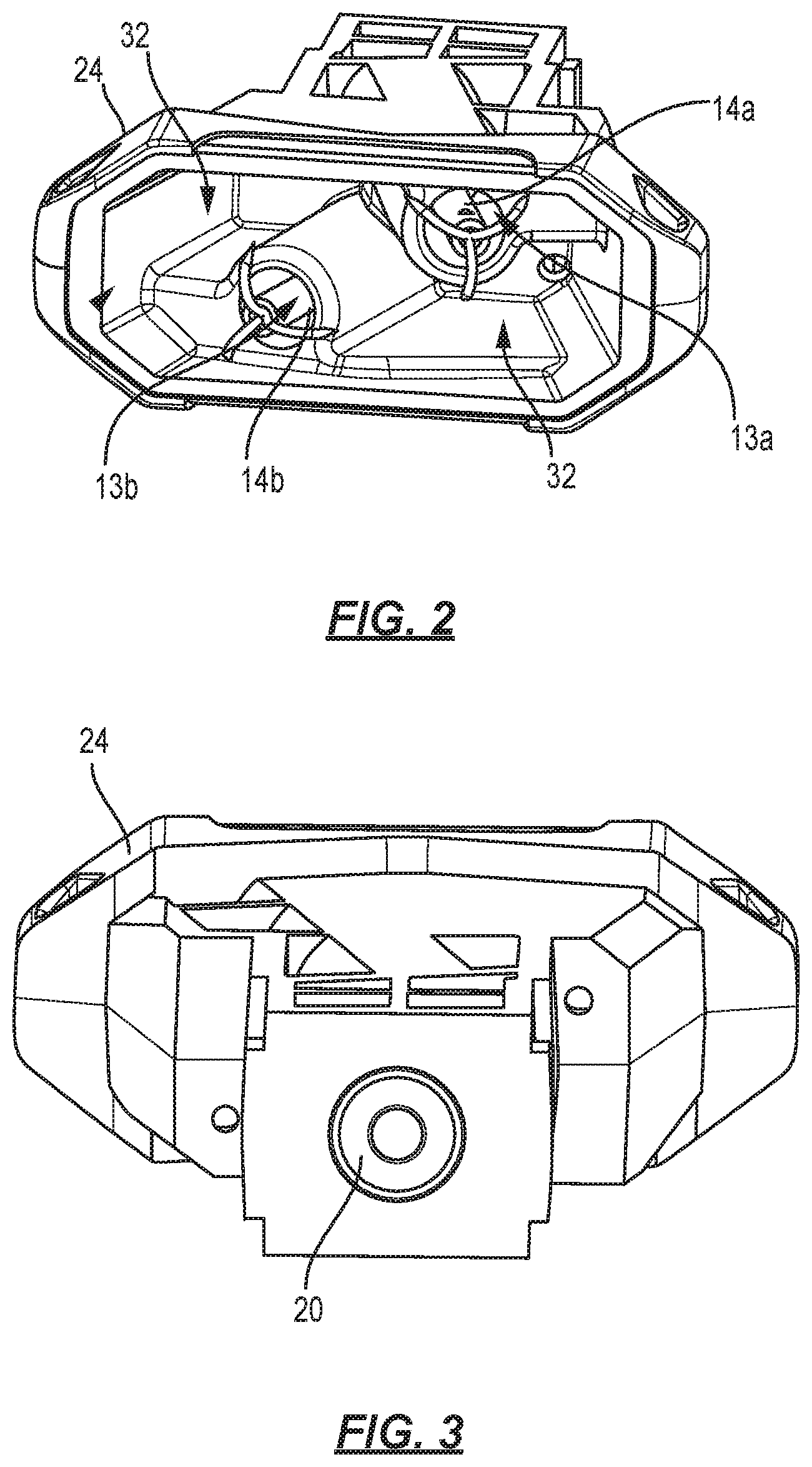
[0010] FIG. 2 is a front view of the projectile casing of FIG. 1;
[0011] FIG. 3 is a rear view of the projectile casing of FIG. 1;
[0012] FIG. 4 is a front view of a portion of a subject in accordance with an embodiment of the invention, shown immediately prior to an entangling projectile engaging the subject's legs;
[0013] FIG. 5 is a side, schematic view of a stationary launcher assembly in accordance with an aspect of the invention; and
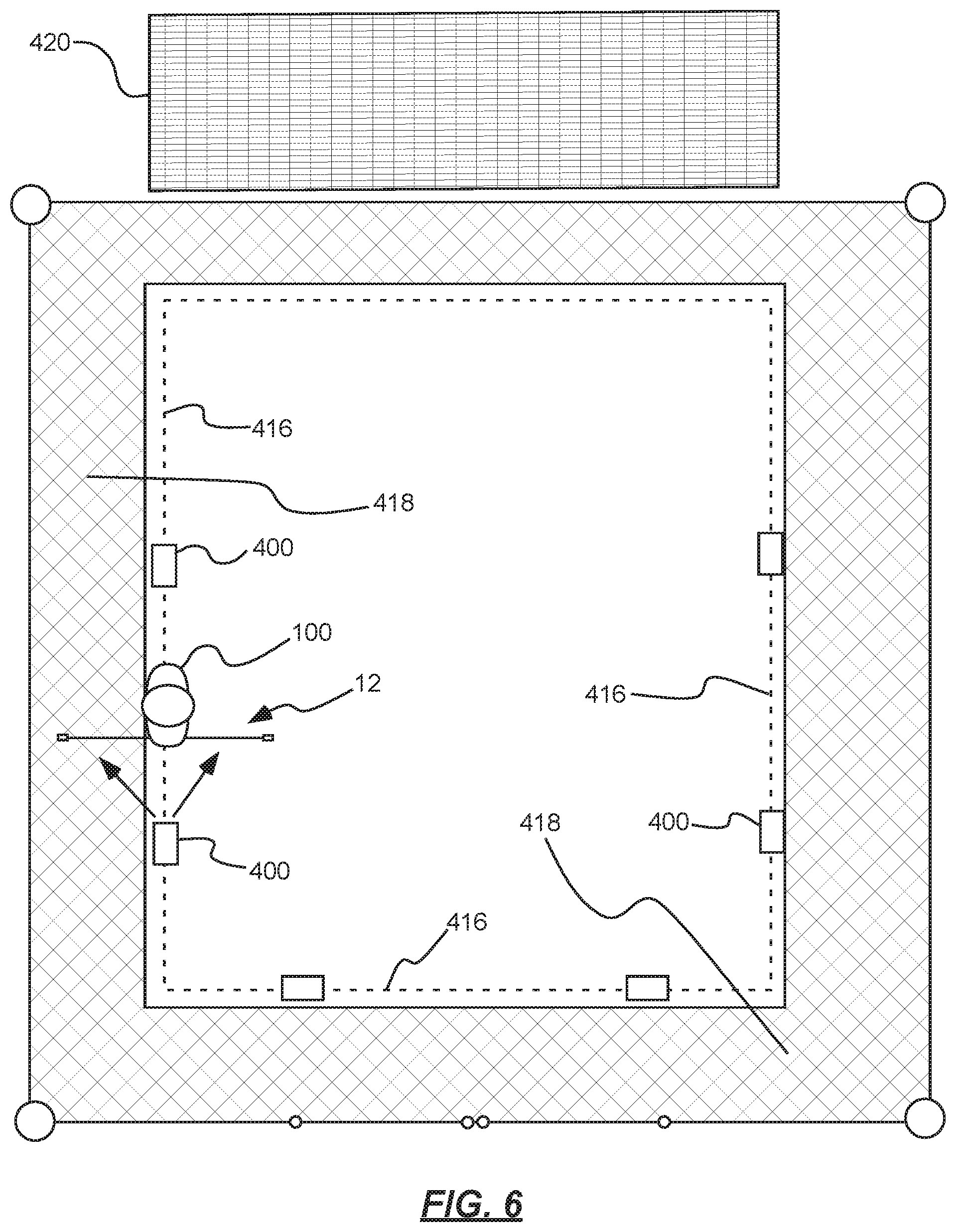
[0014] FIG. 6 is a top view of an area having a perimeter monitored in accordance with the present technology.
DETAILED DESCRIPTION
[0015] Reference will now be made to the exemplary embodiments illustrated in the drawings, and specific language will be used herein to describe the same. It will nevertheless be understood that no limitation of the scope of the invention is thereby intended. Alterations and further modifications of the inventive features illustrated herein, and additional applications of the principles of the inventions as illustrated herein, which would occur to one skilled in the relevant art and having possession of this disclosure, are to be considered within the scope of the invention.
Definitions
[0016] As used herein, the singular forms "a" and "the" can include plural referents unless the context clearly dictates otherwise. Thus, for example, reference to "a camera" can include one or more of such cameras, if the context dictates.
[0017] As used herein, the term "substantially" refers to the complete or nearly complete extent or degree of an action, characteristic, property, state, structure, item, or result. As an arbitrary example, an object that is "substantially" enclosed is an article that is either completely enclosed or nearly completely enclosed. The exact allowable degree of deviation from absolute completeness may in some cases depend upon the specific context. However, generally speaking the nearness of completion will be so as to have the same overall result as if absolute and total completion were obtained. The use of "substantially" is equally applicable when used in a negative connotation to refer to the complete or near complete lack of an action, characteristic, property, state, structure, item, or result. As another arbitrary example, a composition that is "substantially free of" an ingredient or element may still actually contain such item so long as there is no measurable effect as a result thereof.
[0018] As used herein, the term "about" is used to provide flexibility to a numerical range endpoint by providing that a given value may be "a little above" or "a little below" the endpoint.
[0019] Relative directional terms can sometimes be used herein to describe and claim various components of the present invention. Such terms include, without limitation, "upward," "downward," "horizontal," "vertical," etc. These terms are generally not intended to be limiting, but are used to most clearly describe and claim the various features of the invention. Where such terms must carry some limitation, they are intended to be limited to usage commonly known and understood by those of ordinary skill in the art in the context of this disclosure.
[0020] As used herein, a plurality of items, structural elements, compositional elements, and/or materials may be presented in a common list for convenience. However, these lists should be construed as though each member of the list is individually identified as a separate and unique member. Thus, no individual member of such list should be construed as a de facto equivalent of any other member of the same list solely based on their presentation in a common group without indications to the contrary.
[0021] Numerical data may be expressed or presented herein in a range format. It is to be understood that such a range format is used merely for convenience and brevity and thus should be interpreted flexibly to include not only the numerical values explicitly recited as the limits of the range, but also to include all the individual numerical values or sub-ranges encompassed within that range as if each numerical value and sub-range is explicitly recited. As an illustration, a numerical range of "about 1 to about 5" should be interpreted to include not only the explicitly recited values of about 1 to about 5, but also include individual values and sub-ranges within the indicated range. Thus, included in this numerical range are individual values such as 2, 3, and 4 and sub-ranges such as from 1-3, from 2-4, and from 3-5, etc., as well as 1, 2, 3, 4, and 5, individually.
[0022] This same principle applies to ranges reciting only one numerical value as a minimum or a maximum. Furthermore, such an interpretation should apply regardless of the breadth of the range or the characteristics being described.
[0023] Invention
[0024] The present technology relates generally to non-lethal, near-range weapons systems that can be effectively used as an aid in impeding the progress of or detaining aggressive or fleeing subjects. Devices in accordance with the present technology can be advantageously used to temporarily impede a subject's ability to stand, walk, run, or use his or her arms. These options can be beneficial in cases where law enforcement, security personnel or military personnel wish to detain a subject, but do not wish to use lethal or harmful force or to engage in close proximity, hand-to-hand combat.
[0025] FIGS. 1 through 3 illustrate one exemplary launcher 10 that can be used in accordance with the present technology. This launcher is used to expel an entangling projectile toward a subject: after contacting the subject, the entangling projectile wraps about arms or legs of the subject to temporarily restrain or subdue the subject. The launcher 10 is similar in operation and design as those disclosed in patents and patent applications to the present inventor, such as U.S. Pat. No. 10,036,615, U.S. patent application Ser. No. 15/399,537 and U.S. patent application Ser. No. 15/467,958, all of which are hereby incorporated herein by reference in their entirety. Reference is made to these patents and publications for additional information about the launcher shown in FIGS. 1 through 3.
[0026] In the example shown, launcher 10 generally includes an entangling projectile (12 in FIG. 4) that includes a pair of pellets 14a, 14b, and a tether (16 in FIG. 4) connecting the pellets. A projectile casing 24 can be provided that can include a pair of sockets 13a, 13b (see FIG. 3). Each socket can be sized and shaped to carry one of the pair of pellets: in the examples shown, socket 13a carries pellet 14a and socket 13b carries pellet 14b.
[0027] The projectile casing 24 can include a selectively activatable power source or pressure source 20 (FIG. 3). The pressure source can be capable of expelling the entangling projectile from the projectile casing toward a subject. The system can also include a launcher body 22 that can carry a control system (not shown in detail) that can be operable to activate the pressure source to expel the entangling projectile from the projectile casing toward the subject.
[0028] While not so required, the projectile casing 24 can be removably engageable with the launcher body 22 to allow removal of the projectile casing from the launcher after expulsion of the entangling projectile from the projectile casing. In the example shown, launcher 10 includes a user input interface, or in this case a trigger 42, that is in communication with the control system. The control system is in turn in communication with the power or pressure source (20 in FIG. 3). Generally, activation of the user input, or trigger, causes the control system to activate the pressure or power source, which results in expulsion of the entangling projectile from the projectile casing 22.
[0029] In the example shown, once the projectile has been deployed from a particular projectile casing, that casing can be removed and a fresh projectile casing with a preinstalled entangling projectile and pressure or power source can be installed within the launcher. Activation of a first casing and replacement with a fresh casing can be achieved in a matter of seconds. Thus, law enforcement, security, military, etc., personnel can very rapidly exchange a spent projectile casing with a fresh projectile casing that is loaded and ready to activate by the launcher.
[0030] FIG. 2 illustrates a front view of the casing 44. In this view, pellets 14a, 14b can be seen stored, ready for use, in sockets 13a, 13b, respectively. Tether storage compartments 32 can be provided and can consist of shaped depressions formed in the projectile casing to allow the tether (16 in FIG. 4) to be stored adjacent the pellets prior to use.
[0031] In the example shown in FIGS. 1-3, the power or pressure source 20 comprises a cartridge blank. This type of pressure source is well known to contain gunpowder that is typically activated by striking a primer formed in the cartridge. The blank cartridge contains no slug: deployment of the cartridge results only in a high-pressure wave being directed from the projectile casing. This high-pressure wave is utilized by the present technology to propel the entangling projectile from the system at high velocity. In one embodiment of the invention, the cartridge blank can be irremovably attached to the cartridge such that the cartridge is a single actuation cartridge. In this manner, installation of the cartridge can be done in a controlled manufacturing environment, to ensure the proper cartridge is used, that the cartridge is properly installed, and that the casing 24 is otherwise ready for use. The cartridge can be secured to the casing by adhesive, mechanical crimp, etc.
[0032] Operation of the entangling projectile is shown generally in FIG. 4: after being released by a launcher, the projectile 12 travels toward a subject 100. As the projectile travels toward the subject, pellets 14 travel away from one another, resulting in the tether 16 being pulled substantially taught between the two. Once the projectile engages the subject (in the example shown the subject's legs are engaged), the pellets and tether wrap about the subject and thereby temporarily entangle and/or disable the subject.
[0033] A variety of differing pellet and tether combinations can be utilized in the present technology. In the examples shown in FIG. 4, the projectile 12 is shown with two generic pellets 14 connected by a single tether 16. While more than two pellets can be utilized, the examples shown herein include only two. In some embodiments, the invention is limited to two, and only two, pellets connected by a single tether. In one aspect, the invention consists of two pellets and a single tether. In one aspect, the invention consists essentially of two pellets and a single tether. It has been found that limiting the number of pellets to two results in a more effective deployment system: the risk of tangling of the tether 16 is diminished and the pellets spread apart from one another much more cleanly and quickly after being deployed from the launcher. This results in a more consistent trajectory after deployment. This arrangement can also allow, with the proper launcher configuration, the projectiles to be more accurately directed toward a subject.
[0034] The launcher shown in FIGS. 1-3 is generally intended for use as a hand-held launcher, to be wielded similarly to a pistol. While such devices have proven very successful in near-range engagement with subjects, the present technology provides solutions that can be used remotely. For example, turning now to FIGS. 5 and 6, in one aspect of the invention, a stationary launcher assembly 400 is shown that can be used in a remote monitoring system. The launcher assembly can be configured to be mounted upon a suitable stand, or upon other structure, as a stand-alone, remote unit. The launcher assembly can include, without limitation, a launcher 410 that can include, as described and shown in more detail in connection with FIGS. 1 through 3, a projectile that can include a pair of pellets and a tether connecting the pellets. As above, the projectile can be capable of at least temporarily detaining the subject when wrapped about the subject.
[0035] In addition to the launcher 410, the assembly 400 can also include a sensor system 412 that can be operable to monitor a perimeter of an area. The sensor system can include one or more sensors operable to detect the presence or movement of a subject. Suitable examples include, without limitation, common motion-detecting devices such as passive infrared sensors, microwave detectors, area reflective detectors, ultrasonic detectors, vibration detectors, etc. The sensor system can also include video cameras and the like that can provide images to a remote processing center. The images can be either analyzed by a computing system to detect the presence of a subject, or by human personnel. The image data can be viewed in real-time and/or saved for later access. The sensor system can also include range-finding sensors that can determine a distance and orientation of a subject relative
[0036] The sensor system 412 is generally operable to detect when a subject is present and can initiate the generation of an event signal indicating the presence of a subject. An event signal generator 414 is also provided that can be operable to generate an event signal in response to detection of a subject by the sensor system. Once the event signal has been generated, a signal can be provided to the launcher 410 to remotely launch a projectile toward the subject.
[0037] The launcher 410 can be stationary or mounted on a moveable platform such that it can be positioned remotely. This can be accomplished either manually or automatically to target or track a subject within the target area such that the projectile can more precisely engage a subject. A variety of suitable systems can be used to aim the launcher and can be controlled remotely by a computer system and/or a human operator.
[0038] FIG. 6 illustrates a system for monitoring a perimeter of an area in accordance with one example of the present technology. Note that FIG. 6 is not drawn to scale--this figure is provided for explanatory purposes, and may not represent actual spatial relationships of the components shown. The dashed line 416 generally represents a perimeter that is to be monitored. Such a perimeter might be established, for example, around a yard within which it is desired to retain incarcerated personnel. In the event such a person (e.g., subject 100) approaches too near an outer fence track 418, the present system can be used to temporarily detain the subject until personnel in authority can be deployed to retain the subject. Such authority might, for example, be housed in structure or command center 420 and can be readily deployed to reach the detained subject prior to the subject disentangling him- or herself from the projectile.
[0039] As will be appreciated, by positioning multiple launcher assemblies 400 about the perimeter 416, the entire perimeter can be monitored. Note that the device shown in FIG. 5 includes only a single sensor system 412 (oriented to the left of that page). Where appropriate, each assembly can include two or more sensors, event signal generators 414, launchers 410, etc., oriented in a variety of directions. In the example shown in FIG. 6, any location that the subject 100 can "break" the perimeter is monitored by one or more assemblies 400.
[0040] The embodiment illustrated in FIG. 6 is but one example of a manner in which a perimeter can be monitored using the present system. Similar arrangements can be used to prevent entry into a restricted area, or, for example, to prevent passage along a single pathway or entry/exit from a hallway, doorway, etc.
[0041] The present technology thus provides a system by which a subject can be temporarily detained, providing personnel in authority ample time to reach the subject prior to the subject clearing him- or herself from the projectile. The projectile causes no injury to the subject in the vast majority of cases but nonetheless prevents the subject from moving freely. As such, it is an ideal manner by which subjects can be remotely monitored and detained so as to temporarily restrict them from entering or leaving restricted areas.
[0042] The system can be fully automated. In one embodiment, the assembly 400 can include, in addition to the sensor system 412 and the signal generator 414, a sending or transmitting unit 422 that can broadcast the event signal to an appropriate location. Identifying data 424 can be stored or associated with the assembly so that the event signal can allow responding personnel to locate the device (and thus, the subject recently entangled by the device). A receiving unit 426 can also be carried by the assembly to allow the assembly to receive signals. The unit can thus be actuated remotely to command the device to launch a projectile upon receiving a manual signal from an operator. This embodiment can be effective when the sensor 412 provides video data to a remote operator.
[0043] The assembly 400 can be powered in a number of manners. Each assembly shown can be hardwired to a power source, or a battery power source can be provided. The units lend themselves well to solar power, as a solar panel can easily be mounted atop the launcher 410 to charge the assembly when not in use.
[0044] The various sensors, cameras, signal generators, range finders, transmitters, etc., can be selected from a number of known devices. One of ordinary skill in the art, having possession of this disclosure, can readily appreciate the operation and function of such components, as well as the necessary circuitry, power supplies, etc., that can be utilized to incorporate such technology into the present systems.
[0045] In addition to the apparatus described above, the present technology also provides a method of remotely detaining a subject with a temporary restraint. The method can include monitoring at least a portion of a perimeter of an area and receiving an event signal generated as a result of remote movement or presence of a subject. A projectile can be remotely launched from a launcher toward the subject. The projectile can include a pair of pellets and a tether connecting the pellets. The projectile can be capable of at least temporarily detaining the subject when wrapped about the subject.
[0046] It is to be understood that the above-referenced arrangements are illustrative of the application for the principles of the present invention. Numerous modifications and alternative arrangements can be devised without departing from the spirit and scope of the present invention while the present invention has been shown in the drawings and described above in connection with the exemplary embodiments(s) of the invention. It will be apparent to those of ordinary skill in the art that numerous modifications can be made without departing from the principles and concepts of the invention as set forth in the examples.
* * * * *
D00000
D00001
D00002
D00003
D00004
XML
uspto.report is an independent third-party trademark research tool that is not affiliated, endorsed, or sponsored by the United States Patent and Trademark Office (USPTO) or any other governmental organization. The information provided by uspto.report is based on publicly available data at the time of writing and is intended for informational purposes only.
While we strive to provide accurate and up-to-date information, we do not guarantee the accuracy, completeness, reliability, or suitability of the information displayed on this site. The use of this site is at your own risk. Any reliance you place on such information is therefore strictly at your own risk.
All official trademark data, including owner information, should be verified by visiting the official USPTO website at www.uspto.gov. This site is not intended to replace professional legal advice and should not be used as a substitute for consulting with a legal professional who is knowledgeable about trademark law.