Heat Exchanger And Air-conditioning System
Jin; Junfeng ; et al.
U.S. patent application number 16/710084 was filed with the patent office on 2020-06-18 for heat exchanger and air-conditioning system. The applicant listed for this patent is Danfoss A/S. Invention is credited to Junfeng Jin, Yanxing Li, Pierre Olivier Pelletier.
| Application Number | 20200191490 16/710084 |
| Document ID | / |
| Family ID | 71072825 |
| Filed Date | 2020-06-18 |


| United States Patent Application | 20200191490 |
| Kind Code | A1 |
| Jin; Junfeng ; et al. | June 18, 2020 |
HEAT EXCHANGER AND AIR-CONDITIONING SYSTEM
Abstract
Embodiments of the present invention disclose a heat exchanger and an air-conditioning system. The heat exchanger includes heat exchange tubes. The heat exchange tubes include first heat exchange tubes configured to form a first circuit, and second heat exchange tubes configured to form a second circuit. With the heat exchanger according to the embodiments of the present invention, if one of two circuits of a two-circuit air-conditioning system is turned off, a heat exchange efficiency of the heat exchanger can be improved.
| Inventors: | Jin; Junfeng; (Nordborg, DK) ; Pelletier; Pierre Olivier; (Nordborg, DK) ; Li; Yanxing; (Nordborg, DK) | ||||||||||
| Applicant: |
|
||||||||||
|---|---|---|---|---|---|---|---|---|---|---|---|
| Family ID: | 71072825 | ||||||||||
| Appl. No.: | 16/710084 | ||||||||||
| Filed: | December 11, 2019 |
| Current U.S. Class: | 1/1 |
| Current CPC Class: | F25B 39/00 20130101; F28F 9/0278 20130101; F28D 1/05391 20130101; F28F 1/022 20130101; F25B 2400/061 20130101; F28D 2021/0084 20130101; F28F 9/0214 20130101; F28D 2021/0085 20130101 |
| International Class: | F28D 1/053 20060101 F28D001/053; F28F 9/02 20060101 F28F009/02 |
Foreign Application Data
| Date | Code | Application Number |
|---|---|---|
| Dec 14, 2018 | CN | 201811538891.0 |
Claims
1. A heat exchanger comprising: heat exchange tubes, wherein the heat exchange tubes comprise first heat exchange tubes configured to form a first circuit, and second heat exchange tubes configured to form a second circuit.
2. The heat exchanger of claim 1, wherein: the first heat exchange tubes have a greater total heat exchange capability than the second heat exchange tubes.
3. The heat exchanger of claim 2, further comprising: first fins, at least a portion of each of which extends in a first direction, which are arranged in a row in a second direction perpendicular to the first direction, and which are arranged alternately with the heat exchange tubes.
4. The heat exchanger of claim 3, wherein: first heat exchange tube sets each composed of at least one of the first heat exchange tubes, and second heat exchange tube sets each composed of at least one of the second heat exchange tubes are arranged alternately in the second direction.
5. The heat exchanger of claim 3, wherein: the first heat exchange tubes, the second heat exchange tubes, and the first fins are aligned, on at least one side in a third direction perpendicular to both the first direction and the second direction, with one another in the second direction.
6. The heat exchanger of claim 4, wherein: a number of the first heat exchange tubes is greater than a number of the second heat exchange tubes, the first heat exchange tube has a greater length than the second heat exchange tube, the first heat exchange tube has a greater width than the second heat exchange tube, the first heat exchange tube has a greater thickness than the second heat exchange tube, and/or a total cross sectional area of internal channels of the first heat exchange tube is greater than a total cross sectional area of internal channels of the second heat exchange tube.
7. The heat exchanger of claim 3, wherein: the heat exchange tubes are arranged in the second direction such that a plurality of same repeating units are arranged in the second direction, each of the repeating units is composed of a predetermined number of heat exchange tubes, and in each of the repeating units, the first heat exchange tubes and the second heat exchange tubes are arranged alternately in the second direction.
8. The heat exchanger of claim 7, wherein: each of the repeating units is composed of three first heat exchange tubes and two second heat exchange tubes, and each of the two second heat exchange tubes is located between two adjacent ones of the three first heat exchange tubes; each of the repeating units is composed of two first heat exchange tubes and one second heat exchange tube, and the one second heat exchange tube is located between the two first heat exchange tubes; or each of the repeating units is composed of four first heat exchange tubes and three second heat exchange tubes, and each of the three second heat exchange tubes is located between two adjacent ones of the four first heat exchange tubes.
9. The heat exchanger of claim 3, wherein: the first heat exchange tube comprises: a first heat exchange tube part and a second heat exchange tube part arranged in a third direction perpendicular to both the first direction and the second direction; and a connection part connecting and fluidly communicating the first heat exchange tube part and the second heat exchange tube part with each other, and the first heat exchange tube part and the second heat exchange tube part are in contact with a same first fin located on one side of the first heat exchange tube part and the second heat exchange tube part in the second direction and are in contact with a same first fin located on the other side of the first heat exchange tube part and the second heat exchange tube part in the second direction.
10. The heat exchanger of claim 2, further comprising: first fins, at least a portion of each of which extends in a first direction, and which are arranged in a row in a second direction perpendicular to the first direction; and second fins, at least a portion of each of which extends in the first direction, and which are arranged in a row in the second direction perpendicular to the first direction, wherein the first heat exchange tube comprises: a first heat exchange tube part and a second heat exchange tube part arranged in a third direction perpendicular to both the first direction and the second direction; and a connection part connecting and fluidly communicating the first heat exchange tube part and the second heat exchange tube part with each other, wherein the first fins and a first set of heat exchange tubes composed of both the first heat exchange tube parts and the second heat exchange tubes are arranged alternately in a row in the second direction perpendicular to the first direction, and wherein the second fins and a second set of heat exchange tubes composed of the second heat exchange tube parts are arranged alternately in a row in the second direction perpendicular to the first direction.
11. The heat exchanger of claim 9, wherein: the first heat exchange tube part, the second heat exchange tube part, and the connection part of the first heat exchange tube are formed by bending a single heat exchange tube.
12. The heat exchanger of claim 2, further comprising: first manifolds respectively disposed at two ends of each of the first heat exchange tubes; and second manifolds respectively disposed at two ends of each of the second heat exchange tubes.
13. The heat exchanger of claim 2, wherein: the first fin has a same size in a third direction perpendicular to both the first direction and the second direction as a bigger one of a portion of the first heat exchange tube in contact with the first fin and a portion of the second heat exchange tube in contact with the first fin.
14. The heat exchanger of claim 1, further comprising: first fins, at least a portion of each of which extends in a first direction, which are arranged in a row in a second direction perpendicular to the first direction, and which are arranged alternately with the heat exchange tubes, wherein the heat exchanger is bent in an L shape, a U shape, or a C shape when viewed in the second direction.
15. An air-conditioning system comprising: the heat exchanger of claim 1.
16. The heat exchanger of claim 5, wherein: a number of the first heat exchange tubes is greater than a number of the second heat exchange tubes, the first heat exchange tube has a greater length than the second heat exchange tube, the first heat exchange tube has a greater width than the second heat exchange tube, the first heat exchange tube has a greater thickness than the second heat exchange tube, and/or a total cross sectional area of internal channels of the first heat exchange tube is greater than a total cross sectional area of internal channels of the second heat exchange tube.
17. The heat exchanger of claim 10, wherein: the first heat exchange tube part, the second heat exchange tube part, and the connection part of the first heat exchange tube are formed by bending a single heat exchange tube.
18. The heat exchanger of claim 3, further comprising: first manifolds respectively disposed at two ends of each of the first heat exchange tubes; and second manifolds respectively disposed at two ends of each of the second heat exchange tubes.
19. The heat exchanger of claim 3, wherein: the first fin has a same size in a third direction perpendicular to both the first direction and the second direction as a bigger one of a portion of the first heat exchange tube in contact with the first fin and a portion of the second heat exchange tube in contact with the first fin.
20. The heat exchanger of claim 2, further comprising: first fins, at least a portion of each of which extends in a first direction, which are arranged in a row in a second direction perpendicular to the first direction, and which are arranged alternately with the heat exchange tubes, wherein the heat exchanger is bent in an L shape, a U shape, or a C shape when viewed in the second direction.
Description
CROSS-REFERENCE TO RELATED APPLICATION
[0001] This application claims foreign priority benefits under 35 U.S.C. .sctn. 119 to Chinese Patent Application No. 201811538891.0 filed on Dec. 14, 2018, the content of which is hereby incorporated by reference in its entirety.
TECHNICAL FIELD
[0002] Embodiments of the present invention relate to a heat exchanger and an air-conditioning system.
BACKGROUND
[0003] Heat exchangers for two circuits are separate from each other in a conventional air-conditioning system.
SUMMARY
[0004] An object of embodiments of the present invention is to provide a heat exchanger and an air-conditioning system. Thereby, for example, if one of two circuits of a two-circuit air-conditioning system is turned off, at least some of fins for the one circuit may be used for the other circuit to improve a heat exchange efficiency of the heat exchanger.
[0005] Embodiments of the present invention provide a heat exchanger including: heat exchange tubes, wherein the heat exchange tubes include first heat exchange tubes configured to form a first circuit, and second heat exchange tubes configured to form a second circuit.
[0006] According to embodiments of the present invention, the first heat exchange tubes have a greater total heat exchange capability than the second heat exchange tubes.
[0007] According to embodiments of the present invention, the heat exchanger further includes: first fins, at least a portion of each of which extends in a first direction, which are arranged in a row in a second direction perpendicular to the first direction, and which are arranged alternately with the heat exchange tubes.
[0008] According to embodiments of the present invention, first heat exchange tube sets each composed of at least one of the first heat exchange tubes, and second heat exchange tube sets each composed of at least one of the second heat exchange tubes are arranged alternately in the second direction.
[0009] According to embodiments of the present invention, the first heat exchange tubes, the second heat exchange tubes, and the first fins are aligned, on at least one side in a third direction perpendicular to both the first direction and the second direction, with one another in the second direction.
[0010] According to embodiments of the present invention, a number of the first heat exchange tubes is greater than a number of the second heat exchange tubes, the first heat exchange tube has a greater length than the second heat exchange tube, the first heat exchange tube has a greater width than the second heat exchange tube, the first heat exchange tube has a greater thickness than the second heat exchange tube, and/or a total cross sectional area of internal channels of the first heat exchange tube is greater than a total cross sectional area of internal channels of the second heat exchange tube.
[0011] According to embodiments of the present invention, the heat exchange tubes are arranged in the second direction such that a plurality of same repeating units are arranged in the second direction, each of the repeating units is composed of a predetermined number of heat exchange tubes, and in each of the repeating units, the first heat exchange tubes and the second heat exchange tubes are arranged alternately in the second direction.
[0012] According to embodiments of the present invention, each of the repeating units is composed of three first heat exchange tubes and two second heat exchange tubes, and each of the two second heat exchange tubes is located between two adjacent ones of the three first heat exchange tubes; each of the repeating units is composed of two first heat exchange tubes and one second heat exchange tube, and the one second heat exchange tube is located between the two first heat exchange tubes; or each of the repeating units is composed of four first heat exchange tubes and three second heat exchange tubes, and each of the three second heat exchange tubes is located between two adjacent ones of the four first heat exchange tubes.
[0013] According to embodiments of the present invention, the first heat exchange tube includes: a first heat exchange tube part and a second heat exchange tube part arranged in a third direction perpendicular to both the first direction and the second direction; and a connection part connecting and fluidly communicating the first heat exchange tube part and the second heat exchange tube part with each other, and the first heat exchange tube part and the second heat exchange tube part are in contact with a same first fin located on one side of the first heat exchange tube part and the second heat exchange tube part in the second direction and are in contact with a same first fin located on the other side of the first heat exchange tube part and the second heat exchange tube part in the second direction.
[0014] According to embodiments of the present invention, the heat exchanger further includes: first fins, at least a portion of each of which extends in a first direction, and which are arranged in a row in a second direction perpendicular to the first direction; and second fins, at least a portion of each of which extends in the first direction, and which are arranged in a row in the second direction perpendicular to the first direction, wherein the first heat exchange tube includes: a first heat exchange tube part and a second heat exchange tube part arranged in a third direction perpendicular to both the first direction and the second direction; and a connection part connecting and fluidly communicating the first heat exchange tube part and the second heat exchange tube part with each other, wherein the first fins and a first set of heat exchange tubes composed of both the first heat exchange tube parts and the second heat exchange tubes are arranged alternately in a row in the second direction perpendicular to the first direction, and wherein the second fins and a second set of heat exchange tubes composed of the second heat exchange tube parts are arranged alternately in a row in the second direction perpendicular to the first direction.
[0015] According to embodiments of the present invention, the first heat exchange tube part, the second heat exchange tube part, and the connection part of the first heat exchange tube are formed by bending a single heat exchange tube.
[0016] According to embodiments of the present invention, the heat exchanger further includes: first manifolds respectively disposed at two ends of each of the first heat exchange tubes; and second manifolds respectively disposed at two ends of each of the second heat exchange tubes.
[0017] According to embodiments of the present invention, the first fin has a same size in a third direction perpendicular to both the first direction and the second direction as a bigger one of a portion of the first heat exchange tube in contact with the first fin and a portion of the second heat exchange tube in contact with the first fin.
[0018] According to embodiments of the present invention, the heat exchanger further includes: first fins, at least a portion of each of which extends in a first direction, which are arranged in a row in a second direction perpendicular to the first direction, and which are arranged alternately with the heat exchange tubes, wherein the heat exchanger is bent in an L shape, a U shape, or a C shape when viewed in the second direction.
[0019] Embodiments of the present invention further provide an air-conditioning system including the above heat exchanger.
[0020] With the heat exchanger according to the embodiments of the present invention, for example, if one of two circuits of a two-circuit air-conditioning system is turned off, at least some of fins for the one circuit may be used for the other circuit to improve a heat exchange efficiency of the heat exchanger.
BRIEF DESCRIPTION OF THE DRAWINGS
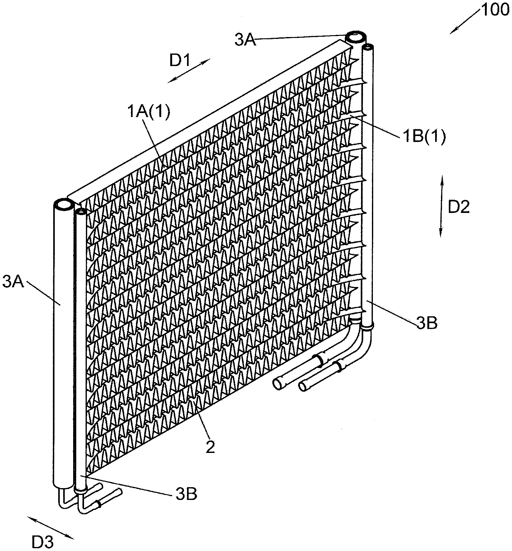
[0021] FIG. 1 is a schematic perspective view of a heat exchanger according to a first embodiment of the present invention;
[0022] FIG. 2 is a schematic top view of the heat exchanger according to the first embodiment of the present invention, in which flow directions of a refrigerant are indicated by arrows along heat exchange tubes;
[0023] FIG. 3 is a schematic top view of a heat exchanger according to a second embodiment of the present invention, in which flow directions of a refrigerant are indicated by arrows along heat exchange tubes;
[0024] FIG. 4 is a schematic partial enlarged view of a heat exchanger according to a third embodiment of the present invention;
[0025] FIG. 5 is a schematic partial enlarged view of a heat exchanger according to a fourth embodiment of the present invention;
[0026] FIG. 6 is a schematic perspective view of a heat exchanger according to a fifth embodiment of the present invention;
[0027] FIG. 7 is a schematic top view of the heat exchanger according to the fifth embodiment of the present invention;
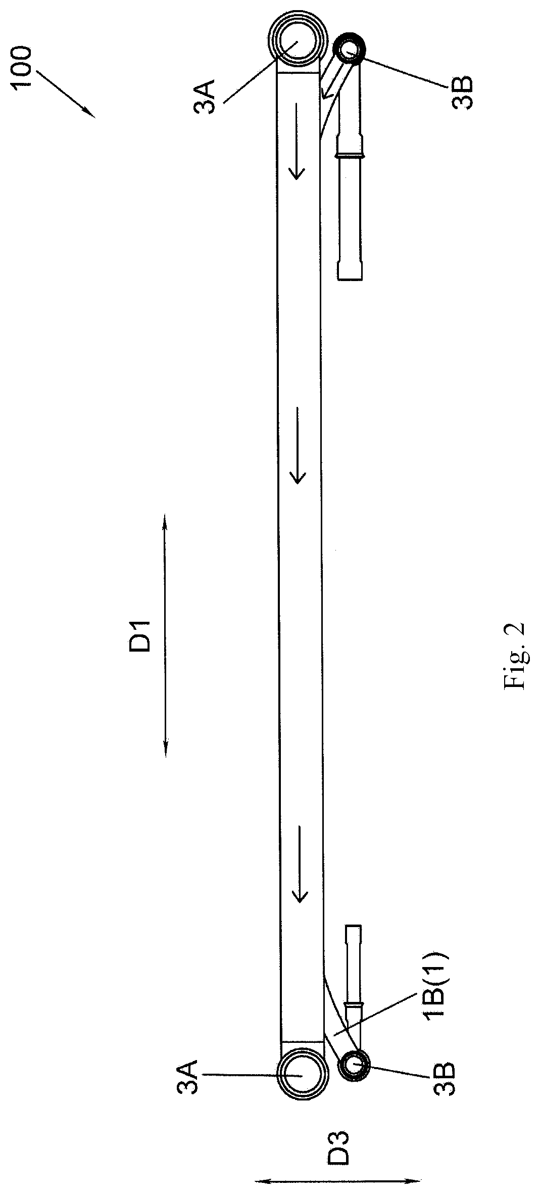
[0028] FIG. 8 is a schematic perspective view of a heat exchanger according to a sixth embodiment of the present invention;
[0029] FIG. 9 is a schematic top view of the heat exchanger according to the sixth embodiment of the present invention;
[0030] FIG. 10 is a schematic perspective view of a heat exchanger according to a seventh embodiment of the present invention; and
[0031] FIG. 11 is a schematic top view of the heat exchanger according to the seventh embodiment of the present invention.
DETAILED DESCRIPTION
[0032] An air-conditioning system according to embodiments of the present invention includes a heat exchanger. Specifically, the air-conditioning system according to the embodiments of the present invention includes a compressor, a heat exchanger as an evaporator, a heat exchanger as a condenser, an expansion valve, and the like. The air-conditioning system may include two or more circuits. Each circuit is constituted by a portion of a heat exchanger configured to form this circuit. A plurality of portions of the heat exchanger respectively configured to form the circuits are connected in parallel and are independent of one another.
[0033] Referring to FIGS. 1 to 11, a heat exchanger 100 according to embodiments of the present invention includes heat exchange tubes 1. The heat exchange tubes 1 include first heat exchange tubes 1A configured to form a first circuit, and second heat exchange tubes 1B configured to form a second circuit.
[0034] According to embodiments of the present invention, the first circuit and the second circuit may be two circuits connected in parallel and are independent of each other. The first circuit has a greater heat exchange capability than the second circuit. For example, the first heat exchange tubes 1A have a greater total heat exchange capability than the second heat exchange tubes 1B. Referring to FIGS. 1 to 4 and 6 to 11, the heat exchanger 100 according to the embodiments of the present invention further includes first fins 2, at least a portion of each of which extends in a first direction D1, which are arranged in a row in a second direction D2 perpendicular to the first direction D1, and which are arranged alternately with the heat exchange tubes 1. Thereby, for example, if one of two circuits of a two-circuit air-conditioning system is turned off, at least some of fins for the one circuit may be used for the other circuit to improve a heat exchange efficiency of the heat exchanger. In some examples of the present invention, the first heat exchange tubes 1A include a plurality of first heat exchange tube sets, the second heat exchange tubes 1B include a plurality of second heat exchange tube sets, and the plurality of first heat exchange tube sets and the plurality of second heat exchange tube sets are arranged alternately in the second direction D2. The plurality of first heat exchange tube sets may have the same number or different numbers of first heat exchange tubes 1A. The plurality of second heat exchange tube sets may have the same number or different numbers of second heat exchange tubes 1B.
[0035] Referring to FIGS. 1 to 11, in some embodiments of the present invention, a heat exchange capability between the first heat exchange tubes 1A and the fins is greater than a heat exchange capability between the second heat exchange tubes 1B and the fins. In the present embodiment, a heat exchange capability between the first heat exchange tubes 1A and the first fins 2 is greater than a heat exchange capability between the second heat exchange tubes 1B and the first fins 2. For example, the different heat exchange capabilities of the first heat exchange tubes 1A and the second heat exchange tubes 1B become advantageous when refrigerant circuits and associated compression systems have different sizes and capacities to allow for a capacity modulation and an unloading at different stages.
[0036] Referring to FIGS. 1 to 4, in some embodiments of the present invention, the first heat exchange tubes 1A and the second heat exchange tubes 1B are arranged alternately in the second direction D2. In other embodiments of the present invention, first heat exchange tube sets each composed of at least one (one, two, three or more) of the first heat exchange tubes 1A, and second heat exchange tube sets each composed of at least one (one, two, three or more) of the second heat exchange tubes 1B are arranged alternately in the second direction D2. In other words, a plurality of first heat exchange tube sets and a plurality of second heat exchange tube sets are arranged alternately. The heat exchange tube 1 may be a flat tube. A number of the first heat exchange tubes 1A is greater than a number of the second heat exchange tubes 1B, the first heat exchange tube 1A has a greater length than the second heat exchange tube 1B, the first heat exchange tube 1A has a greater width than the second heat exchange tube 1B, the first heat exchange tube 1A has a greater thickness than the second heat exchange tube 1B, and/or a total cross sectional area of internal channels of the first heat exchange tube 1A is greater than a total cross sectional area of internal channels of the second heat exchange tube 1B. According to examples of the present invention, the first heat exchange tubes 1A, the second heat exchange tubes 1B, and the first fins 2 are aligned, on at least one side in a third direction D3 perpendicular to both the first direction D1 and the second direction D2, with one another in the second direction D2.
[0037] Referring to FIGS. 6 to 11, in some embodiments of the present invention, the heat exchange tube 1 may be a flat tube. A number of the first heat exchange tubes 1A is greater than a number of the second heat exchange tubes 1B, the first heat exchange tube 1A has a greater width than the second heat exchange tube 1B, the first heat exchange tube 1A has a greater thickness than the second heat exchange tube 1B, and/or a total cross sectional area of internal channels of the first heat exchange tube 1A is greater than a total cross sectional area of internal channels of the second heat exchange tube 1B. According to examples of the present invention, the first heat exchange tubes 1A, the second heat exchange tubes 1B, and the first fins 2 are aligned, on at least one side in a third direction D3 perpendicular to both the first direction D1 and the second direction D2, with one another in the second direction D2.
[0038] Referring to FIGS. 1 to 4 and 6 to 11, in some embodiments of the present invention, the first fin 2 has a same size in the third direction D3 perpendicular to both the first direction D1 and the second direction D2 as a bigger one of a portion of the first heat exchange tube 1A in contact with the first fin 2 and a portion of the second heat exchange tube 1B in contact with the first fin 2. Thereby, both the first heat exchange tube 1A and the second heat exchange tube 1B are in contact with the first fin 2 over their entire sizes (for example their entire widths) in the third direction D3.
[0039] Referring to FIG. 5, in some embodiments of the present invention, the heat exchange tubes 1 are arranged in the second direction D2 such that a plurality of same repeating units 20 are arranged in the second direction D2, each of the repeating units 20 is composed of a predetermined number of heat exchange tubes 1, and in each of the repeating units 20, the first heat exchange tubes 1A and the second heat exchange tubes 1B are arranged alternately in the second direction D2. For example, each of the repeating units 20 is composed of three first heat exchange tubes 1A and two second heat exchange tubes 1B, and each of the two second heat exchange tubes 1B is located between two adjacent ones of the three first heat exchange tubes 1A; each of the repeating units 20 is composed of two first heat exchange tubes 1A and one second heat exchange tube 1B, and the one second heat exchange tube 1B is located between the two first heat exchange tubes 1A; or each of the repeating units 20 is composed of four first heat exchange tubes 1A and three second heat exchange tubes 1B, and each of the three second heat exchange tubes 1B is located between two adjacent ones of the four first heat exchange tubes 1A. The first heat exchange tube 1A and the second heat exchange tube 1B are heat exchange tubes of the same type. Alternatively, the first heat exchange tube 1A and the second heat exchange tube 1B may be heat exchange tubes of different types. In this way, for example, a ratio of the heat exchange capability between the first heat exchange tubes 1A and the first fins 2 to the heat exchange capability between the second heat exchange tubes 1B and the first fins 2 may be 2:1, 3:2, 4:3, or the like. In this way, a heat exchange capability of the first fins 2 can be utilized to the utmost extent, while achieving various ratios of the heat exchange capability between the first heat exchange tubes 1A and the first fins 2 to the heat exchange capability between the second heat exchange tubes 1B and the first fins 2.
[0040] Referring to FIG. 3, in some embodiments of the present invention, the first heat exchange tube 1A includes: a first heat exchange tube part 1A1 and a second heat exchange tube part 1A2 arranged in the third direction D3 perpendicular to both the first direction D1 and the second direction D2; and a connection part 1A3 connecting and fluidly communicating the first heat exchange tube part 1A1 and the second heat exchange tube part 1A2 with each other. The first heat exchange tube part 1A1 and the second heat exchange tube part 1A2 are in contact with a same first fin 2 located on one side of the first heat exchange tube part 1A1 and the second heat exchange tube part 1A2 in the second direction D2 and are in contact with a same first fin 2 located on the other side of the first heat exchange tube part 1A1 and the second heat exchange tube part 1A2 in the second direction D2. For example, the first heat exchange tube part 1A1, the second heat exchange tube part 1A2, and the connection part 1A3 of the first heat exchange tube 1A may be formed by bending a single heat exchange tube.
[0041] In the embodiment shown in FIG. 3, the heat exchanger 100 further includes: first fins 2, at least a portion of each of which extends in the first direction D1, and which are arranged in a row in the second direction D2 perpendicular to the first direction D1; and second fins, at least a portion of each of which extends in the first direction D1, and which are arranged in a row in the second direction D2 perpendicular to the first direction D1. The first heat exchange tube 1A includes: a first heat exchange tube part 1A1 and a second heat exchange tube part 1A2 arranged in the third direction D3 perpendicular to both the first direction D1 and the second direction D2; and a connection part 1A3 connecting and fluidly communicating the first heat exchange tube part 1A1 and the second heat exchange tube part 1A2 with each other. The first fins 2 and a first set of heat exchange tubes 1 composed of both the first heat exchange tube parts 1A1 and the second heat exchange tubes 1B are arranged alternately in a row in the second direction D2 perpendicular to the first direction D1, and the second fins and a second set of heat exchange tubes 1 composed of the second heat exchange tube parts 1A2 are arranged alternately in a row in the second direction D2 perpendicular to the first direction D1. A height of the second fin in the second direction D2 is substantially equal to a distance between two adjacent second heat exchange tube parts 1A2, and is greater than a height of the first fin 2 in the second direction D2. In other words, in the present embodiment, the first heat exchange tube 1A has a greater length than the second heat exchange tube 1B, thereby achieving different heat exchange capabilities of different circulation circuits. In addition to the achievement of the different heat exchange capabilities of the different circulation circuits, an installation space for the heat exchanger is sufficiently utilized. The heat exchanger is obviously superior in heat exchange capability to a single-row heat exchanger. The first heat exchange tube parts 1A1 and the second heat exchange tube parts 1A2 may be substantially parallel to one another, and may be substantially parallel to the second heat exchange tubes 1B.
[0042] Referring to FIGS. 1 to 3 and 6 to 11, in some embodiments of the present invention, the heat exchanger 100 further includes: first manifolds 3A respectively disposed at two ends of each of the first heat exchange tubes 1A; and second manifolds 3B respectively disposed at two ends of each of the second heat exchange tubes 1B.
[0043] According to embodiments of the present invention, referring to FIGS. 6 to 11, the heat exchanger 100 further includes: first fins 2, at least a portion of each of which extends in a first direction D1, which are arranged in a row in a second direction D2 perpendicular to the first direction D1, and which are arranged alternately with the heat exchange tubes 1. The heat exchanger 100 is bent in an L shape (FIGS. 6 and 7), a U shape (FIGS. 10 and 11), or a C shape (FIGS. 8 and 9) when viewed in the second direction D2 (i.e. when viewed in a top view). In addition, the heat exchanger 100 may be bent in any other shape such as a V shape.
[0044] According to the embodiments of the present invention, at least some of the plurality of first fins 2 are shared by the first heat exchange tubes 1A and the second heat exchange tubes 1B. Therefore, if one of two circuits of a two-circuit air-conditioning system is turned off, at least some of the first fins for the one circuit may be used for the other circuit to improve a heat exchange efficiency of the heat exchanger.
[0045] According to embodiments of the present invention, referring to FIGS. 1, 2 and 4, the first heat exchange tubes 1A and the second heat exchange tubes 1B are arranged alternately in the second direction D2. The heat exchange tube 1 is a flat tube, and the first heat exchange tube 1A has a greater width than the second heat exchange tube 1B. According to examples of the present invention, the first heat exchange tubes 1A, the second heat exchange tubes 1B, and the first fins 2 are aligned, on at least one side in a third direction D3 perpendicular to both the first direction D1 and the second direction D2, with one another in the second direction D2. If a flat tube having a small width which is easily bent is used, a manifold having a small diameter may be used, thereby greatly saving a cost. In addition, an existing flat tube may be used without needing a flat tube having a new specification. For example, a ratio of the width of the first heat exchange tube 1A to the width of the second heat exchange tube 1B is 2:1. Thereby, the ratio of the heat exchange capability between the first heat exchange tubes 1A and the first fins 2 to the heat exchange capability between the second heat exchange tubes 1B and the first fins 2 is 2:1.
[0046] According to the embodiments of the present invention, the heat exchange capacity of the heat exchanger in the part load condition is improved, the heat exchanger can maintain an enough flow rate of a refrigerant for returning an oil in the part load condition, and in the case where one circuit fails, the air-conditioning system can continue to operate through another circuit.
[0047] According to the embodiments of the present invention, the heat exchanger is more compact. In addition, the first heat exchange tubes 1A and the second heat exchange tubes 1B are arranged alternately to the utmost extent, while achieving heat exchange capabilities of two circulation circuits which are different in ratio.
[0048] In addition, the above embodiments of the present invention may be combined into new embodiments.
[0049] While the present disclosure has been illustrated and described with respect to a particular embodiment thereof, it should be appreciated by those of ordinary skill in the art that various modifications to this disclosure may be made without departing from the spirit and scope of the present disclosure.
* * * * *
D00000
D00001
D00002
D00003
D00004
D00005
D00006
D00007
D00008
XML
uspto.report is an independent third-party trademark research tool that is not affiliated, endorsed, or sponsored by the United States Patent and Trademark Office (USPTO) or any other governmental organization. The information provided by uspto.report is based on publicly available data at the time of writing and is intended for informational purposes only.
While we strive to provide accurate and up-to-date information, we do not guarantee the accuracy, completeness, reliability, or suitability of the information displayed on this site. The use of this site is at your own risk. Any reliance you place on such information is therefore strictly at your own risk.
All official trademark data, including owner information, should be verified by visiting the official USPTO website at www.uspto.gov. This site is not intended to replace professional legal advice and should not be used as a substitute for consulting with a legal professional who is knowledgeable about trademark law.