Compressor
RINALDI; Budi ; et al.
U.S. patent application number 16/608564 was filed with the patent office on 2020-06-18 for compressor. This patent application is currently assigned to Brose Fahrzeugteile GmbH & Co. Kommanditgesellschaft, Wurzburg. The applicant listed for this patent is Brose Fahrzeugteile GmbH & Co. Kommanditgesellschaft, Wurzburg. Invention is credited to Bjorn FAGERLI, Budi RINALDI.
| Application Number | 20200191146 16/608564 |
| Document ID | / |
| Family ID | 62044746 |
| Filed Date | 2020-06-18 |
| United States Patent Application | 20200191146 |
| Kind Code | A1 |
| RINALDI; Budi ; et al. | June 18, 2020 |
COMPRESSOR
Abstract
An electric-motor refrigerant compressor, for compressing a fluid, having a compressor housing having a housing bottom, and having a compressor part mounted in the compressor housing for conveying the fluid from a low pressure-side inlet to a high pressure-side outlet. The separating device is introduced into the housing bottom and has a cylindrical separating chamber which is connected to the outlet, and a separator which is arranged coaxially in said separating chamber for separating lubricant which is contained in the fluid, and a high pressure chamber of the compressor housing is coupled in flow terms by means of a passage duct to the separating chamber. The passage duct may be made in an intermediate wall between the high pressure chamber and the separating chamber in such a way that said passage duct opens into the separating chamber offset radially and on the outer side of the separator.
| Inventors: | RINALDI; Budi; (Frankfurt am Main, DE) ; FAGERLI; Bjorn; (Rosbach vor der Hohe, DE) | ||||||||||
| Applicant: |
|
||||||||||
|---|---|---|---|---|---|---|---|---|---|---|---|
| Assignee: | Brose Fahrzeugteile GmbH & Co.
Kommanditgesellschaft, Wurzburg Wurzburg DE |
||||||||||
| Family ID: | 62044746 | ||||||||||
| Appl. No.: | 16/608564 | ||||||||||
| Filed: | April 24, 2018 | ||||||||||
| PCT Filed: | April 24, 2018 | ||||||||||
| PCT NO: | PCT/EP2018/060426 | ||||||||||
| 371 Date: | October 25, 2019 |
| Current U.S. Class: | 1/1 |
| Current CPC Class: | F04C 29/026 20130101; F04C 29/028 20130101; F04C 18/0215 20130101; F04B 39/121 20130101; F04B 39/123 20130101; F04C 2240/30 20130101; F04C 2240/40 20130101; F04B 35/04 20130101; F04C 18/0253 20130101; F04B 39/16 20130101 |
| International Class: | F04C 18/02 20060101 F04C018/02; F04C 29/02 20060101 F04C029/02 |
Foreign Application Data
| Date | Code | Application Number |
|---|---|---|
| Apr 27, 2017 | DE | 10 2017 207 145.1 |
Claims
1. An electric-motor refrigerant compressor configured to compress a fluid comprising: a housing having a housing bottom; a compressor part mounted in the housing and configured to deliver the fluid from a low-pressure-side inlet to a high-pressure-side outlet; and a separating device inserted into the housing bottom, wherein the separating device includes a cylindrical separating chamber connected to the high-pressure-side outlet and a separator, wherein the separator is arranged coaxially in the separating chamber and configured to separate lubricant contained in the fluid from the fluid, wherein a high-pressure chamber of the housing is coupled in terms of flow to the separating chamber by a passage duct, wherein the passage duct is formed by an intermediate wall disposed between the high-pressure chamber and the separating chamber in such a way that the passage duct opens into the separating chamber in a manner offset radially with respect to a central center line of the separator, and wherein a clear width of the passage duct is less than or equal to a gap width of an annular gap formed between the separator and an inner wall of the separating chamber.
2. The electric-motor refrigerant compressor of claim 1, wherein the passage duct is positioned in such a way that the fluid flows into the separating chamber and tangentially to the separator.
3. The electric-motor refrigerant compressor of claim 1, wherein the passage duct is offset radially with respect to the central center line of the separator by an offset, wherein a sum of the offset and of the clear width of the passage duct is less than or equal to a radius of the separating chamber.
4. The electric-motor refrigerant compressor of claim 1, wherein the passage duct has an inner wall oriented parallel to an inflow direction of the fluid and/or perpendicularly to the housing bottom.
5. The electric-motor refrigerant compressor of claim 4, wherein the separating chamber is oriented radially with respect to the housing bottom, wherein the passage duct is elongated and extends in a radial direction.
6. The electric-motor refrigerant compressor of claim 1, wherein the passage duct is a slotted aperture in the intermediate wall.
7. The electric-motor refrigerant compressor of claim 6, wherein the slotted aperture has a substantially rectangular cross-sectional shape.
8. The electric-motor refrigerant compressor of claim 1, wherein the separating chamber is formed between an inner wall of the housing bottom and the high-pressure chamber and wherein the separating chamber projects at least partially into the high-pressure chamber.
9. The electric-motor refrigerant compressor of claim 1, wherein the housing bottom has an annular wall projecting axially beyond the separating chamber to form the high-pressure chamber, and wherein the passage duct is arranged within the annular wall so that the passage duct is radially offset from the center line of the separator towards the outlet.
10. The electric-motor refrigerant compressor of claim 9, wherein the compressor part lies along the annular wall.
11. An electric refrigerant compressor comprising: a housing including a housing bottom, an annular wall axially spaced apart from the housing bottom, and an intermediate wall extending from the annular wall, wherein the intermediate wall, the housing bottom, and the annular wall form a separating chamber; a compressor part disposed within the housing and configured to deliver a fluid from a low-pressure-side inlet to a high-pressure-side outlet, wherein the compressor part, the intermediate wall, and the annular wall form a high-pressure chamber; and a separator defining a center line and disposed in the separating chamber, wherein the intermediate wall defines a passage duct, and wherein the separator and passage duct are arranged relative to one another so that the passage duct is oblique to and radially spaced apart from the center line of the separator.
12. The electric refrigerant compressor of claim 11, wherein the passage duct includes a first inner wall, formed by the intermediate wall, and a second inner wall, formed by the annular wall, wherein the first inner wall is spaced apart from the second inner wall by a first distance, wherein an outer surface of the separator is spaced apart from the second inner wall by a second distance, wherein the first distance is less than or equal to the second distance.
13. The electric refrigerant compressor of claim 12, wherein the first inner wall is spaced apart from the center line of the separator by a third distance and wherein a radius of the separator chamber is a fourth distance, wherein a sum of the first distance and the third distance is less than or equal to the fourth distance.
14. The electric refrigerant compressor of claim 11, wherein the separating chamber extends at least partially into the high-pressure chamber.
15. An electric refrigerant compressor comprising: a housing including a housing bottom, an annular wall axially spaced apart from the housing bottom, and an intermediate wall extending from the annular wall, wherein the intermediate wall, the housing bottom, and the annular wall form a separating chamber; a compressor part disposed within the housing and configured to deliver a fluid from a low-pressure-side inlet to a high-pressure-side outlet, wherein the compressor part, the intermediate wall, and the annular wall form a high-pressure chamber; and a separator defining a center line and disposed in the separating chamber, wherein the intermediate wall defines a passage duct, and wherein the passage duct includes a first inner wall, formed by the intermediate wall, and a second inner wall, formed by the annular wall, wherein the first inner wall has a first length and the second inner wall has a second length, less than the first length.
16. The electric refrigerant compressor of claim 15, wherein the first inner wall is spaced apart from the second inner wall by a first distance, wherein an outer surface of the separator is spaced apart from the second inner wall by a second distance, wherein the first distance is less than or equal to the second distance.
17. The electric refrigerant compressor of claim 16, wherein the first inner wall is spaced apart from the center line of the separator by a third distance and wherein a radius of the separator chamber is a fourth distance, wherein a sum of the first distance and the third distance is less than or equal to the fourth distance.
18. The electric refrigerant compressor of claim 15, wherein the separating chamber extends between an outlet, formed by the bottom housing, and a lubricant reservoir, and wherein one end of the lubricant reservoir has a conical shape.
19. The electric refrigerant compressor of claim 15, wherein the passage duct is elongated and extends in a radial direction.
20. The electric refrigerant compressor of claim 19, wherein the passage duct has a rectangular cross-sectional shape.
Description
CROSS-REFERENCE TO RELATED APPLICATIONS
[0001] This application is the U.S. National Phase of PCT/EP2018/060426 filed Apr. 24, 2018, which claims priority to DE 10 2017 207 145.1 filed Apr. 27, 2017, the disclosures of which are hereby incorporated in their entirety by reference herein.
TECHNICAL FIELD
[0002] The present disclosure relates to a compressor including an electric motor for use in an air-conditioning unit of a motor vehicle.
BACKGROUND
[0003] In vehicles, it is normal practice to install an air-conditioning unit which can cool the vehicle interior in the manner of a compression-type refrigeration unit. Fundamentally, systems of this kind have a circuit which contains a refrigerant, e.g. R-134a (1,1,1,2-tetrafluoroethane) or R-774 (CO.sub.2). During operation, the refrigerant is compressed by a compressor, leading to an increase in the pressure and temperature of the refrigerant. In particular, the compressor is driven in by an electric motor.
SUMMARY
[0004] Positioned downstream of the (refrigerant) compressor in terms of flow is a condenser, which is in thermal contact with the surroundings of the vehicle. As a consequence, the temperature of the refrigerant is lowered in the condenser, and the refrigerant is then passed into an evaporator positioned downstream in terms of flow. In the evaporator, the refrigerant is expanded to the original pressure, as a result of which the temperature of the refrigerant falls further.
[0005] Positioned downstream of the evaporator in terms of flow is a further heat exchanger, which is in thermal contact with a blower line of the air-conditioning unit leading into the interior of the vehicle. In this situation, thermal energy is transferred from the thermally contacted component to the refrigerant, leading to cooling of the component and heating of the refrigerant. To close the circuit, the refrigerant is fed back to the compressor.
[0006] Arranged in series in the flow direction in the compressor of the circuit and, in the compressor, in the compressor housing, which has a housing bottom, there are a first low-pressure-side compressor element of a compressor part and a second high-pressure-side compressor element of the compressor part, the latter being mounted in a fixed manner, for compressing the fluid, as well as a high-pressure chamber and a separating device.
[0007] Within the compressor there is a lubricant, which mixes with a gaseous refrigerant during operation. The lubricant (oil) serves to reduce the friction which occurs during operation in the compressor between the first compressor element and the second, high-pressure-side compressor element, which is mounted in a fixed manner. Furthermore, the lubricant performs a sealing function, ensuring that any (refrigerant) leaks arising between the compressor elements are reduced to a very great extent or completely avoided, which increases the efficiency of the refrigerant compressor.
[0008] As an example, the refrigerant mixed with lubricant, after being compressed by the compressor part in the compressor, flows into a high-pressure chamber which, in turn, is coupled to the separating device by a passage duct. In the separating device, the oil is separated from the refrigerant, and the separated oil is thus or may thus be returned to the compressor via a valve and a lubricant duct, and the refrigerant is passed into the refrigerant circuit via an outlet of the separating device as far as possible without oil.
[0009] The separating device has a separating chamber connected to the outlet and, in the chamber, a coaxially arranged separator, with the result that an annular space is formed between the separator and an inner wall of the separating chamber. The passage duct of the separating device is embodied as a round hole, wherein the fluid flows from the high-pressure chamber into the annular space of the separating chamber via the passage duct. In this process, the fluid flows from the high-pressure chamber into the separating chamber through a flow cross section matched to the delivery volume which occurs during operation and is determined by the clear width of the passage duct. Since the cross-sectional area of the flow cross section must be matched to the delivery volume which occurs during operation, the fluid flow branches into two partial flows, which are guided in opposite directions of flow along the two sides of the separator. This entails unwanted eddy formation in the annular space between the separator and the chamber inner wall of the separating chamber.
[0010] One or more objects of the present disclosure may be to provide a compressor in which the fluid delivered flows through the separating chamber with as little eddy formation as possible.
[0011] The device according to one or more embodiments, a compressor for compressing a fluid, in particular a refrigerant, wherein the compressor is arranged between a heat exchanger and a condenser in terms of flow, in a refrigerant circuit of an air-conditioning system. Here, the compressor has the task of increasing the pressure of the fluid delivered. The compressor has a (compressor) housing having a housing bottom and a compressor part, mounted in the housing, for delivering the fluid from a low-pressure-side inlet to a high-pressure-side outlet.
[0012] Within the compressor part and in a drive, such as an electric-motor drive, of the compressor part there is a lubricant, which mixes with the gaseous refrigerant during operation. It serves to reduce friction in the compressor part and in the drive thereof and performs a sealing function in the compressor part in that it to a very great extent reduces or completely prevents leaks between a first low-pressure-side compressor element and a second, high-pressure-side compressor element, the latter being mounted in a fixed manner. The lubricant should be separated from the fluid before being passed into the refrigerant circuit. The oil separated off and collected in a (lubricant) reservoir can advantageously be returned to the compressor part via a valve and a lubricant passage, leading to improved lubrication of the compressor elements and reducing friction in the compressor part. A further advantage conferred by the separation of the lubricant from the fluid is improved heat transfer to the heat exchanger of the refrigerant circuit, which increases the efficiency of the air-conditioning unit (of the air-conditioning or air-conditioning unit system).
[0013] For this purpose, a separating device for separating off the lubricant contained in the fluid is inserted into the housing bottom, wherein the separating device has a cylindrical separating chamber that is connected to the outlet and has a separator, which is arranged coaxially in the separating chamber.
[0014] The fluid flows out of the compressor part into a high-pressure chamber of the compressor housing, the chamber being positioned downstream of the part in terms of flow. The high-pressure chamber is coupled to the separating device in terms of flow by a passage duct in a common intermediate wall of the separating chamber and the high-pressure chamber. Here, the passage duct is introduced in such a way that it opens in a manner offset radially with respect to the central center line of the separator, which is arranged coaxially in the separating chamber and is, in particular, cylindrical, this ensuring selective guidance of the flow along just one side of the separator.
[0015] In particular, the compressor is an electric-motor refrigerant compressor for an air-conditioning unit of a vehicle. In operation, the air-conditioning unit is used to cool an interior of the vehicle or to cool an energy storage device for driving an electric-motor-operated vehicle, for example.
[0016] The heat exchanger is in thermal contact with any energy cells of a high voltage energy storage device or with a blower line leading into the interior of the motor vehicle. In this case, transfer of thermal energy to the refrigerant takes place, leading to cooling of the component in contact with the heat exchanger and to heating of the refrigerant. The condenser may be used to adjust the temperature of the refrigerant to the ambient temperature or at least to lower the temperature of the refrigerant and may be in thermal contact with the surroundings.
[0017] The compressor part is appropriately embodied as a scroll compressor. This operates as a refrigerant compressor in the manner of a positive displacement pump, wherein an electric motor drives a moving scroll part eccentrically relative to a fixed scroll part and, in doing so, compresses a fluid. The scroll parts form the compressor elements of the compressor part and, in this case, are typically embodied as a nested pair of spirals or scrolls. In this case, one of the spirals is fixed in relation to the compressor housing and engages at least partially in a second spiral, which is driven in an orbiting manner by an electric motor. In this context, an orbiting movement should be taken to mean, in particular, an eccentric circular orbit in which the second spiral itself does not rotate about its own axis. Two substantially crescent-shaped refrigerant chambers, the volume of which is reduced (compressed) in the course of the movement, are thereby formed between the spirals during each orbiting movement. The refrigerant is discharged into the high-pressure chamber via an outlet in the fixed scroll part.
[0018] The lubricant is expediently a (lubricating) oil, wherein the term "oil" should not be interpreted restrictively as mineral oils. On the contrary, it is also possible to use fully synthetic or partially synthetic oils, e.g. silicone oils, or other oil-like fluids such as hydraulic fluid or cooling lubricants.
[0019] The separating device separates the lubricant from the fluid in the manner of a centrifugal separator (cyclone separator). The fluid flowing tangentially into the separating chamber is guided along the separator in a helical manner (in the manner of a cyclone) in the separating chamber, which is, in particular, cylindrical. During this process, centrifugal forces act as a separating mechanism on the mixture of refrigerant and lubricant. In one conceivable embodiment, the lubricant reservoir is partially closed by a cone to form an annular slot in order to avoid the take-up of particles of the already separated lubricant by the fluid flow.
[0020] In an expedient embodiment, the compressor housing, together with the housing bottom, and the separating chamber of the separating device are formed by a diecasting method. Production which is particularly economical with materials and inexpensive is thereby ensured.
[0021] In an expedient embodiment, the passage duct is introduced in such a way into the intermediate wall between the separating chamber and the high-pressure chamber that the fluid delivered flows into the separating chamber tangentially to the separator, thereby ensuring particularly suitable positioning of the passage duct. In this case, the fluid flows in at an angle of less than 90.degree. to the housing bottom, for example. It is also possible for the passage duct to be introduced into the intermediate wall in such a way that the inflow direction of the fluid is perpendicular to the housing bottom, as a result of which the flow direction of the fluid through the passage duct is substantially identical with the delivery direction of the fluid by the compressor part, and less eddying arises at the passage duct. In this context, the inflow direction should be taken to mean the direction tangential to the separator in which the fluid flows into the separating chamber.
[0022] The invention proceeds from the consideration that the unwanted eddy formation in the annular space between the separator and the chamber inner wall of the separating chamber can be reduced considerably if the flow of the fluid is guided selectively along only one side of the separator. For this purpose, the passage duct opening into the annular space should be positioned as far as possible in a manner offset fully azimuthally with respect to the diameter of the separator.
[0023] In one or more embodiments, the clear width of the passage duct exceeds the gap width of an annular gap formed between the separator and an inner wall of the separating chamber. In other words, the clear width of the passage duct is less than or equal to the gap width of the annular gap. As a result, the fluid flows particularly advantageously tangentially into the annular gap and is guided selectively along just one side of the separator, thereby considerably reducing eddy formation.
[0024] In a suitable embodiment, the passage duct has an inner wall, which is oriented tangentially to the inflow direction of the fluid into the annular gap. In other words, the inner wall of the passage duct is oriented parallel to the inflow direction of the fluid into the separating chamber, as an advantageous result of which less eddying occurs at the passage duct during inflow.
[0025] As one example, the cylindrical separating chamber extends radially with respect to the housing bottom of the compressor housing, which is appropriately of pot-type shape. Here, the passage duct is of elongate shape along this radial direction. The flow cross section, formed by the clear width of the passage duct, during the inflow of the fluid from the high-pressure chamber into the separating chamber is matched to the fluid delivery volume which occurs during operation.
[0026] Since the flow cross section, formed by the clear area of the passage duct, from the high-pressure chamber into the separating chamber should be matched to the delivery volume which occurs during operation, and the clear width of the passage duct may be less than or equal to the gap width of the gap formed between the separator and the inner wall of the separating chamber, the passage duct is consequently of elongate design along the central center line of the separating device.
[0027] To avoid unwanted eddy formation, the passage duct is offset radially with respect to the center line of the separating device or with respect to the center line of the separator. In this case, the offset, including the clear width of the passage duct, is advantageously less than or equal to the radius of the cylindrical separating chamber. As a result, the fluid flows tangentially into the gap formed between the separator and the inner wall of the separating chamber. As a consequence, the fluid is guided selectively on only one side of the separator along an eddy-free path. Branching off of a partial flow of the fluid, which would be guided along the separator in the opposite direction of circulation from the eddy-free path, would collide with the eddy-free path and would lead to the formation of eddies, is avoided.
[0028] It is particularly advantageous if the passage duct is a slotted aperture in the intermediate wall. In an expedient embodiment, the shape of the passage duct has a substantially rectangular cross-sectional shape. In one conceivable embodiment, the cross-sectional shape of the passage duct is elliptical or oval. Here, the shape of the passage duct is matched to the operational delivery rate in such a way that the clear width of the passage duct changes only along the axis of the separating chamber. In other words, the passage duct between the separating chamber and the high-pressure chamber is matched in such a way to the operationally required delivery volume of the refrigerant that the fluid delivered flows through the separating chamber with only slight eddy formation.
[0029] In an expedient development, the separating chamber is formed between an inner wall of the housing bottom, the wall facing the compressor part, and the high-pressure chamber, wherein the separating chamber projects at least partially axially into the high-pressure chamber. A particularly space-saving and material-saving embodiment is thereby formed.
[0030] In another embodiment, the housing bottom has an annular wall which projects axially beyond the separating chamber, forming an inner and an outer annular region. The passage duct from the high-pressure chamber into the separating chamber is arranged radially offset in the direction of the outlet in the inner annular region, with the result that the fluid flow is guided around the separator of the separating chamber in a particularly advantageous manner along a cyclone-type path. In particular, this ensures improved separation of the lubricant from the refrigerant.
[0031] Furthermore, it is appropriate if the compressor part rests on the annular wall. In this case, the high-pressure chamber is formed by the housing bottom, the annular wall and the compressor part. In particular, additional sealing elements of the high-pressure chamber are not required, which saves space and is particularly advantageous in terms of flow.
[0032] One or more advantages may be obtained by the present disclosure may be that the eddy formation of the fluid flow in the separating chamber is considerably reduced by virtue of the particularly suitable arrangement and embodiment of the passage duct, taking account of the required delivery volume. For example, the cross-sectional shape of the passage duct is here adapted in such a way that, for the purpose of advantageous inflow behavior, the clear width of the passage duct does not exceed the gap width of the annular space (annular gap) formed between the separating chamber and the separator and is advantageously of elongate design along the axis of the separating chamber.
[0033] As a consequence of the reduced eddy formation, the lubricant separates better from the refrigerant and is not carried into the refrigerant circuit, for which reason there is better heat transfer between the heat exchangers and the refrigerant in the refrigerant circuit. Furthermore, owing to the improved separation, the lubrication of the compressor part by the separated and returned lubricant is improved, resulting in reduced wear and thus a longer life of the compressor. Moreover, the efficiency of the compressor is improved.
BRIEF DESCRIPTION OF THE DRAWINGS
[0034] An illustrative embodiment of the invention is explained in greater detail below with reference to a drawing. In the drawing:
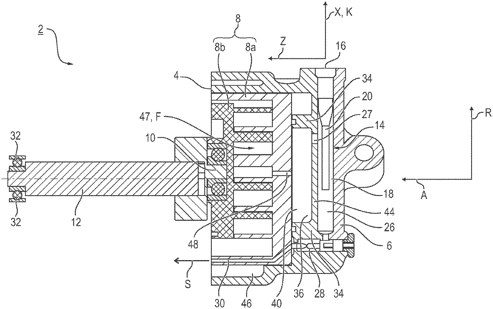
[0035] FIG. 1 shows a longitudinal section through a compressor having a housing and a compressor part and of a separating device on the housing bottom side,
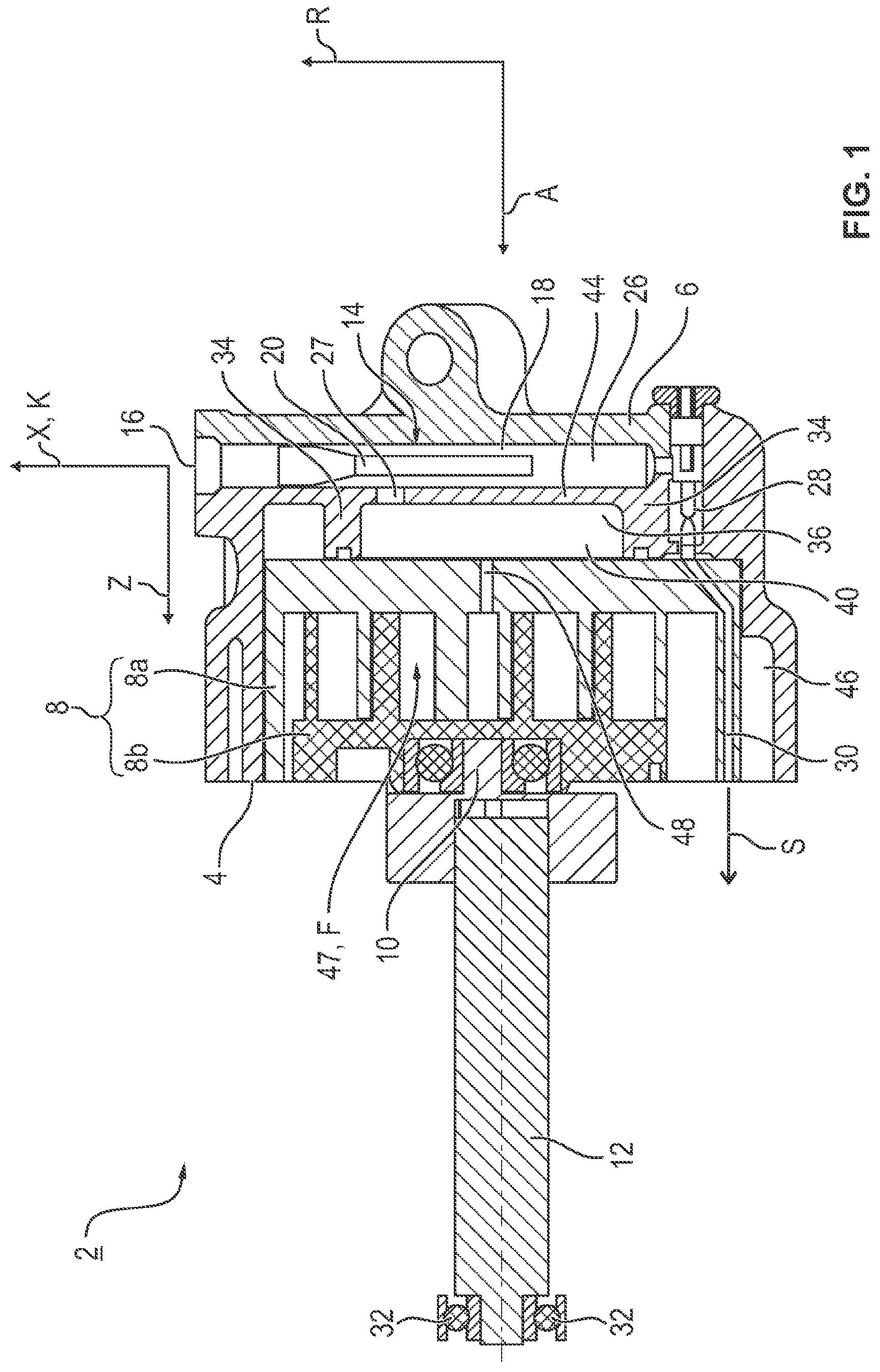
[0036] FIG. 2 shows the compressor housing in a plan view, viewed in the direction of the bottom-side separating device, with a passage duct of slotted cross-sectional shape,
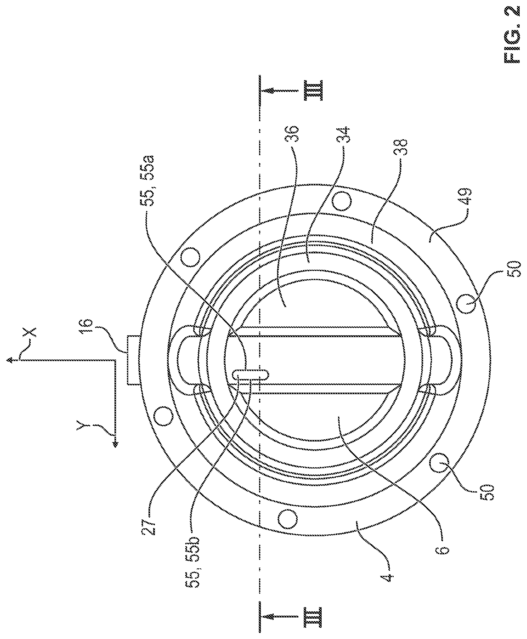
[0037] FIG. 3 shows the separating device and the flow path of a fluid through the passage duct and in the separating device in a sectional illustration along the line in FIG. 2, and
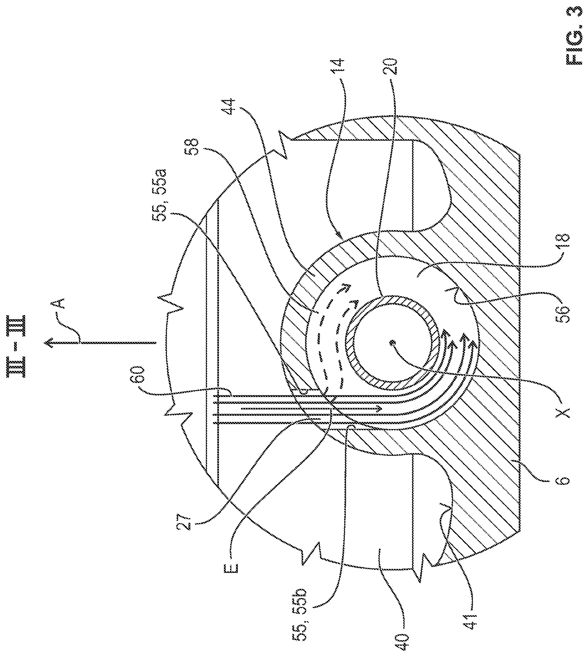
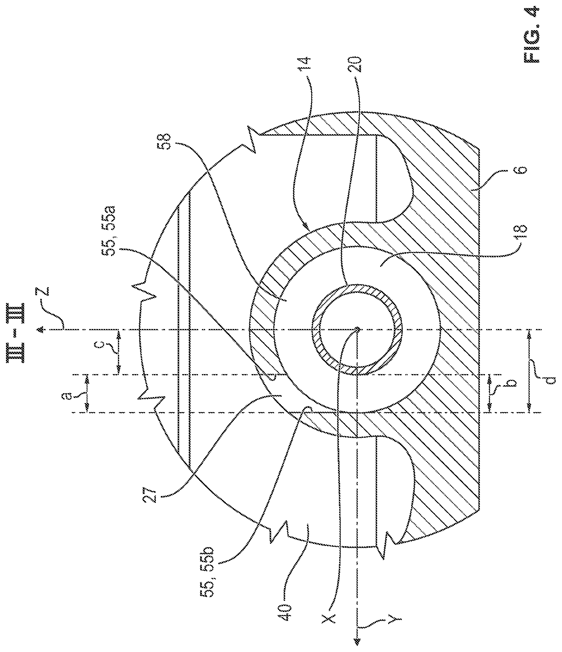
[0038] FIG. 4 shows the sectional illustration from FIG. 3 with a passage duct offset with respect to the center line of the separating device and without the flow path of the fluid in the separating device.
[0039] In all the figures, corresponding parts are in all cases provided with the same reference signs.
DETAILED DESCRIPTION
[0040] As required, detailed embodiments of the present invention are disclosed herein; however, it is to be understood that the disclosed embodiments are merely exemplary of the invention that may be embodied in various and alternative forms. The figures are not necessarily to scale; some features may be exaggerated or minimized to show details of particular components. Therefore, specific structural and functional details disclosed herein are not to be interpreted as limiting, but merely as a representative basis for teaching one skilled in the art to variously employ the present invention.
[0041] The compressor 2 illustrated in a sectional illustration in FIG. 1 for compressing a fluid F may be embodied as an electric-motor refrigerant compressor in a refrigerant circuit (not illustrated specifically) of an air-conditioning unit of a motor vehicle. The compressor 2 has a compressor housing 4 having a housing bottom 6 and a compressor part 8 mounted in the housing 4. The compressor part 8 has a first compressor element 8a, which is fixed relative to the compressor housing 4, and a moving second compressor element 8b, which engages therein and which is moved by shaft journals 10 and a motor shaft 12 by an electric motor (not illustrated specifically). Here, the compressor part 8 is embodied as a scroll compressor.
[0042] Within the compressor 2 there is a lubricant S, which is used to lubricate the compressor part 8 and performs a sealing function, thus avoiding leaks between the compressor elements 8a and 8b. Due to operating conditions, a refrigerant K and the lubricant S mix with the fluid F in this case.
[0043] The compressor housing 4 is embodied in the manner of a pot. The radial direction in relation to the compressor housing 4 and the axial direction perpendicular to the housing bottom 6 in the direction of the compressor part 8 are denoted in the adjacent direction diagram by R and A, respectively.
[0044] A separating device 14, which is connected to an outlet 16, is inserted into the housing bottom 6. The separating device 14 has a cylindrical separating chamber 18 and a hollow-cylindrical separator 20 arranged coaxially therein. The separating device 14 serves to separate the lubricant S contained in the fluid F into a lubricant reservoir 26 in the manner of a centrifugal separator. In the separating chamber 18, the fluid F flowing into the separating chamber 18 in an inflow direction E (FIG. 3) via a passage duct 27 flows around the separator 20 helically (in the manner of a cyclone) in the direction of the lubricant reservoir 26, wherein the centrifugal force acting on the refrigerant K contained in the fluid F and on the lubricant S contained in the fluid F acts as a separating mechanism. The refrigerant K separated from the lubricant S then flows out through the hollow-cylindrical separator 20 and the outlet 16 into the refrigerant circuit. In this context, the inflow direction E should be taken to mean the direction tangential to the separator 20 in which the fluid F flows into the separating chamber 18.
[0045] The separated lubricant S is fed back to the fixed compressor element 8b via a valve or restrictor 28 and via a lubricant duct 30. In this arrangement, the restrictor 26 is seated in the compressor housing 4. The returned lubricant S then flows via guide contours to rolling bearings 32 of the electric motor (not illustrated specifically) in order to lubricate and/or cool the bearings.
[0046] The axial direction of the separating device 14, i.e. the axial direction of the cylindrical separating chamber 18 and of the separator arranged coaxially therein, is denoted by X. The radial direction of the separating device 14 perpendicular to the inflow direction E and the radial direction of the separating device 14 parallel to the inflow direction E are denoted by Y and Z, respectively (FIG. 2).
[0047] Furthermore, the housing bottom 6 has an annular wall 34 projecting beyond the separating chamber 18. This divides the space surrounded by the fixed compressor part 8b and by the compressor housing 4 into an inner annular region 36 and into an outer annular region 38. A high-pressure chamber 40 is formed by the inner annular region 36, bounded by the housing bottom 6, the annular wall 34 and the compressor element 8b resting on the annular wall 34.
[0048] The separating chamber 18 is formed between an inner wall 41 of the housing bottom 6 and the high-pressure chamber 40, wherein the separating chamber 18 projects at least partially into the high-pressure chamber 40 in the axial direction A. The passage duct 27 couples the high-pressure chamber 40 to the separating chamber 18 in terms of flow. The passage duct 27 is introduced into an intermediate wall 44 between the separating chamber 18 and the high-pressure chamber 40 in such a way that the passage duct 27 opens into the separating chamber 18 in a manner offset along the radial direction Y of the separating device 14 with respect to the axial direction X of the separating device 14. In this case, the passage duct 27 is arranged in such a way in the inner annular region 36 of the annular wall 34 that the passage duct 27 is offset in the axial direction X of the separating device 14 or in the radial direction R of the compressor housing 4 toward the outlet.
[0049] On the low-pressure side of the compressor part 8, the fluid F flows into the compressor part 8 through an inlet 46. The compressor part 8, which in this case is a scroll compressor, compresses the fluid F in the manner of a positive displacement pump. The fluid F is compressed in a compressor part chamber 47 and then flows out of the compressor part 8 into the high-pressure chamber 40 through a high-pressure-side compressor part outlet 48.
[0050] FIG. 2 shows the pot-type compressor housing 4 with the compressor part 8 removed, looking at the housing bottom 6 of the compressor housing 4 along the axial direction A. The annular wall 34 projects beyond the separating device 14, forming the inner annular region 36 and the outer annular region 38. With the compressor part 8 (not illustrated in FIG. 2) and the housing bottom 6 of the compressor housing 4, the annular wall 34 forms the high-pressure chamber 40.
[0051] Furthermore, the compressor housing 4 has screw sockets 50 along a flange surface 49 to enable the compressor 2 to be fastened to a drive module (not illustrated), into which the motor of the compressor 2 is inserted. For the sake of greater clarity, only two screw sockets 50 are provided with a reference sign in FIG. 2.
[0052] The separating chamber 18 extends in the radial direction R with respect to the housing bottom 6 of the compressor housing 4. In this case, the passage duct 27 is offset in the radial direction R toward the outlet 16 of the separating chamber 18 in the inner annular region 36 and is of elongate shape along the axial direction X of the separating device 14. The passage duct 27 is embodied as a slotted aperture in the intermediate wall 44, wherein the aperture has a substantially rectangular cross-sectional shape. The cross-sectional shape of the passage duct 27 can be of slotted or oval design.
[0053] FIG. 3 shows the separating device 14 inserted into the housing bottom 6 of the compressor housing 4, looking toward the radially offset passage duct 27, in a sectional illustration along the line in FIG. 2. As is apparent, this passage is positioned in the intermediate wall 44 between the high-pressure chamber 40 and the separating chamber 18 in such a way that the fluid F delivered flows into the separating chamber 18 tangentially to the separator 20 in the inflow direction E.
[0054] In this case, the passage duct 27 has an inner wall 55, which is oriented tangentially to the inflow direction E of the fluid F in the passage duct 27. In this illustrative embodiment, the fluid F flows into the separating chamber 18 in such a way that both the inflow direction E and the inner wall 55 of the passage duct 27 are oriented perpendicularly to the housing bottom 6. That side of the inner wall 55 of the passage duct 27, the distance c (FIG. 4) of which from the radial direction or line Z, illustrated in dashed lines, of the separating device 14 parallel to the inflow direction E or, in this illustrative embodiment, perpendicular to the housing bottom 6 is shorter, is denoted by 55a (side closer to the axis). The opposite side of the inner wall 55 of the passage duct 27 is denoted by 55b (side remote from the axis).
[0055] The flow cross section, formed by the clear area of the passage duct 27, during the inflow of the fluid F from the high-pressure chamber 40 into the separating chamber 18 is matched to the operationally required fluid delivery volume. To avoid eddy formation of the flow of the fluid F in the separating chamber 18, the passage duct 27 is here matched to the operationally required delivery volume in such a way that the clear width a of the passage duct 27 may be smaller than the gap width b (a<b) of an annular gap 58 formed between the separator 20 and an inner wall 56 of the separating chamber 18. However, the clear width a can also be equal to the gap width b (a=b). Moreover, the passage duct 27 is of elongate shape along the axial direction X of the separating device 14. As a result, the fluid F flows tangentially into the annular gap 58 and is guided exclusively along one side of the separator 20, along an eddy-free path 60. Branching off of a second partial flow of the fluid F, indicated by the dashed arrows in FIG. 3, which would be guided along the separator 20 in the opposite direction of circulation from the eddy-free path 60 and would collide with the eddy-free path 60, is thereby avoided.
[0056] FIG. 4 shows, in the sectional illustration of FIG. 3, the separating device 14 inserted into the housing bottom 6, with the passage duct 27 having the clear width a and the gap formed by the inner wall 56 of the separating chamber 18 and the separator 20, having the gap width b.
[0057] To avoid unwanted eddy formation, the fluid F flows tangentially into the annular gap 58 formed between the separator 20 and the inner wall 56 of the separating chamber 18. As a consequence, the fluid F is guided selectively on only one side of the separator 20 along an eddy-free path 60 (FIG. 3). For this purpose, the passage duct 27 is in this illustrative embodiment offset along the radial direction Y of the separating device 14 relative to the center line X of the separating device 14 or relative to the center line X of the separator 20, wherein the offset c together with the clear width a of the passage duct 27 is less than or equal to the radius d of the separating chamber 18 or the inner wall 56 thereof, i.e. c+a.ltoreq.d. In other words, the offset c is the distance between the radial direction Z of the separating device 14 parallel to the inflow direction E and that side 55a of the inner wall 55 of the passage duct 27 which faces the central center line X.
[0058] The invention is not restricted to the illustrative embodiments described above. On the contrary, other variants of the invention can be derived therefrom by a person skilled in the art without exceeding the subject matter of the invention. In particular, all the individual features described in conjunction with the illustrative embodiments can furthermore also be combined in different ways without departing from the subject matter of the invention.
[0059] While exemplary embodiments are described above, it is not intended that these embodiments describe all possible forms of the invention. Rather, the words used in the specification are words of description rather than limitation, and it is understood that various changes may be made without departing from the spirit and scope of the invention. Additionally, the features of various implementing embodiments may be combined to form further embodiments of the invention.
LIST OF REFERENCE SIGNS
[0060] 2 compressor [0061] 4 compressor housing [0062] 6 housing bottom [0063] 8 compressor part [0064] 8a first compressor element [0065] 8b second compressor element [0066] 10 shaft journal [0067] 12 motor shaft [0068] 14 separating device [0069] 16 outlet [0070] 18 separating chamber [0071] 20 separator [0072] 26 lubricant reservoir [0073] 27 passage duct [0074] 28 restrictor [0075] 30 lubricant duct [0076] 32 rolling bearing [0077] 34 annular wall [0078] 36 inner annular region [0079] 38 outer annular region [0080] 40 high-pressure chamber [0081] 41 inner wall of the housing bottom [0082] 44 intermediate wall [0083] 46 inlet [0084] 47 compressor part chamber [0085] 48 compressor part outlet [0086] 49 flange surface [0087] 50 screw sockets [0088] 55 inner wall of the passage duct [0089] 55a side of the inner wall closer to the axis [0090] 55b side of the inner wall remote from the axis [0091] 56 inner wall of the separating chamber [0092] 58 annular gap [0093] 60 flow path of the fluid [0094] A axial direction of the compressor housing [0095] E inflow direction [0096] F fluid [0097] K refrigerant [0098] S lubricant [0099] M center line of the separator [0100] R radial direction of the compressor housing [0101] X axial direction/center line of the separating device [0102] Y radial direction of the separating device perpendicular to the inflow direction [0103] Z radial direction of the separating device parallel to the inflow direction [0104] a clear width [0105] b gap width [0106] c distance/offset [0107] d radius of the inner wall of the separating chamber
* * * * *
D00000
D00001
D00002
D00003
D00004
XML
uspto.report is an independent third-party trademark research tool that is not affiliated, endorsed, or sponsored by the United States Patent and Trademark Office (USPTO) or any other governmental organization. The information provided by uspto.report is based on publicly available data at the time of writing and is intended for informational purposes only.
While we strive to provide accurate and up-to-date information, we do not guarantee the accuracy, completeness, reliability, or suitability of the information displayed on this site. The use of this site is at your own risk. Any reliance you place on such information is therefore strictly at your own risk.
All official trademark data, including owner information, should be verified by visiting the official USPTO website at www.uspto.gov. This site is not intended to replace professional legal advice and should not be used as a substitute for consulting with a legal professional who is knowledgeable about trademark law.