Prefabricated Frame
Wong; Conrad Tin Cheung ; et al.
U.S. patent application number 16/455418 was filed with the patent office on 2020-06-18 for prefabricated frame. This patent application is currently assigned to Yau Lee Wah Construction Materials (Huizhou) Company Limited. The applicant listed for this patent is Yau Lee Wah Construction Materials (Huizhou) Company Limited. Invention is credited to Conrad Tin Cheung Wong, Rosana Wai Man Wong.
| Application Number | 20200190799 16/455418 |
| Document ID | / |
| Family ID | 65459988 |
| Filed Date | 2020-06-18 |


| United States Patent Application | 20200190799 |
| Kind Code | A1 |
| Wong; Conrad Tin Cheung ; et al. | June 18, 2020 |
PREFABRICATED FRAME
Abstract
Disclosed herewith a prefabricated frame, including a column (1), a main beam (2), a secondary beam (3), and a floor (5). The main beam (2) and the secondary beam (3) are both prefabricated members, and provided with exposed reserve reinforcing bars. The floor (5) is a laminated plate having a prefabricated slab (51) at a lower portion thereof. The prefabricated slab (51), the main beam (2), and the secondary beam (3) are connected together through in-situ casting concrete on respective top portions thereof. The column (1) is a prefabricated column, which has exposed reserve reinforcing bars at a top thereof, and a to-be-cast structure at a bottom thereof for connection with a lower building structure, which has exposed reinforcing bars inserted into the to-be-cast structure. The connection between the column (1) and the lower building structure is achieved by casting in-situ concrete in the to-be-cast structure (12).
| Inventors: | Wong; Conrad Tin Cheung; (Shenzhen, CN) ; Wong; Rosana Wai Man; (Shenzhen, CN) | ||||||||||
| Applicant: |
|
||||||||||
|---|---|---|---|---|---|---|---|---|---|---|---|
| Assignee: | Yau Lee Wah Construction Materials
(Huizhou) Company Limited Huizhou City CN |
||||||||||
| Family ID: | 65459988 | ||||||||||
| Appl. No.: | 16/455418 | ||||||||||
| Filed: | June 27, 2019 |
| Current U.S. Class: | 1/1 |
| Current CPC Class: | E04B 5/38 20130101; E04B 1/20 20130101; E04B 5/43 20130101; E04B 1/2403 20130101; E04B 1/30 20130101; E04G 21/14 20130101; E04B 1/19 20130101; E04B 2001/1918 20130101; E04C 3/34 20130101; E04C 1/24 20130101; E04B 2/7425 20130101 |
| International Class: | E04B 5/00 20060101 E04B005/00; E04B 1/20 20060101 E04B001/20; E04B 1/19 20060101 E04B001/19; E04C 3/34 20060101 E04C003/34; E04B 1/30 20060101 E04B001/30; E04G 21/14 20060101 E04G021/14 |
Foreign Application Data
| Date | Code | Application Number |
|---|---|---|
| Dec 18, 2018 | CN | 201811551493.2 |
Claims
1. A prefabricated frame, comprising at least one column (1), at least one main beam (2) connected to the column (1), at least one secondary beam (3) connected to the main beam (2), and a floor (5), wherein the column (1), the main beam (2) and the secondary beam (3) are all prefabricated members, and the main beam (2) and the secondary beam (3) are both provided with, on respective top portions thereof, exposed reserve reinforcing bars, and reinforcing bars for cast-in-situ parts, wherein the floor (5) is a laminated plate having a prefabricated slab (51) at a lower portion thereof, and the prefabricated slab (51), the main beam (2), and the secondary beam (3) are connected together by means of in-situ casting concrete on respective top portions thereof, wherein the column (1) is a prefabricated column having exposed reserve reinforcing bars (11) at a top thereof and a to-be-cast structure (12) at a bottom thereof, the to-be-cast structure (12) being provided therein with reserve connecting bars, and wherein the to-be-cast structure (12) is used for connection with a lower building structure, which has exposed reinforcing bars that are located under the column and inserted into the to-be-cast structure (12), a connection between the column (1) and the lower building structure being achieved by casting in-situ concrete in the to-be-cast structure (12).
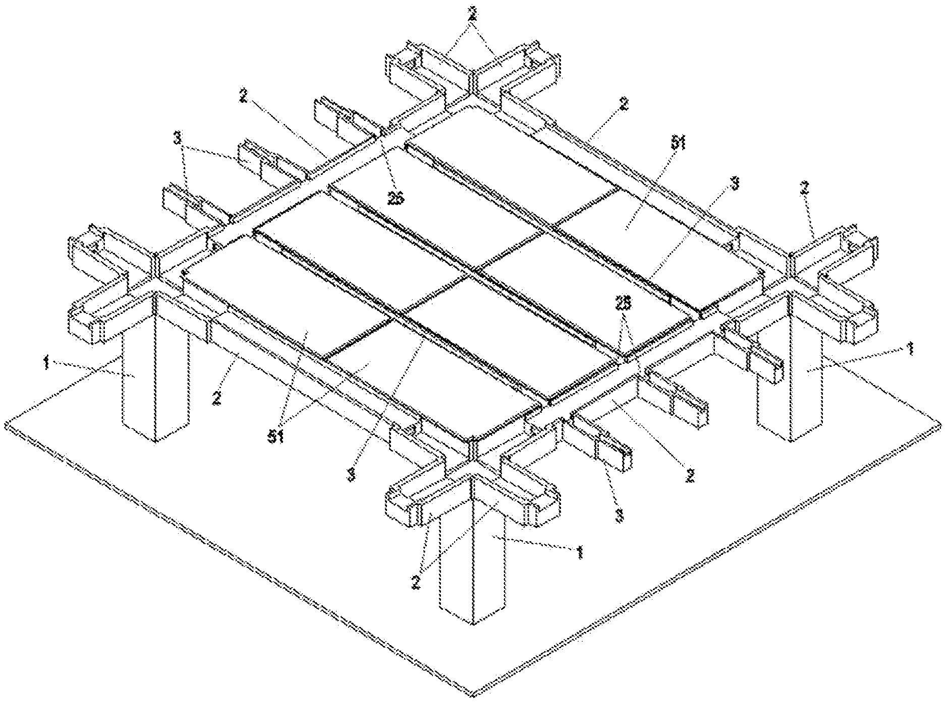
2. The prefabricated frame according to claim 1, wherein the column (1) is recessed inwardly at one or more lower sidewalls thereof to form the to-be-cast structure (12).
3. The prefabricated frame according to claim 2, wherein the exposed reinforcing bars of the lower building structure are overlapped and bundled with the reserve connecting bars of the to-be-cast structure (12), so that the column (1) and the lower building structure are connected with each other through establishing a template outside of the to-be-cast structure (12) and pouring concrete therewith.
4. The prefabricated frame according to claim 1, wherein the to-be-cast structure (12) includes a plurality of sleeves embedded in a bottom of the column (1), each sleeve being provided with a grouting passage and a slurry discharging passage, both passages having respective openings exposed on a sidewall of the column (1), and the reserve connecting bars of the to-be-cast structure (12) are vertical reinforcing bars, which are inserted into the sleeves from upper opening ends of the sleeves.
5. The prefabricated frame according to claim 4, wherein the grouting passage and the slurry discharging passage are arranged at a lower end and an upper end of the sleeve, respectively.
6. The prefabricated frame according to claim 4, wherein the exposed reinforcing bars of the lower building structure are inserted into the sleeves from lower opening ends of the sleeves, and the column (1) is integrally connected with the lower building structure by pouring concrete into the sleeves through the grouting passage, with excessive concrete being discharged from the slurry discharging passage.
7. The prefabricated frame according to claim 1, wherein the exposed reserve reinforcing bars on the top of the column (1) are higher than the main beam (2) and the floor (5).
8. The prefabricated frame according to claim 1, wherein at a connection node between the main beam (2) and a column (1) located at one end of the frame, the cast-in-situ portion at one end of the main beam (2) is provided with upper and lower connecting bars, each of the connecting bars being bent at a free end thereof
9. The prefabricated frame according to claim 1, wherein at connection nodes between the column (1) and two main beams (2) to a right side and to a left side thereof, the cast-in-situ parts at one end of one of said two main beams (2) is provided with upper and lower connecting bars, which pass above the column (1) and extend to the other of said two main beams (2), and both ends of the upper connecting bars are connected to reinforcing bars arranged on top of the cast-in-situ parts of said two main beams (2), respectively.
10. The prefabricated frame according to claim 1, wherein a cement mortar layer is disposed between a bottom surface of the column (1) and the lower building structure.
Description
TECHNICAL FIELD
[0001] The invention relates to a building structure, in particular to a novel prefabricated frame, which is particularly suitable for all buildings with frame structures or frame-shear wall structures.
TECHNICAL BACKGROUND
[0002] A conventional frame structure building, established through assembling prefabricated members, mainly uses prefabricated members such as prefabricated secondary beams, prefabricated slabs, or the like. During construction, a column should be cast in-situ first, followed by mounting of the prefabricated secondary beam and the prefabricated slab, and then in-situ casting of main beam reinforcing bars. Finally, concrete is cast in-situ on the prefabricated slab, so as to connect the main beam, the prefabricated secondary beam, and the prefabricated slab together. The use of prefabricated members can reduce on-site construction work, save labors, and improve construction efficiency.
[0003] However, the prefabricated members used in the existing building structures are limited, and a large number of structures still need to be formed by cast-in-situ concrete. Therefore, the amount of on-site construction workload is still heavy, and the construction period cannot be further shortened.
SUMMARY OF THE INVENTION
[0004] The technical problem to be solved by the present invention is to provide a prefabricated frame, in which the prefabricated members account for a large proportion of all structural members used, thus significantly reducing the amount of on-site construction work.
[0005] The present invention proposes a prefabricated frame, comprising at least one column, at least one main beam connected to the column, at least one secondary beam connected to the main beam, and a floor. The column, the main beam and the secondary beam are all prefabricated members, and the main beam and the secondary beam are both provided with, on respective top portions thereof, exposed reserve reinforcing bars, and reinforcing bars for cast-in-situ parts. The floor is a laminated plate having a prefabricated slab at a lower portion thereof, and the prefabricated slab, the main beam, and the secondary beam are connected together by means of in-situ casting concrete on respective top portions thereof. The column is a prefabricated column having exposed reserve reinforcing bars at a top thereof and a to-be-cast structure at a bottom thereof, the to-be-cast structure being provided therein with reserve connecting bars. The to-be-cast structure is used for connection with a lower building structure, which has exposed reinforcing bars that are located under the column and inserted into the to-be-cast structure, the connection between the column and the lower building structure being achieved by casting in-situ concrete in the to-be-cast structure.
[0006] In a first implementing embodiment, the column is recessed inwardly at one or more lower sidewalls thereof to form the to-be-cast structure.
[0007] In the first implementing embodiment, optionally, the exposed reinforcing bars of the lower building structure are overlapped and bundled with the reserve connecting bars of the to-be-cast structure, so that the column and the lower building structure are connected with each other through establishing a template outside of the to-be-cast structure and pouring concrete therewith.
[0008] In a second implementing embodiment, the to-be-cast structure includes a plurality of sleeves embedded in a bottom of the column, each sleeve being provided with a grouting passage and a slurry discharging passage, both passages having respective openings on a sidewall of the column, and the reserve connecting bars of the to-be-cast structure are vertical reinforcing bars, which are inserted into the sleeves from upper opening ends of the sleeves.
[0009] In the second implementing embodiment, optionally, the grouting passage and the slurry discharging passage are arranged at a lower end and an upper end of the sleeve, respectively.
[0010] In the second implementing embodiment, optionally, the exposed reinforcing bars of the lower building structure are inserted into the sleeves from lower opening ends of the sleeves, and the column is integrally connected with the lower building structure by pouring concrete into the sleeves through the grouting passage, with excessive concrete being discharged from the slurry discharging passage.
[0011] Optionally, the exposed reserve reinforcing bars on the top of the column are higher than the main beam and the floor.
[0012] Optionally, at a connection node between the main beam and a column located at one end of the frame, the cast-in-situ portion at one end of the main beam is provided with upper and lower connecting bars, each of the connecting bars being bent at a free end thereof.
[0013] Optionally, at connection nodes between the column and two main beams to a right side and to a left side thereof, the cast-in-situ parts at one end of one of said two main beams is provided with upper and lower connecting bars, which pass above the column and extend to the other of said two main beams, and both ends of the upper connecting bars are connected to reinforcing bars arranged on top of the cast-in-situ parts of said two main beams, respectively.
[0014] Optionally, a cement mortar layer is disposed between a bottom surface of the column and the lower building structure.
[0015] Compared with the prior arts, the novel prefabricated frame according to the present invention has the following advantages.
[0016] First, the conventional cast-in-situ main beam is replaced with the prefabricated main beam, and the reinforcing bars for cast-in-situ parts of the prefabricated main beam and the prefabricated secondary beam have been prepared in advance and fixed on the prefabricated members. This will save a lot of construction work on site, and reduce investment in the human resources for on-site reinforcement breaking and reinforcement fixing.
[0017] Second, the column is a prefabricated column having exposed reserve reinforcing bars at a top thereof and a to-be-cast structure at a bottom thereof, the to-be-cast structure being used for connection with a lower building structure. With the prefabricated column, the construction can be performed more rapidly and conveniently, and the construction quality can be consistently ensured. Therefore, the on-site workload can be significantly reduced, thus greatly shortening the construction duration. Moreover, construction can be performed in the middle area and in the side areas of the building in parallel, thus reducing labor cost, construction waste, and noise and sand pollution. In this manner, the influence of the construction on surrounding residents can be avoided to a maximum extent.
[0018] Third, construction progress can be accelerated, thereby improving construction efficiency and shortening an overall project duration.
[0019] Fourth, as a result of increase in factory production of the prefabricated members, the quality of products can be more effectively guaranteed. And as the prefabricated members can be favorably completed, on-site polishing and secondary repair procedures can be directly saved.
[0020] Finally, the column, the main beam, the secondary beam, and the floor are all in the form of prefabricated members, which can reduce the use of a large number of wood plate molds. Only a few gaps between members are necessary to be blocked with plate molds. This also remarkably reduces construction waste on site, and thus is more environmentally friendly.
BRIEF DESCRIPTION OF THE DRAWINGS
[0021] FIG. 1 schematically shows the structure of a novel prefabricated frame of the present invention;
[0022] FIG. 2 schematically shows a main structural diagram of a prefabricated main beam according to Embodiment 1 thereof, wherein its exposed reserve reinforcing bars are not shown;
[0023] FIG. 3 schematically shows a main structural diagram of the prefabricated main beam according to Embodiment 2 thereof, wherein its exposed reserve reinforcing bars are not shown;
[0024] FIG. 4 schematically shows a main structural diagram of a prefabricated secondary beam according to Embodiment 1 thereof, wherein its exposed reserve reinforcing bars are not shown;
[0025] FIG. 5 schematically shows a main structural diagram of the prefabricated secondary beam according to Embodiment 2 thereof, wherein its exposed reserve reinforcing bars are not shown;
[0026] FIG. 6 schematically shows a temporary support for the main beam, the secondary beam, and a prefabricated slab during construction;
[0027] FIG. 7 is a detail view showing an end node at a junction between a cast-in-situ column and the main beam;
[0028] FIG. 8 is a detail view showing a central node at a junction between the cast-in-situ column and each of the main beams located at right and left sides of the column; and
[0029] FIG. 9 is a detail view showing a node at a junction between the main beam and each of the secondary beams located at left and right sides of the main beam.
[0030] FIGS. 10 to 12 schematically show a main structural diagram of a column according to a first example; and
[0031] FIGS. 13 to 15 schematically show a main structural diagram of a column according to a second example.
DETAILED DESCRIPTION OF THE INVENTION
[0032] The present invention will be described in further detail with reference to preferred embodiments shown in the accompanying drawings.
[0033] As shown in FIGS. 1 and 6, a novel prefabricated frame according to the present invention includes at least one column 1, at least one main beam 2 connected to the column 1, at least one secondary beam 3 connected to the main beam 2, and a floor 5. The present invention is characterized in that the column 1, the main beam 2 and the secondary beam 3 are all prefabricated members, and the floor 5 is a laminated plate, wherein a lower part of the floor 5 is a prefabricated slab 51 while an upper part thereof is a cast-in-situ concrete layer 52. The main beam 2, the secondary beam 3, and the prefabricated slab 51 are all provided with exposed reserve reinforcing bars at respective top portions thereof, and provided in advance with reinforcing bars for cast-in-situ parts, all the reinforcing bars being temporarily fixed. During construction, after the prefabricated main beam, the prefabricated secondary beam, and the floor are mounted through hoist, the reinforcing bars for cast-in-situ parts that are arranged in recesses are pulled or inserted into their respective designated positions, bundled in series, and then fixed. The reinforcing bars for cast-in-situ parts are connected to the exposed reserve reinforcing bars of the prefabricated members. The prefabricated slab 51, the prefabricated main beam 2, and the prefabricated secondary beam 3 are used as a bottom mold, and connected together through in-situ casting concrete on the bottom mold. In addition, the column 1 is a prefabricated column having exposed reserve reinforcing bars at a top thereof and a to-be-cast structure at a bottom thereof. The to-be-cast structure is provided therein with reserve connecting bars for connection with a lower building structure. Exposed reinforcing bars of the lower building structure, which are located under the column, are inserted into the to-be-cast structure. The connection between the column 1 and the lower building structure is achieved through in-situ casting concrete in the to-be-cast structure.
[0034] According to the present invention, the main beam 2 may be configured in either of the following two structural modes.
[0035] In Embodiment 1 of the main beam 2 as shown in FIG. 2, the width of the main beam 2 at two end portions 22 thereof is larger than that at a middle portion 21 thereof, so that the middle portion 21 is connected to each of the end portions 22 through a step part. The middle portion 21 and the two end portions 22 of the main beam 2 are provided, on their top portions, with recesses 23 and 24, respectively, wherein the recess 23 of the middle portion 21 is relatively shallow, and the recesses 24 of the end portions 22 are relatively deep and open to respective end faces of the main beam 2. Two sides of the middle portion 21 and two sides of each of the end portions 22 are equally high. Concrete, while being cast in-situ on the floor, is also cast in-situ in the recesses 23 and 24 on the top portion of the main beam 2, thus forming the cast-in-situ parts of the main beam 2.
[0036] Embodiment 2 of the main beam 2 as shown in FIG. 3 differs from Embodiment 1 of the main beam 2 in that, in said Embodiment 2,the width of the two end portions 22 is equal to the width of the middle portion 21 of the main beam 2, whereas the height of the two sides of the end portions 22 is much lower than the height of the two sides of the middle portion 21. Therefore, a small amount of templates are necessary to block both sides of the end portions 22 during on-site construction.
[0037] Similarly, in the present invention, the secondary beam 3 may also be configured in either of the following two structural modes.
[0038] In Embodiment 1 of the secondary beam 3 as shown in FIG. 4, the width at two end portions 32 of the secondary beam 3 is larger than that at a middle portion 31 of the secondary beam 3, so that the middle portion 31 is connected to each of the end portions 32 through a step part. The middle portion 31 and the two end portions 32 of the secondary beam 3 are provided, on their top portions, with recesses 33 and 34, respectively, wherein the recess 33 of the middle portion 31 is relatively shallow, and the recesses 34 of the end portions 32 are relatively deep and open to end faces of the secondary beam 3. Two sides of the middle portion 31 and two sides of the end portions 32 are equally high. Concrete, while being cast in-situ on the floor, is also cast in-situ in the recesses 33 and 34 on the top portions of the secondary beam 3, thus forming the cast-in-situ parts of the secondary beam 3.
[0039] Embodiment 2 of the secondary beam 3 as shown in FIG. 5 differs from Embodiment 1 of the secondary beam 3 in that, in said Embodiment 2, the width of the two end portions 32 is equal to the width of the middle portion 31 of the secondary beam 3, whereas the height of the two sides of the end portions 32 is much lower than the height of the two sides of the middle portion 31. Therefore, a small amount of templates are necessary to block both sides of the end portions 32 during on-site construction.
[0040] Main reinforcing bars for cast-in-situ parts of the main beam 2 and the secondary beam 3 can be respectively provided in advance in the recesses 23 and 24 at the top portion of the main beam 2, and in the recesses 31 and 34 at the top portion of the secondary beam 3, and then transported together with the prefabricated members to the construction site. After the main beam 2 and the secondary beam 3 are mounted through hoist, the above main reinforcing bars are separately pulled or inserted into corresponding positions, bundled in series, and then fixed.
[0041] As shown in FIG. 1, the main beam 2 is mounted between two adjacent columns 1, and the end portions of the main beam 2 are disposed on top edges of the columns 1 in a specific floor. The secondary beam 3 is mounted between two adjacent main beams 2. The end faces of the secondary beam 3 abut against sidewalls of the main beams 2. At a position where the sidewall of the main beam 2 connects the secondary beam 3 is provided with an opening 25, so that the reinforcing bars at the top portion of the secondary beam 3 can conveniently pass therethrough.
[0042] As shown in FIG. 9, a reinforcing bar connector 78 is provided in advance at a lower position of a junction between the main beam 2 and each of the secondary beams 3 located at left and right sides of the main beam 2, and is connected to a reinforcing bar 77 provided in a prefabricated part of the main beam 2. Before concrete is cast in-situ, a reinforcing bar 93 provided in the recess 34 at the end portion of the secondary beam 3 is connected to a corresponding reinforcing bar connector 78, thereby achieving connection between the reinforcing bar 77 provided in the prefabricated part of the main beam 2 and the reinforcing bar 93 for the cast-in-situ part at the end portion of the secondary beam 3. And a connecting bar 79 is provided at a top portion of the cast-in-situ part at the end portion of the secondary beam 3 located at one side of the main beam 2, passes along a bottom portion of a reinforcing bar provided at the top portion of the main beam 2, and extends to the secondary beam 3 located at the other side of the main beam 2. Two ends of the connecting bar 79 partially overlap reinforcing bars 92 provided at the top portions of the cast-in-situ parts of the left and right secondary beams 3, respectively. The end portions of the secondary beams 3 are provided with exposed reserve stirrups 94, which extend from the prefabricated parts of the secondary beams 3. These stirrups 94 connect reinforcing bars 91 provided in the prefabricated part of the secondary beam 3 with the reinforcing bars 92 and 79 provided at the cast-in-situ part of the secondary beam 3, and enclose them. The reinforcing bars 93, 79, and 92 may be arranged in the recesses of the secondary beams 3 at a prefabrication factory in advance, then directly pulled or inserted, after the main beams and secondary beams are mounted at the construction site, into corresponding positions, bundled in series, and then fixed.
[0043] As shown in FIG. 7, at a connecting node between the main beam 2 and an end column 1, connecting bars 74 and 73 are respectively provided at an upper portion and a lower portion of the cast-in-situ part at the end portion of the main beam 2. The lower connecting bar 73 has one end extending into the column 1 connected thereto and being bent upwardly. The upper connecting bar 74 has one end extending similarly into the column 1 connected thereto and being bent downwardly, and another end partially overlapping a reinforcing bar 72 provided at a cast-in-situ concrete part at an upper portion of the main beam 2. The end portion of the main beam 2 is provided with exposed reserve stirrups 75, which extend from the prefabricated part of the main beam 2. These stirrups 75 connect the reinforcing bar 71 provided in the prefabricated part of the main beam 2 with the reinforcing bars 74 and 72 provided at the cast-in-situ part of the main beam 2, and enclose them. The reinforcing bars 72, 73, and 74 may be arranged in the recesses of the main beam 2 at a prefabrication factory in advance, and directly pulled or inserted, after the main beam 2 is mounted at the construction site, into the corresponding positions, bundled in series, and then fixed.
[0044] As shown in FIG. 8, at connecting nodes between the column 1 and the main beams 2 located at left and right sides of the column 1, connecting bars 81 and 82 are respectively provided at upper and lower positions of the cast-in-situ part at the end portion of the main beam 2 located at one side of the column 1, pass through the column 1, and extend to the main beam 2 located at the other side of the column 1. Two ends of the upper connecting 81 partially overlap the reinforcing bars 72 provided at the top portions of the cast-in-situ parts of the left and right main beams 2, respectively. The end portions of each of the main beams 2 located at both sides of the column 1 are provided with exposed reserve stirrups 76, which extend from the prefabricated part thereof These stirrups 76 connect the reinforcing bars 71 provided in the prefabricated parts of the main beams 2 with the reinforcing bars 72 and 81 provided in the cast-in-situ parts thereof, and enclose them. The reinforcing bars 72, 81, and 82 may be arranged in the recesses of the main beam 2 at a prefabrication factory in advance, and directly pulled or inserted, after the main beam 2 is mounted at the construction site, into the corresponding positions, bundled in series, and then fixed.
[0045] FIGS. 10-15 schematically show the structure of the column 1 according to examples of the present invention.
[0046] According to the present invention, the column 1 may be configured in either of the following two structural modes.
[0047] In a first example, as shown in FIG. 10, the column 1 of this example is a prefabricated column having a reinforced concrete structure made by one-piece prefabrication, comprising prefabricated concrete and reinforcing bars arranged therein.
[0048] The reinforcing bars inside the column 1 may be exposed to a certain length from the top of the column 1. The exposed portions, referred to as exposed reinforcing bars 11, are used for connection with an upper building structure.
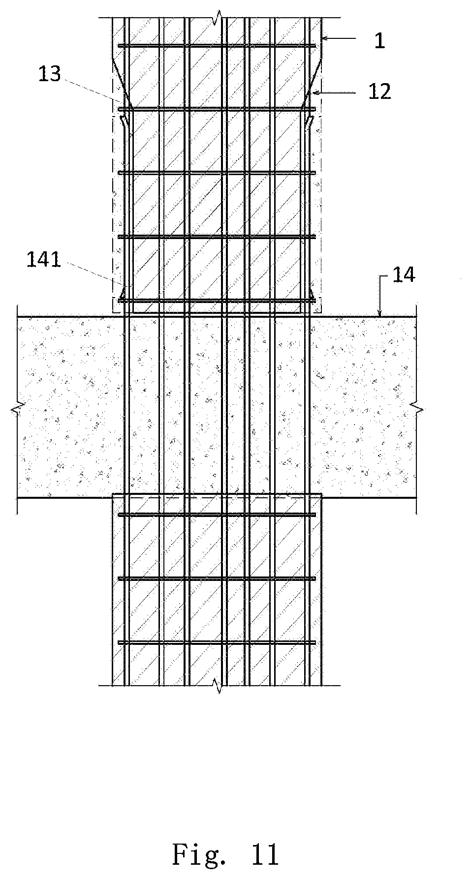
[0049] The bottom of the column 1 is provided with a to-be-cast structure 12, which is provided therein with reserve connecting bars 13. Optionally, the sidewalls of the column 1 are inwardly recessed at the lower end thereof, so that the recessed portion forms the to-be-cast structure 12. The recessed portion may be formed such that four sidewalls of the column 1 are all recessed inwardly to a certain depth at a region of the lower end of the column 1, or only part of them is recessed inwardly to a certain depth. The depth of the recessed portion is preferably selected to expose the reinforcing bars inside the column 1. The exposed reinforcing bars in the to-be-cast structure 12 are called as reserve connecting bars, for connection with a lower building structure. The to-be-cast structure 12 can be cast in-situ with concrete, so as to achieve the connection to the lower building structure.
[0050] In order to increase the bonding force between the prefabricated concrete and the in-situ-cast concrete, in a preferred embodiment, the inner wall of the to-be-cast structure 12 is beveled, thus increasing the contact area between the prefabricated concrete and the in-situ-cast concrete. In this manner, the bonding force therebetween can be further improved.
[0051] The use of this to-be-cast structure facilitates the pouring of concrete and the integrated production of the prefabricated column at the factory, improves the overall prefabrication rate, and thus is advantageous for production and transportation.
[0052] Optionally, the reserve connecting bars 13 in the to-be-cast structure 12 include vertical reinforcing bars 131 and transverse stirrups 132. The vertical reinforcing bars 131 and the exposed reserve reinforcing bars 11 may be formed by exposed ends of the reinforcing bars inside the column 1, respectively.
[0053] Referring to FIG. 11, when the column 1 is installed on the lower building structure 14, the exposed reinforcing bars 141 on the top of the lower building structure 14 are inserted into the to-be-cast structure 12, which is poured with concrete to achieve the connection between the column 1 and the lower building structure 14.
[0054] Optionally, before the concrete is poured, the reserve connecting bars 13 in the to-be-cast structure 12 are firstly connected with the exposed reinforcing bars 141 on the top of the lower building structure 14, and fixed therewith by stirrups. Then, a template is established at the to-be-cast structure 12 and concrete is poured, thus connecting the prefabricated column with the lower building structure 14.
[0055] Optionally, before the column 1 is installed on the lower building structure 14, a cement mortar layer may be disposed between a bottom surface of the column 1 and a top surface of the lower building structure 14, thus realizing a close connection between the column 1 and the lower building structure 14.
[0056] Referring to FIG. 12, when the upper building structure 15 is formed or mounted on the column 1, the exposed reserve reinforcing bars 11 on the top of the column 1 are inserted into the upper building structure 15, with top ends thereof being exposed from the top of the upper building structure 15. The exposed portions of the reinforcing bars 11 are used as exposed reinforcing bars 151 at the top of the upper building structure 15. In this manner, a firm connection between the prefabricated column and the building structures can be achieved.
[0057] In addition, optionally, one or more sidewalls of the column 1 may be provided in advance with a decorative surface layer, so as to reduce the workload of subsequent on-site construction.
[0058] As described above, the member to be cast at the bottom of the prefabricated column can be formed as a toothed joint. The top and bottom of the prefabricated column are both provided with exposed reinforcing bars. The top of a lower prefabricated column can be formed into one piece with the cast-in-situ beam. In addition, the exposed steel bars at the top of the lower prefabricated column can be connected with the reserve connecting bars at the bottom of the upper prefabricated column, tied together by wires, and then fixed by stirrups. The upper and lower prefabricated columns can be connected with each other into one piece by establishing a template on the outer part of the prefabricated columns and then casting concrete therewith.
[0059] In a second example as shown in FIG. 13, the column 1 of said example is a prefabricated column having a reinforced concrete structure made by one-piece prefabrication, comprising prefabricated concrete and reinforcing bars arranged therein.
[0060] The reinforcing bars inside the column 1 may be exposed to a certain length from the top of the column 1. The exposed portions, referred to as exposed reinforcing bars 11, are used for connection with other building structures, such as a cast-in-situ beam. The bottom of the column 1 is provided with a to-be-cast structure 12, which is provided therein with reserve connecting bars 13.
[0061] Optionally, the to-be-cast structure 12 consists of a plurality of hollow sleeves 16 embedded at the bottom of the column 1. The reserve connection bars 13 are vertical reinforcing bars, which are inserted into the sleeves 16 from the upper opening ends thereof. The lower end of the interior of the sleeve 16 is empty, for insertion of other building elements, such as exposed reinforcing bars on top of a cast-in-situ beam. The sleeve 16 is provided with a grouting passage 161 and a slurry discharging passage 162. The openings of the grouting passage 161 and the slurry discharging passage 162 are respectively exposed on the sidewall of the column 1.
[0062] Referring to FIG. 14, when the column 1 is installed on the lower building structure 14, the exposed reinforcing bars 141 on the top of the lower building structure 14 are inserted into the sleeves 16 from the lower opening ends thereof.
[0063] The column 1 can be integrally connected with the lower building structure 14 by pouring concrete into the sleeve 16 through the grout passage 161. Excessive concrete can be discharged from the slurry discharging passage 162.
[0064] Optionally, in order to ensure that the sleeve 16 can be completely filled with concrete and to avoid generation of bubbles, the grouting passage 161 is provided at the lower end of the sleeve 16, and the slurry discharging passage 162 is provided at the upper end thereof.
[0065] Optionally, before the column 1 is installed on the lower building structure 14, a cement mortar layer may be disposed between the bottom surface of the column 1 and the top surface of the lower building structure 14, thus realizing close connection between the column 1 and the lower building structure 14.
[0066] Referring to FIG. 15, when the upper building structure 15 is formed or mounted on the column 1, the exposed reserve reinforcing bars 11 on the top of the column 1 are inserted into the upper building structure 15, with top ends thereof being exposed from the top of the upper building structure 15. The exposed portions of the reinforcing bars 11 are used as exposed reinforcing bars 151 at the top of the upper building structure 15. In this manner, a firm connection between the prefabricated column and the building structure can be achieved.
[0067] In addition, optionally, one or more sidewalls of the column 1 may be provided in advance with a decorative surface layer, so as to reduce the workload of subsequent on-site construction.
[0068] As described above, the to-be-cast structure of the prefabricated column is provided with sleeves for connection at the bottom thereof. The prefabricated column is provided with exposed reinforcing bars on the top thereof, and can be formed into one piece with the cast-in-situ beam. In addition, the exposed steel bars at the top of the lower prefabricated column can be inserted into the sleeves of the upper prefabricated column. The upper and lower prefabricated columns can be connected with each other into one piece by pouring concrete in the sleeves.
[0069] According to the novel prefabricated frame of the present invention, the prefabricated column, the prefabricated main beam, the prefabricated secondary beam, and the prefabricated floor slab are used, thereby remarkably reducing the amount of construction work on site, reducing pollution and waste, and saving labor forces significantly. Thus the construction efficiency can be effectively improved, and the duration can thus be shortened.
[0070] The foregoing is merely preferred embodiments of the present invention, but is not intended to be limitation of the present invention. It will be apparent to those skilled in the art that various changes and modifications can be made to the present invention. Any modifications, equivalent substitutions, improvements, and the like within the spirit and principles of the present invention are intended to be included within the scope of the present invention.
* * * * *
D00000
D00001
D00002
D00003
D00004
D00005
D00006
D00007
D00008
D00009
D00010
XML
uspto.report is an independent third-party trademark research tool that is not affiliated, endorsed, or sponsored by the United States Patent and Trademark Office (USPTO) or any other governmental organization. The information provided by uspto.report is based on publicly available data at the time of writing and is intended for informational purposes only.
While we strive to provide accurate and up-to-date information, we do not guarantee the accuracy, completeness, reliability, or suitability of the information displayed on this site. The use of this site is at your own risk. Any reliance you place on such information is therefore strictly at your own risk.
All official trademark data, including owner information, should be verified by visiting the official USPTO website at www.uspto.gov. This site is not intended to replace professional legal advice and should not be used as a substitute for consulting with a legal professional who is knowledgeable about trademark law.