Novel Graphene Ternary Composite Direct Current-carrying Plate
WANG; Shuangfei ; et al.
U.S. patent application number 16/265284 was filed with the patent office on 2020-06-18 for novel graphene ternary composite direct current-carrying plate. This patent application is currently assigned to GuangXi University. The applicant listed for this patent is GuangXi University. Invention is credited to ZHAN LEI, Chen LIANG, Xinliang LIU, Yang LIU, Shuangxi NIE, Chengrong QIN, Shuangfei WANG, Zhiwei WANG, Shuangquan YAO.
| Application Number | 20200190676 16/265284 |
| Document ID | / |
| Family ID | 65962579 |
| Filed Date | 2020-06-18 |
| United States Patent Application | 20200190676 |
| Kind Code | A1 |
| WANG; Shuangfei ; et al. | June 18, 2020 |
NOVEL GRAPHENE TERNARY COMPOSITE DIRECT CURRENT-CARRYING PLATE
Abstract
A graphene ternary composite direct current-carrying plate includes an anode plate and a cathode plate. Placed between the anode plate and the cathode plate is a graphene composite layer. The graphene composite layer is doped with a certain proportion of graphene in the aluminum mesh frame. The plate of the invention has small thickness, low ohmic voltage drop, good porosity, and low current loss. This reduces the electrolysis power consumption, thereby significantly reducing the product cost and effectively promoting the industrial production market of the sodium chlorate electrolysis method. The plate also reduces energy consumption and is environmentally friendly.
| Inventors: | WANG; Shuangfei; (Nanning, CN) ; LIU; Yang; (Nanning, CN) ; QIN; Chengrong; (Nanning, CN) ; LEI; ZHAN; (Nanning, CN) ; NIE; Shuangxi; (Nanning, CN) ; YAO; Shuangquan; (Nanning, CN) ; LIANG; Chen; (Nanning, CN) ; LIU; Xinliang; (Nanning, CN) ; WANG; Zhiwei; (Nanning, CN) | ||||||||||
| Applicant: |
|
||||||||||
|---|---|---|---|---|---|---|---|---|---|---|---|
| Assignee: | GuangXi University |
||||||||||
| Family ID: | 65962579 | ||||||||||
| Appl. No.: | 16/265284 | ||||||||||
| Filed: | February 1, 2019 |
| Current U.S. Class: | 1/1 |
| Current CPC Class: | C25B 9/08 20130101; C25B 1/265 20130101; C25B 9/04 20130101; C25B 13/04 20130101; C25B 13/02 20130101 |
| International Class: | C25B 9/08 20060101 C25B009/08; C25B 13/02 20060101 C25B013/02; C25B 1/26 20060101 C25B001/26; C25B 13/04 20060101 C25B013/04 |
Foreign Application Data
| Date | Code | Application Number |
|---|---|---|
| Dec 14, 2018 | CN | 201811536160.2 |
Claims
1. A graphene ternary composite direct current-carrying plate, comprising: an anode plate and a cathode plate; and a graphene composite layer placed between the anode plate and the cathode plate, wherein the graphene composite layer comprises an aluminum mesh frame, and a certain proportion of the aluminum mesh frame is doped with graphene.
2. The graphene ternary composite direct current-carrying plate according to claim 1, wherein the aluminum mesh frame of the graphene composite layer is rhombic, square, circular or elliptical.
3. The graphene ternary composite direct current-carrying plate according to claim 1, wherein the graphene accounts for no more than 10 percent by mass of the graphene composite layer.
4. The graphene ternary composite direct current-carrying plate according to claim 1, wherein the direct current-carrying plate composed of the anode plate, the graphite composite layer, and the cathode plate has a thickness of 12-25 mm.
5. The graphene ternary composite direct current-carrying plate according to claim 1, wherein the graphene composite layer has a thickness of 3-5 mm.
6. The graphene ternary composite direct current-carrying plate according to claim 1, wherein the anode plate is a titanium substrate ternary coating with a thickness of 1-5 mm;
7. The graphene ternary composite direct current-carrying plate according to claim 1, wherein the cathode plate is a thin steel plate having a thickness of 8-15 mm.
Description
CROSS-REFERENCE TO RELATED APPLICATION
[0001] This application claims the benefit of Chinese Patent Application No. 201811536160.2, filed on Dec. 14, 2018. The subject matter thereof is hereby incorporated herein by reference in its entirety.
FIELD
[0002] The present invention relates to a direct current-carrying plate, and in particular, to a graphene ternary composite direct current-carrying plate and application thereof.
BACKGROUND
[0003] Sodium chlorate electrolysis is produced by electrolyzing industrial brine and is the main industrial production method. This method consumes a large amount of electricity, and also consumes about 5,500 kW and h/t in the electrolysis process. Furthermore, the power consumption accounts for about 60% of the product cost.
[0004] The electricity consumption for the production of sodium chlorate depends on the level of the electrolyzer, the choice of cell type and the advancement of electrolysis technology. The current-carrying plate is an important part of the electrolysis cell. The traditional bus-bar connection electrolysis technology uses bolts or bus bars to connect the copper bars and aluminum rows. The current loss of this technology is large, and there is a short circuit of the electrolytic cells. This short circuit seriously affects the normal operation of the equipment.
[0005] Nowadays, the direct current-carrying technology of the baffle is used. This technique requires good conductivity and mechanical strength of the baffle. The baffle needs to have a certain porosity and lower ohmic voltage drop.
[0006] However, a graphene ternary composite direct current-carrying plate, which may have a small thickness, a reduced ohmic voltage, a good porosity and a small current loss, may be beneficial.
SUMMARY
[0007] Certain embodiments of the present invention may provide solutions to the problems and needs in the art that have not yet been fully identified, appreciated, or solved by current current-carrying plate technology. Some embodiments generally pertain to a graphene ternary composite direct current-carrying plate, which may have a small thickness, a reduced ohmic voltage, a good porosity and a small current loss.
[0008] In one embodiment, a graphene ternary composite direct current-carrying plate includes an anode plate and a cathode plate. Graphene ternary composite direct current-carrying plate also includes a graphene composite layer placed between the anode plate and the cathode plate. The graphene composite layer includes an aluminum mesh frame, with a certain proportion of the aluminum mesh frame being doped with graphene.
BRIEF DESCRIPTION OF THE DRAWINGS
[0009] In order that the advantages of certain embodiments of the invention will be readily understood, a more particular description of the invention briefly described above will be rendered by reference to specific embodiments that are illustrated in the appended drawings. While it should be understood that these drawings depict only typical embodiments of the invention and are not therefore to be considered to be limiting of its scope, the invention will be described and explained with additional specificity and detail through the use of the accompanying drawings, in which:
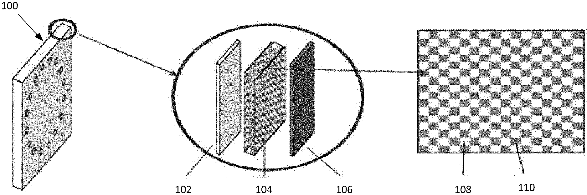
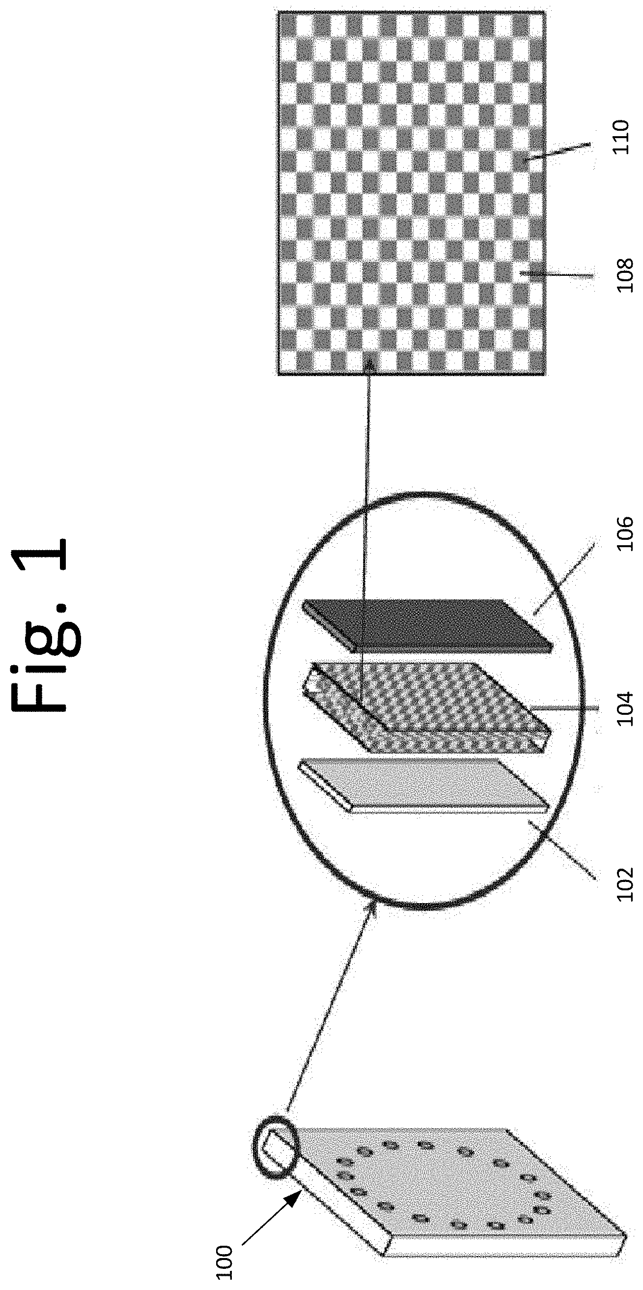
[0010] FIG. 1 is a structural view illustrating a graphene ternary composite direct current-carrying plate, according to an embodiment of the present invention.
DETAILED DESCRIPTION OF THE EMBODIMENTS
[0011] FIG. 1 is a structural view illustrating a graphene ternary composite direct current-carrying plate 100, according to an embodiment of the present invention.
[0012] In an embodiment, graphene ternary composite direct current-carrying plate (hereinafter "plate") 100 is composed of an anode plate 102, a graphene composite layer 104, and a cathode plate 106. In certain embodiments, anode plate 102 is composed of titanium and cathode plate 106 is a steel plate.
[0013] Graphene composite layer 104 is disposed between anode plate 102 and cathode plate 106. In an embodiment, graphene composite layer 102 includes an aluminum mesh frame 108. Certain proportion of aluminum mesh frame 108 is doped with graphene 110. Graphene 110 may have high electron mobility, carrier transport efficiency and current density.
[0014] The screen frame structure (aluminum mesh frame 108) of graphene composite layer 104 is a circular pore network aluminum layer structure, in some embodiments. Certain proportions of the screen frame structure incorporate graphene 110. In some embodiments, graphene 110 accounts for 5 percent by mass of the composite layer.
[0015] Plate 100 may have a thickness of 20 mm, in some embodiments. For example, graphene composite layer 104 may have a thickness of 3 mm. Anode plate 102, which includes a titanium matrix ternary coating, may have a thickness of 3 mm. Cathode plate 106, which includes a thin steel plate, may have a thickness of 14 mm.
[0016] In another embodiment, plate 100 may include anode plate 102, graphene composite layer 104, and a cathode plate 106. Graphene composite layer 104 is disposed between anode plate 102 and cathode plate 106. In some embodiments, graphene composite layer 104 includes an aluminum mesh frame 108. Certain proportion of aluminum mesh frame 108 may be doped with graphene 110. Graphene 110 may have high electron mobility, carrier transport efficiency and current density.
[0017] In certain embodiments, anode plate 102 is a titanium plate, and cathode plate 106 is a steel plate. Graphene composite layer 104 may include a screen frame structure. The screen frame structure includes a circular pore network aluminum layer structure, in some embodiments. A certain proportion of graphene may be incorporated in the composite layer of the screen frame structure, with graphene 110 accounting for 3 percent by mass of the composite layer.
[0018] Plate 100 in some embodiments may have a thickness of 16 mm. In an embodiment, graphene composite layer 104 has a thickness of 2 mm. Anode plate 102, which is a titanium matrix ternary coating, may have a thickness of 2 mm. Cathode plate 106, which is a thin steel plate, may have a thickness of 12 mm.
[0019] The electrolysis power consumption and the electrolysis efficiency of the graphene ternary composite direct current-carrying plate obtained in the above embodiments were measured and the results are shown in table 1.
TABLE-US-00001 TABLE 1 Determination of Electrolytic Performance of Novel Graphene Ternary Composite Direct Current-Loading Plate of the Invention Electrolysis power Electrolysis Scheme consumption (kW h/t) efficiency (%) Scheme 1 4960 97 Scheme 2 5100 95
[0020] As shown in Table 1, the electrolysis power consumption of the graphene ternary composite direct current-carrying plate is above 4960 kW, h/t. Also, in these embodiments, the electrolysis efficiency is above 95 percent, something that the conventional technology cannot achieve.
[0021] Some embodiments of the present invention generally pertain to a graphene ternary composite direct current-carrying plate that includes a titanium plate and a graphene composite layer placed between the anode plate and the cathode plate. The graphene composite layer is doped with a certain proportion of graphene in the aluminum mesh frame structure. The graphene ternary composite direct current-carrying plate also includes a steel plate.
[0022] In an embodiment, the anode plate is a titanium plate, and the cathode plate is a steel plate.
[0023] In some embodiments, the screen frame structure of the graphene composite layer is rhombic, square, circular or elliptical.
[0024] In certain embodiments, the graphene accounts for no more than 10% by mass of the graphene composite layer.
[0025] In one embodiment, the direct current-carrying plate has a thickness of 12-25 mm. In some other embodiments, the graphene composite layer has a thickness of 3-5 mm.
[0026] In some additional embodiments, the titanium plate is a titanium matrix ternary coating having a thickness of 1-5 mm, and the steel plate is a thin steel plate having a thickness of 8-15 mm.
[0027] One or embodiment embodiments described herein may have the following benefits:
[0028] In an embodiment, a direct current carrying technology of the deflector is adopted, and a deflector may be required to have good chemical stability and mechanical strength. The deflector may have a certain porosity and have a low ohmic voltage drop.
[0029] In view of the above requirements, the graphene ternary composite direct current-carrying plate, which adopts a titanium matrix ternary coating and a thin steel plate to achieve high chemical stability and mechanical strength of the deflector, may include a graphene composite layer with an aluminum mesh structure. Certain portions of the aluminum mesh structure may include graphene. Graphene, which has good porosity and mechanical strength, significantly reduces the thickness of the deflector.
[0030] The graphene ternary composite direct current-carrying plate of may have a relatively small thickness, which reduces ohmic voltage, provides good porosity and results in small current loss.
[0031] In some embodiments, the electrolysis power consumption is significantly reduced. This reduction in power consumption also reduces the product cost, thereby promoting the industrial production market of the sodium chlorate.
[0032] In some additional embodiments, energy consumption is reduced, making the plate that much more environmentally friendly.
[0033] It will be readily understood that the components of various embodiments of the present invention, as generally described and illustrated in the FIGURES herein, may be arranged and designed in a wide variety of different configurations. Thus, the detailed description of the embodiments, as represented in the attached FIGURES, is not intended to limit the scope of the invention as claimed, but is merely representative of selected embodiments of the invention.
[0034] The features, structures, or characteristics of the invention described throughout this specification may be combined in any suitable manner in one or more embodiments. For example, reference throughout this specification to "certain embodiments," "some embodiments," or similar language means that a particular feature, structure, or characteristic described in connection with the embodiment is included in at least one embodiment of the present invention. Thus, appearances of the phrases "in certain embodiments," "in some embodiment," "in other embodiments," or similar language throughout this specification do not necessarily all refer to the same group of embodiments and the described features, structures, or characteristics may be combined in any suitable manner in one or more embodiments.
[0035] It should be noted that reference throughout this specification to features, advantages, or similar language does not imply that all of the features and advantages that may be realized with the present invention should be or are in any single embodiment of the invention. Rather, language referring to the features and advantages is understood to mean that a specific feature, advantage, or characteristic described in connection with an embodiment is included in at least one embodiment of the present invention. Thus, discussion of the features and advantages, and similar language, throughout this specification may, but do not necessarily, refer to the same embodiment.
[0036] Furthermore, the described features, advantages, and characteristics of the invention may be combined in any suitable manner in one or more embodiments. One skilled in the relevant art will recognize that the invention can be practiced without one or more of the specific features or advantages of a particular embodiment. In other instances, additional features and advantages may be recognized in certain embodiments that may not be present in all embodiments of the invention.
[0037] One having ordinary skill in the art will readily understand that the invention as discussed above may be practiced with steps in a different order, and/or with hardware elements in configurations which are different than those which are disclosed. Therefore, although the invention has been described based upon these preferred embodiments, it would be apparent to those of skill in the art that certain modifications, variations, and alternative constructions would be apparent, while remaining within the spirit and scope of the invention. In order to determine the metes and bounds of the invention, therefore, reference should be made to the appended claims.
* * * * *
D00000
D00001
XML
uspto.report is an independent third-party trademark research tool that is not affiliated, endorsed, or sponsored by the United States Patent and Trademark Office (USPTO) or any other governmental organization. The information provided by uspto.report is based on publicly available data at the time of writing and is intended for informational purposes only.
While we strive to provide accurate and up-to-date information, we do not guarantee the accuracy, completeness, reliability, or suitability of the information displayed on this site. The use of this site is at your own risk. Any reliance you place on such information is therefore strictly at your own risk.
All official trademark data, including owner information, should be verified by visiting the official USPTO website at www.uspto.gov. This site is not intended to replace professional legal advice and should not be used as a substitute for consulting with a legal professional who is knowledgeable about trademark law.