Gravity Feed Dispenser
SUNESSON; Oscar ; et al.
U.S. patent application number 16/712051 was filed with the patent office on 2020-06-18 for gravity feed dispenser. This patent application is currently assigned to HL Display AB. The applicant listed for this patent is HL Display AB. Invention is credited to Isak BERG, Marten SJOBERG, Oscar SUNESSON.
| Application Number | 20200189836 16/712051 |
| Document ID | / |
| Family ID | 64744388 |
| Filed Date | 2020-06-18 |


| United States Patent Application | 20200189836 |
| Kind Code | A1 |
| SUNESSON; Oscar ; et al. | June 18, 2020 |
GRAVITY FEED DISPENSER
Abstract
A gravity feed dispenser for dispensing bulk products from an exchangeable container with a tearable bottom portion. The gravity feed dispenser comprises a stationary holder comprising a seat portion arranged to receive at least a lower portion of the exchangeable container, an outlet opening for dispensing the bulk product and a valve arrangement which is arranged operatively between the seat portion and the outlet opening, for selectively allowing and preventing outward flow of the bulk product from the exchangeable container through the outlet opening. The seat portion comprises essentially vertically arranged opposed side wall portions, a rear wall portion and a front wall portion arranged to receive at least a lower portion of the exchangeable container when inserted from above. The front wall portion of the seat portion exhibits a slit configured to allow removal of said tearable bottom portion of the exchangeable container through the slit.
| Inventors: | SUNESSON; Oscar; (Stockholm, SE) ; SJOBERG; Marten; (Stockholm, SE) ; BERG; Isak; (Stockholm, SE) | ||||||||||
| Applicant: |
|
||||||||||
|---|---|---|---|---|---|---|---|---|---|---|---|
| Assignee: | HL Display AB Nacka Strand SE |
||||||||||
| Family ID: | 64744388 | ||||||||||
| Appl. No.: | 16/712051 | ||||||||||
| Filed: | December 12, 2019 |
| Current U.S. Class: | 1/1 |
| Current CPC Class: | B65D 83/06 20130101; A47F 1/08 20130101; B65D 5/726 20130101; A47F 1/03 20130101 |
| International Class: | B65D 83/06 20060101 B65D083/06; B65D 5/72 20060101 B65D005/72 |
Foreign Application Data
| Date | Code | Application Number |
|---|---|---|
| Dec 17, 2018 | EP | 18212963.5 |
Claims
1. A gravity feed dispenser for dispensing bulk products from an exchangeable container with a tearable bottom portion, which gravity feed dispenser comprises a stationary holder comprising a seat portion arranged to receive at least a lower portion of the exchangeable container, an outlet opening for dispensing the bulk product and a valve arrangement which is arranged operatively between the seat portion and the outlet opening, for selectively allowing and preventing outward flow of the bulk product from the exchangeable container through the outlet opening characterized in that the seat portion comprises essentially vertically arranged opposed side wall portions, a rear wall portion and a front wall portion arranged to receive at least a lower portion of the exchangeable container when inserted from above and in that the front wall portion of the seat portion exhibits a slit configured to allow removal of said tearable bottom portion of the exchangeable container through the slit.
2. A gravity feed dispenser according to claim 1, wherein the stationary holder comprises a removable lid which, when mounted to the holder, closes the slit.
3. A gravity feed dispenser according to claim 2, wherein the lid is formed as a label holder.
4. A gravity feed dispenser according to claim 2, wherein the lid and/or holder portion is/are provided with sealing means for sealing the slit when the lid is mounted.
5. A gravity feed dispenser according to claim 2, wherein the lid and the stationary holder are provided with cooperating snap-fit means for snap-fit mounting of the lid to the stationary holder.
6. A gravity feed dispenser according to claim 1, wherein the stationary holder comprises a lower chute portion for conducting the outflow of the bulk product.
7. A gravity feed dispenser according to claim 1, wherein the holder comprises a body member and a front piece, which body member is formed in one single piece and comprises two opposing side walls, a rear wall and a forwardly sloping bottom wall and which front piece is removably attached to the body member and comprises a front wall.
8. A gravity feed dispenser according to claim 1 wherein the valve arrangement comprises a pivotal valve member and a maneuvering handle.
9. A gravity feed dispenser according to claim 7, wherein the valve arrangement comprises a pivotal valve member and a maneuvering handle, and wherein the handle is connected to the valve member by two axles which are pivotally received in semi circular openings formed in the body member and the front piece.
10. A gravity feed dispenser according to claim 1, further comprising an exchangeable container with a tearable bottom portion for storing a bulk product.
11. A gravity feed dispenser according to claim 10, wherein the tearable portion is arranged at a bottom wall of the container when the container is held by the stationary holder.
12. A gravity feed dispenser according to claim 10, wherein the holder and the container are arranged for allowing the tearable portion to be removed from the box when it is held by the holder.
13. A gravity feed dispenser according to claim 10, wherein the tearable portion extends onto a front wall of the container.
14. A gravity feed dispenser according to claim 10, wherein the tearable portion is delimited by a first tear line in the container.
15. A gravity feed dispenser according to claim 10, wherein the exchangeable container comprises a cardboard box.
Description
CROSS-REFERENCE TO RELATED APPLICATIONS
[0001] This application claims priority to European Patent Application No. 18212963.5, filed on Dec. 17, 2018. The disclosure of the above application is hereby incorporated by reference in its entirety.
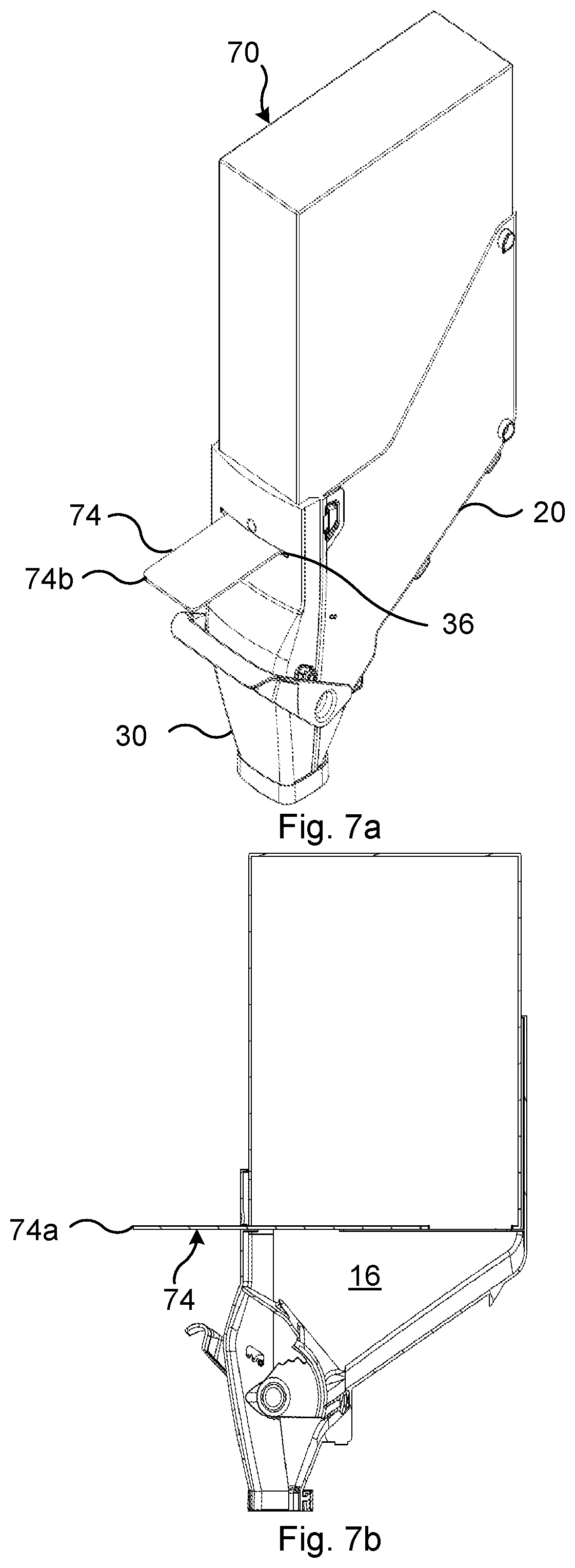
FIELD OF THE INVENTION
[0002] The invention relates to a gravity feed dispenser for bulk material products. Within the food retail industry, such dispensers are often referred to as gravity bins. The invention also relates to a stationary holder forming part of the gravity feed dispenser.
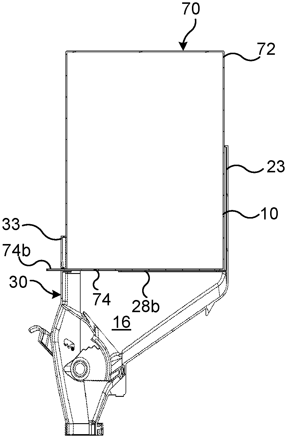
BACKGROUND
[0003] Bulk material goods or products (hereinafter bulk products), such as grain, coffee, tea, nuts, spices, candy etc. are often sold by the weight in supermarkets and commodity stores. By this means, the customers are allowed to freely choose the desired quantity to purchase. There exist several different types of containers for storing, displaying and providing such bulk products to the customers in the stores.
[0004] One type is the so called scoop bins, at which the customers gain access to the bulk product via an openable lid and use a scoop to manually shovel goods from the container to a pouch, a bag, a jar or the like, which is brought to the check-out counter for weighing and paying. However, scoop bins entail certain disadvantages and problems. Since the outlet lid is openable, the bulk product stored in the container is exposed to contaminations from the surrounding atmosphere and from the customers. Additionally, the use of a scoop for manually transferring the goods from the scoop bin to customer's receptacle may cause considerable spillage, waste and littering in the store.
[0005] Another type of container for storing, displaying and providing bulk products is the so called gravity feed dispensers. These devices normally comprise a vertically oriented container having an upper closable inlet for filling and refilling and a lower outlet provided with a manually operable valve. The container is thus filled and refilled by store personnel having access to the upper inlet opening. Gravity acts on the bulk product stored in the container and urges it toward the lower outlet opening. The customer holds a bag, a pouch or other receptacle under the outlet and manually opens the valve, whereby the desired amount of the bulk product is poured by gravity into the customer's receptacle. At this type, the risk of contamination is greatly reduced since the bulk product stored in the container is not exposed to the surrounding atmosphere and since the outlet valve prevents the customers from getting access to the interior of the container. Additionally, pouring of the bulk product into a receptacle held beneath the outlet reduces the risk of spillage and the problems related thereto.
[0006] Gravity feed dispensers for storing, displaying and providing bulk products should preferably exhibit some important qualities. Especially when they are used for storing foodstuff, the hygienic aspect is important. Therefore it is desirable to minimize the exposure of the product to the surrounding atmosphere. It is also important that refilling of the dispenser can be carried out quickly and easily. A further important aspect is that it is easy to wash and keep the interior of the dispenser and other parts making contact with the bulk product clean. It should thus preferably be easy for maintenance personnel to disassemble and get access to the interior of the dispenser. For the same reason it is important that the container exhibits a minimum of cavities, recesses or slits in which the bulk product or dust thereof may be caught. For economical reasons it is beneficial if the dispenser comprise a low number of constituent components and is easy to disassemble and reassemble. Also from a manufacturing point of view and for ascertain reliability and long service life, it is advantageous when the container comprises only a few constituent parts.
PRIOR ART
[0007] U.S. Pat. No. 5,375,744 discloses a device for measuring and dispensing granular material, which device comprises a body member which defines a hopper with a discharge opening and a discharge port disposed below the discharge opening. A dispensing cylinder is rotably mounted in the body, between the discharge opening and port. The body also includes a removable top cover and a removable front cover.
[0008] U.S. Pat. No. 6,241,123 B1 discloses a bulk food dispensing apparatus comprising a bin exhibiting an upper opening for loading a bulk product and a lower opening. A rotating door which is operable by a handle is arranged at the lower opening for allowing the bulk product stored in the bin to flow under the force of gravity out through the lower opening. According to this document, the bin comprises a left side piece and a right side piece which are interconnected along a rear side and thereby form a first cavity. A front piece is connected to the left and right side pieces for securing these together and for defining a second cavity in front of the first cavity.
[0009] U.S. Pat. No. 6,182,864 B1 discloses a similar apparatus wherein the left and right side pieces are hingedly connected and secured by a front piece.
[0010] U.S. Pat. No. 8,870,024 B2 and U.S. Pat. No. 6,702,157 B2 disclose further examples of gravity feed dispensers comprising a container formed of two interconnected side pieces and a manually rotable gate or door for selectively blocking and allowing flow of a bulk product stored in the container through an discharge opening.
[0011] SE532075C2 discloses a method of hygienic handling of bulk products at which the bulk product is filled into a distribution bag which thereafter is laced-up by means of a string. The bag is transported from the factory to the end customer. After transportation, the bag is placed in a hopper of a dispensing unit, with the laced-up end down and the bag is opened by pulling the string. This document also discloses a device for such handling which device comprises a dispensing unit and a distribution bag.
[0012] GB2049625A discloses an apparatus for storing and apportioning powdered or granular material. The apparatus comprises a holder for a package and an apportioning device. The package comprises a strip-like sealing closure with a strip flap for opening the package when placed in the holder.
SUMMARY
[0013] An object of the invention is to provide an enhanced gravity feed dispenser for bulk products.
[0014] Another object is to provide such a dispenser which, in use, minimizes the exposure of the bulk product to the surroundings atmosphere.
[0015] A further object is to provide such a dispenser which facilitates transportation of the bulk product and refilling of the dispenser.
[0016] Yet another object is to provide such a dispenser which reduces the risk of spillage at refilling the dispenser.
[0017] Still another object is to provide such a dispenser which is easy to wash and clean.
[0018] A further object is to provide such a dispenser which comprises only a low number of constituent parts.
[0019] Yet another object is to provide such a dispenser which may easily be disassembled and reassembled by maintenance personnel.
[0020] A still further object is to provide such a dispenser which is reliable in use and has a long service life.
[0021] A further object is to provide such a dispenser which alleviates the need to dismount and remove the dispenser from its normal operating position in a rack or the like, for allowing cleaning of the interior.
[0022] According to a first aspect, these and other objects are achieved by a gravity feed dispenser according to claim 1. The gravity feed dispenser is intended for use with an exchangeable container with a tearable bottom portion which container holds a bulk product. The gravity feed dispenser comprises a stationary holder comprising a seat portion arranged to receive at least a lower portion of the exchangeable container, an outlet opening for dispensing the bulk product and a valve arrangement which is arranged operatively between the seat portion and the outlet opening, for selectively allowing and preventing outward flow of the bulk product from the exchangeable container through the outlet opening. The seat portion comprises essentially vertically arranged opposed side wall portions, a rear wall portion and a front wall portion arranged to receive at least a lower portion of the exchangeable container when inserted from above. The front wall portion of the seat portion exhibits a slit configured to allow removal of said tearable bottom portion of the exchangeable container through the slit.
[0023] By providing the gravity feed dispenser with a stationary holder for such an exchangeable container containing the bulk product, a number of advantages are achieved. The bulk product contained in the exchangeable container may efficiently be transported from the supplier to the shop or other location where the bulk product is to be dispensed. Transport and handling of the product may also be carried out without the risk of contaminating the product. Additionally, at refilling of the gravity feed dispenser, the entire exchangeable container may readily be mounted to the holder and kept there until the entire content has been dispensed. This greatly facilitates handling of the product since it alleviates the need of scoping, pouring and other means of transferring the product from a separate transport container to a hopper or the like of the gravity feed dispenser. By this means, spillage and contamination of the bulk product during refilling is also eliminated. The use of an exchangeable container with a gravity feed dispenser thus enhances the efficiency and the hygienic aspects of all handling of the bulk product from the manufacturer of the product to the end customer.
[0024] The seat portion arranged at the upper part of the stationary holder allows for very easy mounting and removal of the exchangeable container. The side, rear and front wall portions forming part of the seat portion further enhances reliable fixation of the exchangeable container when mounted to the stationary holder. To this end, the distances between the wall portions of the seat portion may be chosen such that the exchangeable container is received in the seat portion with a tight fit. The slit arranged in the front wall portion of the seat portion allows for that the tearable bottom portion may readily be removed from the exchangeable container for opening of the container, after full mounting the container to the holder. By this means exposure of the bulk product to the surrounding atmosphere is prevented or at least minimized.
[0025] The stationary holder may comprise a removable lid which, when mounted to the holder, closes the slit. By this means dust and other contaminations is prevented from coming into contact with the bulk material in the dispenser also when the container has been opened and the bottom portion removed.
[0026] The lid may be formed as a label holder. By this means information about the bulk product such as content and price may readily be displayed to the customers.
[0027] The lid and/or the stationary holder may be provided with sealing means. By this means ingression of foreign matter into the bulk product is further reduced.
[0028] The lid and the stationary holder may be provided with cooperating snap-fit means for snap-fit mounting of the lid to the stationary holder. Hereby mounting and dismounting the lid is facilitated.
[0029] The stationary holder may comprise a lower chute portion for conducting the outflow of the bulk product.
[0030] The holder may comprise a body member and a front piece, which body member is formed in one single piece and comprises two opposing side walls, a rear wall and a forwardly sloping bottom wall and which front piece is removably attached to the body member and comprises a front wall. By this means the holder may easily be opened for allowing washing and cleaning by simply removing a single component.
[0031] The valve arrangement may comprise a pivotal valve member and a maneuvering handle. This allows for easy and reliable operation of the valve for dispensing the bulk product.
[0032] The handle may be connected to the valve member by two axles which are pivotally received in semi circular openings formed in the body member and the front piece. This facilitates disassembling and reassembling of the holder, e.g. at washing, cleaning and other maintenance operations.
[0033] The gravity feed dispenser may further comprise an exchangeable container with a tearable bottom portion for storing a bulk product.
[0034] The dimensions of a horizontal cross section of the exchangeable container and the corresponding distances between the wall portions of the stationary holder may be chosen such that the container is received with a tight fit in the seat portion. Hereby the container is securely fixed to the stationary holder when mounted.
[0035] The tearable portion may be arranged at a bottom wall of the container when the container is held by the stationary holder. By this means the bulk product will automatically be fed by gravity to the valve of the dispenser.
[0036] The holder and the container may be arranged for allowing the tearable portion to be removed from the container when it is held by the holder. This efficiently eliminates the risk of spillage of the bulk product during refilling.
[0037] The tearable portion may extend onto a front wall of the container. By this means access to the tearable portion is enhanced and opening of the container is facilitated.
[0038] The tearable portion may be delimited by a first tear line in the container. This facilitates tearing of the tearable portion. The tear line may be constituted by or comprise a perforation line or any other kind of line of weakness.
[0039] The exchangeable container may comprise a cardboard box. Such boxes are comparatively affordable and also advantageous from an environmental point of view. In addition they are comparatively light in weight and easy to handle also since they may be made stackable.
[0040] Further objects and advantages of the invention will be apparent from the following description of embodiments and from the appended claims.
[0041] Generally, all terms used in the claims are to be interpreted according to their ordinary meaning in the technical field, unless explicitly defined otherwise herein. All references to "a/an/the element, apparatus, component, means, step, etc." are to be interpreted openly as referring to at least one instance of the element, apparatus, component, means, step, etc., unless explicitly stated otherwise. The steps of any method disclosed herein do not have to be performed in the exact order disclosed, unless explicitly stated.
BRIEF DESCRIPTION OF THE DRAWINGS
[0042] The invention is now described, by way of example, with reference to the accompanying drawings, in which:
[0043] FIG. 1 is a perspective view of a gravity feed dispenser according to an exemplifying embodiment of the invention.
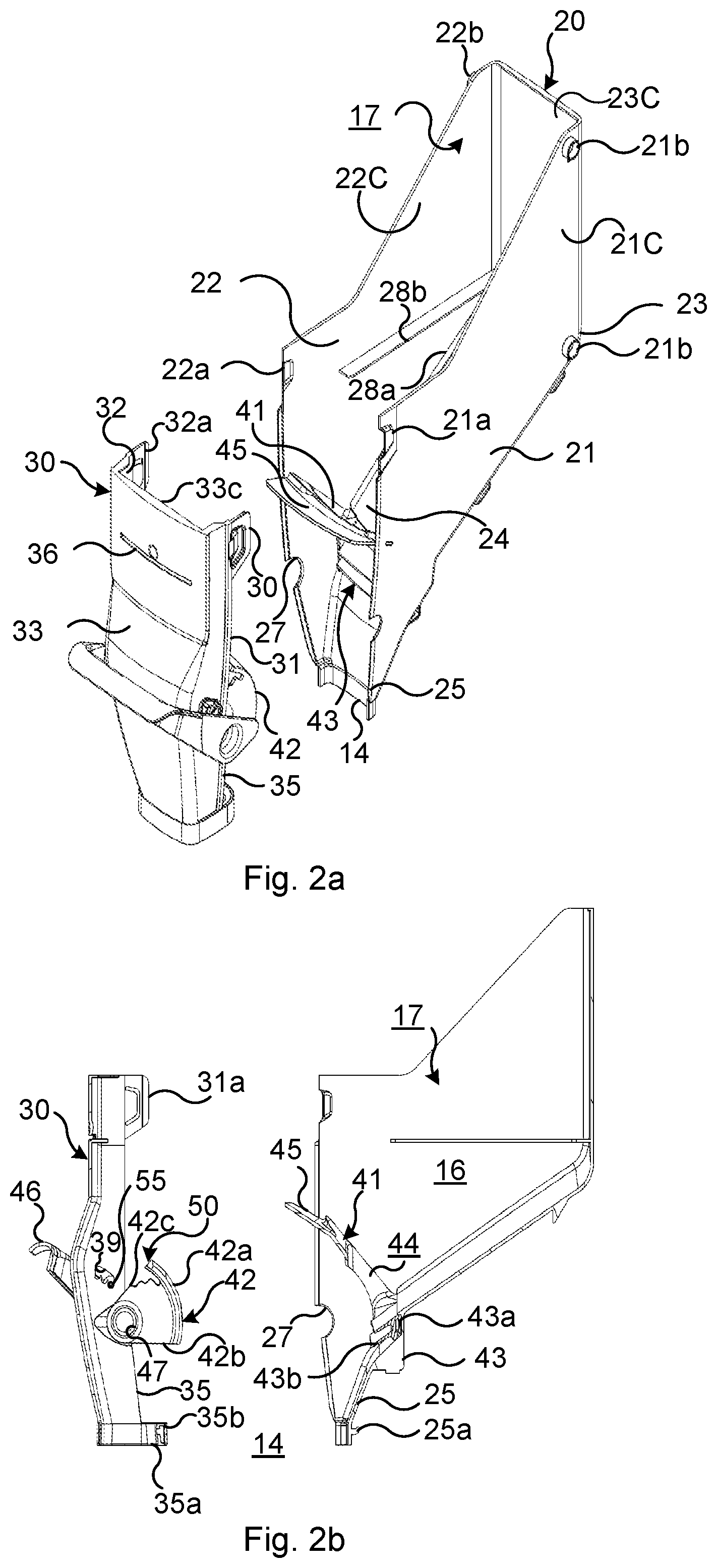
[0044] FIG. 2a is an exploded perspective view of a stationary holder comprised in the gravity feeder shown in FIG. 1 and FIG. 2b is a section through the holder shown in FIG. 2a.
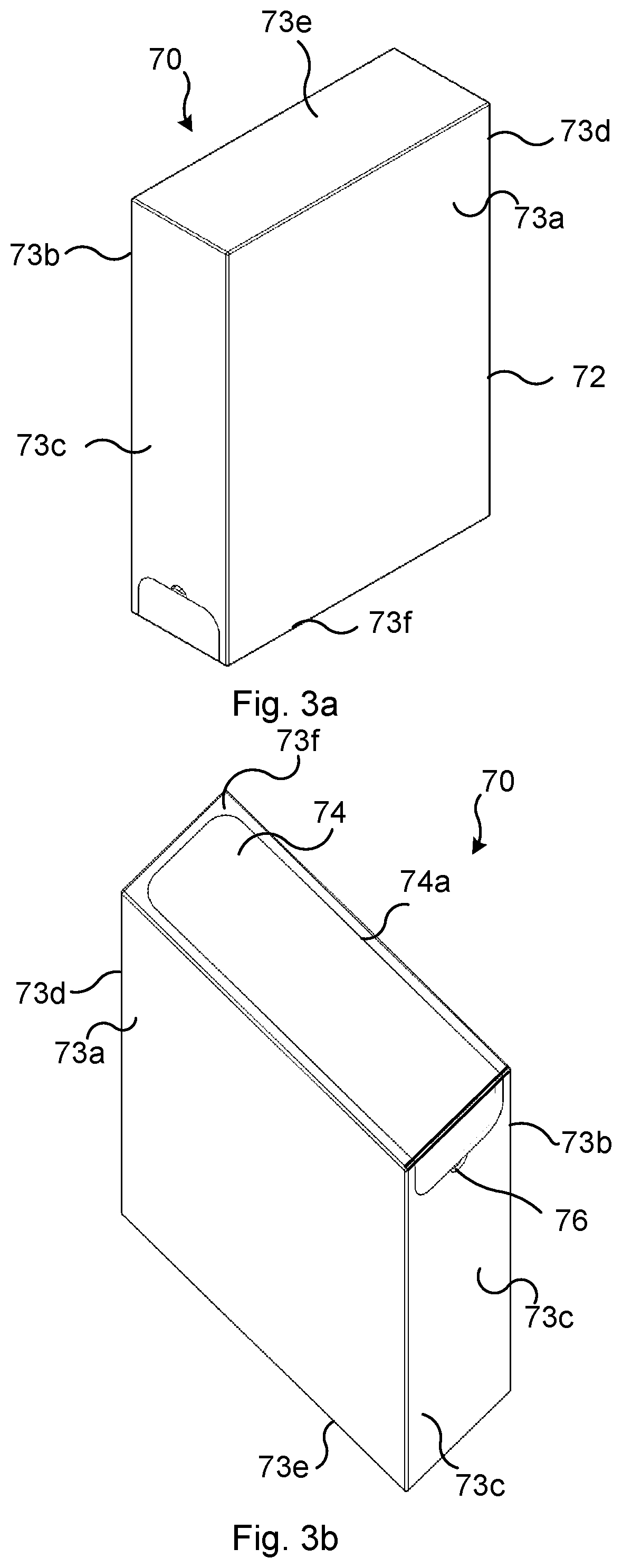
[0045] FIG. 3a is a perspective view obliquely from above of an exchangeable container comprised in the gravity feed dispenser shown in FIGS. 1 and 3b is a perspective view obliquely from below of the container shown in FIG. 3a.
[0046] FIG. 4 is perspective view obliquely from below of the container shown in FIGS. 3a-b illustrating a step in preparing it for final opening.
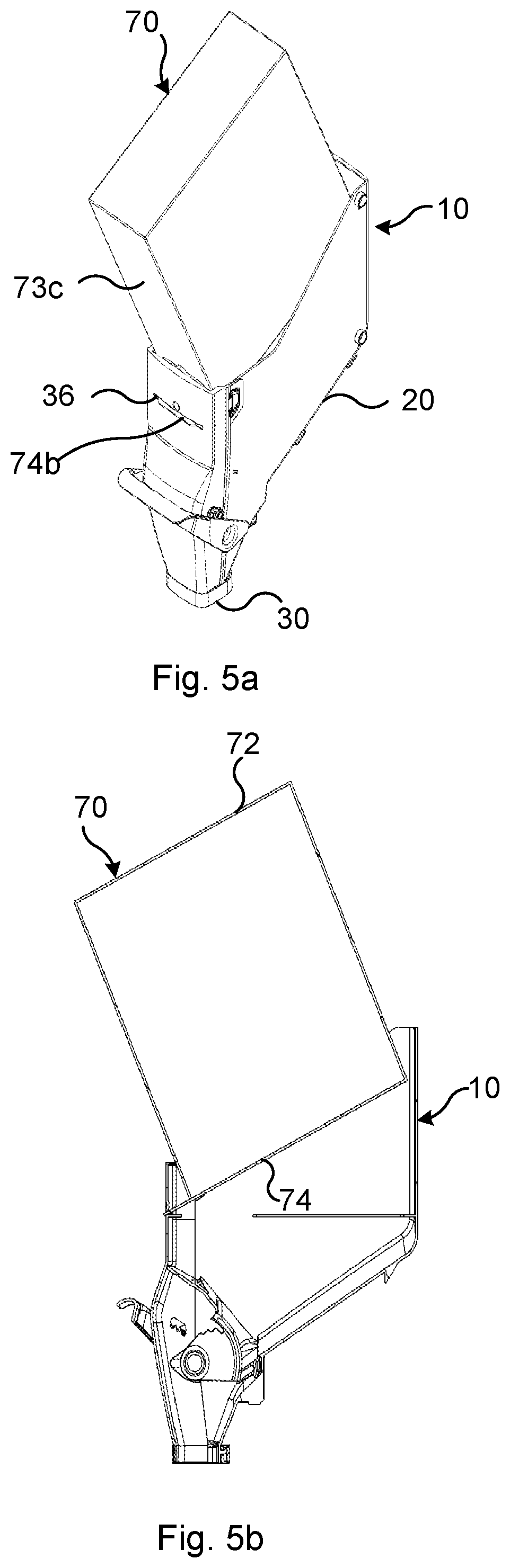
[0047] FIG. 5a is a perspective view of the gravity feed dispenser shown in FIG. 1 illustrating a step of introduction of the container into the holder and FIG. 5b is a section illustrating the same step of introduction.
[0048] FIG. 6a is a perspective view of the gravity feed dispenser shown in FIG. 1 and illustrating the container fully inserted into the holder. FIG. 6b is a section of FIG. 6a.
[0049] FIG. 7a is a perspective view of the gravity feed dispenser shown in FIG. 1 illustrating a final stage of opening the container and FIG. 7b is a section illustrating the same step of opening.
DETAILED DESCRIPTION
[0050] The invention will now be described more fully hereinafter with reference to the accompanying drawings, in which certain embodiments of the invention are shown. This invention may, however, be embodied in many different forms and should not be construed as limited to the embodiments set forth herein; rather, these embodiments are provided by way of example so that this disclosure will be thorough and complete, and will fully convey the scope of the invention to those skilled in the art. Like numbers refer to like elements throughout the description.
[0051] At the embodiment of the gravity feed dispenser shown in FIG. 1 it comprises a stationary holder 10 and an exchangeable container 70 for storing a bulk product, which container is constituted by a carton box. The holder 10 comprises a lower outlet opening 14 for dispensing a selectable amount of the bulk product into a bag or other receptacle (not shown) positioned under the outlet opening.
[0052] As best seen in FIGS. 2a and 2b, the holder 10 further comprises two major components 20, 30 which, when assembled, define an interior space 16 for receiving a lower portion of the container 70 and bulk material (not shown) delivered from the container. One of these major components is constituted by a body member 20, preferably formed as an integral single piece of material. In the shown example, the body member 20 has been formed by injection moulding of a durable transparent plastic material. However, other methods and materials for forming the one piece body member may also be used. The other major component is constituted by a front piece 30 which is releasably mounted to the front portion of the body member 20. In the shown embodiment also the front piece 30 is formed by injection moulding of a durable transparent plastic material but other methods and materials may be used.
[0053] At a not shown alternative embodiment, the body member may comprise two or more separate pieces which are attached together when assembling the holder. It may for example comprise two mirror symmetrical half pieces which are mutually snap-fitted or interconnected by other means for forming the body member.
[0054] The body member 20 comprises two first vertical sidewalls 21, 22 which are arranged mutually in parallel. A second vertical sidewall 23 forms a rear wall and extends between upper rear edge portions of the first sidewalls. A bottom wall 24 extends between the lower edge of the rear wall 23 and the lower edges of the two first sidewalls 21, 22. The bottom wall 24 slopes downwards in the forward direction from the rear wall 23 such that the bulk product received in the holder 10 is urged by gravity toward the lower front portion of the holder, where the outlet opening 14 is arranged. At the front lower portion of the body member 20, respective portions of the first sidewalls 21, 22 and the bottom wall 24 are arranged to form a downwardly directed first chute portion 25 having a generally U-shaped cross section. By this means the body member 20 exhibits a completely open front 26 which extends over the entire height of the body member 20. A number of mounting protrusions 21b, 22b are arranged laterally protruding at the rear portion of each first side wall 21, 22. These protrusions are arranged for mounting the gravity feed dispenser to a rack or stand (not shown) in a manner which is known per se. Normally, the stand is arranged for receiving a plurality of gravity feed dispensers side by side in rows and columns. The body member 20 further comprises two support flanges 28a, 28b which extend horizontally along the interior side of the first side walls 21, 22. These support flanges 28a, 28b form part of a seat portion 17 arranged for supporting the container 70 when inserted in the holder 10. The front piece 30 comprises a front wall 33 which constitutes a third side wall of the holder 10 when the front piece has been mounted to the body member 20. A first side wall portion 31, 32 extends rearwardly from respective lateral edges of the front wall 33. The rear edges of the first side wall portions 31, 32 are essentially equally long, in the vertical direction, as the front edges of the first side walls 21, 22 and provided with rearwardly open grooves (not shown) which receives respective front edges of the first side walls 21, 23 for secure mounting of the front piece 30 to the body 20. At the lower portion of the front piece 30 the front wall 33 and the two first side wall portions 31, 32 form a downwardly directed second chute portion 35 having a generally U-shaped cross section which corresponds to the cross section of the first chute portion 25. When the front piece 30 is mounted to the body 20, the first 25 and second 35 chute portions together define a tubular chute which is arranged to guide and conduct the bulk product towards the outlet opening 12.
[0055] The front piece 30 further exhibits an opening in the form of a trough penetrating horizontal slit 36 which is arranged to facilitate opening of the container 70 by allowing a tear portion 74 of the container to be removed through the slit 36. This will be explained more in detail below. A lid 37 (see FIG. 1) may be snap-fitted onto the front wall 33 of the front piece 30. When mounted, the lid 37 closes the slit 36 and prevents foreign material from entering into the open space 16 of the holder 10. At some applications the lid 37 or the front piece 30 may be provided with sealing means further reducing the influence of the surrounding atmosphere to the bulk product contained in the gravity feed dispenser. In the shown example the lid 37 is formed and functions as a label holder for holding a label (not shown) with information about the bulk product.
[0056] The support flanges 28a, 28b and upper wall portions 21c, 22c, 23c, 33c arranged above the support flanges 28a, 28b of the respective walls 21, 22, 23, 33 form a seat portion 17 of the holder 10 for receiving and securely holding a lower portion of the container 70.
[0057] The gravity feed dispenser further comprises a valve arrangement 40 for selectively allowing and preventing flow of the bulk product from the interior space 16 through the outlet opening 14. The valve arrangement 40 comprises a valve seat member 41, a pivotal valve member 42 and a flexible sealing 43. The valve seat member 41 exhibits a valve opening 44 and a partition wall 45 which is arranged in the interior space 16 of the of the holder 10, such that the effective outflow area is reduced to the dimensions of the valve opening 44. The valve seat member 41 is attached to the body member 20 by snap-fit means (not shown) arranged at the first side walls 21, 22 and the lateral sides of the valve seat member 41.
[0058] In the shown example, the valve seat member 41 is formed by injection moulding a plastic material and the sealing 43 is formed by injection moulding of a resilient material, such as a rubber material. Other methods and materials may be used as long as the sealing is formed of flexible and resilient material which remains in sealing contact with the pivotal valve member 42 during its pivotal movement. The sealing 43 comprises a base (not denoted) exhibiting a fixation channel 43a and two sealing lips 43b which extend in parallel from the base at the side being opposite to the fixation channel 43a. The sealing 43 may be mounted to and dismounted from the valve seat member 41 when the valve seat member 41 is dismounted from the body 20. The sealing 43 is mounted to the valve seat body 41 by resilient formfitting of the fixation channel 43a around a valve seat bar (not shown) which delimits the valve opening 44. When the sealing 43 has been mounted to the valve seat member 41, these two components may be jointly snap-fit fixed to the body 20 by engaging the snap-fit means (not shown) of the valve seat body into corresponding snap-fit means (not shown) of the body 20.
[0059] The pivotal valve member 42 exhibits an arced valve wall 42a, with which the flexible sealing lips 43b makes sealing contact. A valve bracket 42b connects each lateral side of the valve wall 42a to a respective axle 47, which axles are axially aligned and define the pivotal axis for the pivotal valve member 42 and the valve wall 42a. The axles 47 are in turn fixed to an operating handle 46 by means of which the valve member 42 and the valve wall 42a may be manually pivoted about its pivotal axis.
[0060] When mounted to the holder 10, each shaft 47 is received in respective semi circular recesses 27 formed in the opposing and engaging edges of the first side walls 21, 22 and the first side wall portions 31, 32. By this means the valve member 42 and the handle 46 are together pivotally journaled to the holder when the front piece 30 is mounted to the body member 20. The valve member 42, the shafts 47 and the handle 46 together form a valve shutter 50 which may be mounted to and dismounted from the container 10 as a single component. In the preferred embodiment shown, the valve shutter 50 is formed as a single integral piece of material, e.g. by injection moulding of a plastic material. However, other methods and materials for forming the valve shutter 50 are also possible.
[0061] The sealing 43 comprises two sealing lips that resiliently follow the surface of the valve member 42 during its pivotal movement. By this means also fine particles, such as powder and dust are prevented from exiting the container when the valve member is in its closed position.
[0062] The valve arrangement 40 also comprises a biasing means (not shown) for urging the valve member 42 and the handle 46 to its closed position when no opening force is applied to the handle. These means comprises an elastic string arranged at each lateral side of the valve shutter 50.
[0063] The valve arrangement 40 further comprises means for adjusting its effective maximum opening area. These means comprises a rod 55 which extends laterally through the front piece 30. Each first side wall portion 31, 32 is provided with an elongate through opening 39 which exhibits a number of adjustment slots (not denoted) arranged one after the other along the longitudinal direction of the elongate through opening 39. The rod 55 may be inserted into the elongate through openings 39 and its end portions may be positioned into a desired pair of adjustments slots. The rod 55 may thereafter be fixed in the adjustment slots by fixing a securing sleeve (not shown) onto each end of the rod 55. The valve shutter 50 exhibits a number of adjustment notches 42c formed in an edge of the valve member's 42 brackets 42b, one after the other in the pivotal direction of the valve shutter 50. Depending on the adjustment position chosen for the rod 55 in the elongate through openings 39, only one notch 42c at each bracket 42b will make contact with the rod 60 when the valve shutter 50 is pivoted in its opening direction. This contact between a notch 42c and the rod 55 blocks the valve shutter from further pivoting in the opening direction and thereby defines the selected fully opening area of the valve opening 44. Such easily accomplished adjustment of the maximum valve opening area is very useful when the gravity feed dispenser is to be used for bulk products having different particle sizes and density, and where it is necessary to adjust the dispensing flow rate.
[0064] The front piece 30 is easily releasably fixed to the body 20 by snap-fitting. The body member 20 comprises a protruding hook 25a which extends rearwardly from a lower rear portion of the first chute portion 25. The front piece 30 comprises a corresponding hollow collar 35a which extends rearwardly from the lower edge of the second chute portion 35. A through opening 35b is provided at the rear side of the collar.
[0065] The body member 20 further comprises laterally protruding first snap-fit means comprising bulges 21a, 22a arranged at the upper front edges of side walls 21, 22. The front piece 30 comprises corresponding second snap-fit means 31a, 32a arranged at the upper rear edges of first side wall portions 31, 32. In the shown example these second snap fit means each comprise a tongue which is insertable inside a respective bulge 21a, 22a and a resilient hollow tab which is arranged to receive a respective bulge 21a, 22a by snap-fitting around the bulge.
[0066] The front piece 30, with the shutter valve 50 mounted (as described above) is very easily releasably fixed to the body 20. The upper end of front piece 30 is first tilted away from the body 20 and the lower end of the first chute portion 25 is introduced into the hollow collar 35a of the front piece 30. Thereafter or simultaneously, the hook 25a is inserted and engaged with the through opening 35b in the collar 35a. When so engaged the upper portion of the front piece 30 is pivotally tilted toward the body until the two tongues are inserted inside the bulges 21a, 22a and the hollow tabs snap around the periphery of the bulges 21a, 22a. By this means the front piece 30 is securely and releasably fixed to the body member 20 at the same time as the shutter valve 50, the valve seat member 41 and the seal 43 are locked in position. When the front piece 30 has been mounted to the body member 20 a friction sleeve (not shown) may be threaded onto hollow collar 35a. The friction sleeve may assist in holding the mouth of a pouch, a bag or the like when dispensing the bulk material from the gravity feed dispenser.
[0067] The holder 10 of the gravity feed dispenser may very easily be completely disassembled simply by releasing the hollow tabs from the bulges 21a, 22a, pivoting the upper portion of the front piece away from the body member 20 and thereafter releasing the hook 25a from the through hole 35. When the front piece 30 has been detached, the shutter valve 50 may be dismounted by first removing the elastic strings (not shown) and lifting out the shutter valve 50. Correspondingly the valve seat member 41 may easily be removed by disengaging snap means (not shown), pulling out the valve seat member 41 from the body 20 and thereafter removing the seal 43 from the valve seat member 41. If needed the rod 55 may be easily be removed by releasing one fixation sleeve (not shown) and withdrawing the rod 55 from the opposite end.
[0068] Thus, by only a very few and simple manual operations, holder 10 may be completely disassembled into its constituent parts whereby washing, flushing and other maintenance is greatly facilitated. Additionally, by simply removing the front piece 30 and the valve seat member 41 from the body member 20, the body becomes completely open in the forward and upward direction whereby all interior walls of the body member are easily accessible for washing and flushing. The low number of constituent part also allows for that the assembled gravity feed dispenser exhibits only a low number of component joints, thereby reducing the risk of fine particles and dust to be caught and collected in such joints.
[0069] The container 70 (best seen in FIGS. 3a-7b) comprises a rigid or semi-rigid box 72. Typically, the box 72 is formed of cardboard, plastic or other suitable material such that it, when filled with bulk products, is ridged enough to sustain stacking of several bag-in-boxes one op top of the other. For environment protection purposes, recyclable cardboard or other paper pulp based materials are preferred for forming the box.
[0070] As shown in FIGS. 3a-b the box 72 has a generally cuboid shape. It comprises two side walls 73a, 73b, a front wall 73c, a rear wall 73d, a top wall 73e and a bottom wall 73f.
[0071] As best seen in FIG. 3b, the bottom wall 73f exhibits a tearable portion 74 which is delimited by a first tear line 74a. The tearable portion 74 extends over almost the entire bottom wall area. The tear line 74a may be formed of perforated lines arranged in the box. Alternatively, the tear line 74a may be formed of other lines of weakness, such as lines of reduced material thickness or the like.
[0072] In the shown example, the tear portion 74 extend over the lower front edge of the outer box 70, a short distance into the front wall 73c. A release opening 76 is formed in the front wall 73c, adjacent to the tear portion 74.
[0073] Use of the inventive gravity feed dispenser will now be explained with reference to FIGS. 3a-7b.
[0074] When refilling the gravity feed dispenser, the previously used and emptied container is removed from the stationary holder 10. A new container 70, filled with a bulk product is first prepared for opening by inserting a finger into the release opening 76 and tearing loose a front portion of the tear portion 74 as shown in FIG. 4a. Thereby, a front portion of the tearable portion 74 which extends over the front wall 73c, may be folded out to form a grip tab 74b as shown in FIG. 4c. By this means the container 70 has been prepared for final opening after mounting to the holder 10 of the gravity feed dispenser. The front wall 73c of the container 70 may comprise two layers of wall material and the tearable portion 74 and tear line 74a extending onto the front wall 73 may the extend only through the outer layer. By this means, no through penetrating opening in the front is formed when the when the grip tab 74b has been released from the front wall 73c.
[0075] As shown in FIG. 5a-b, the container 70 is thereafter inserted into the holder 10 by inserting a lower portion of the box 72 between the upper wall portions 21c, 22c, 23c, 33c of the holder 10. Simultaneously the previously released grip tab 74b is inserted through the slit 36 of the front piece 30. Thereafter and as shown in FIGS. 6a-b the bag-in-box 70 is fully inserted into the holder 10, such that the bottom wall 73f is supported by the horizontal flanges 28a, 28b and the side walls 73a, 73b, the front wall 73c and the rear wall 73d of the outer box 72 are supported by the upper wall portions 21c, 22c, 23c, 33c of the holder 10.
[0076] When the container 70 has been prepared for opening and mounted to the holder 10 as described above it may be opened to allow an initial portion of the bulk product to be poured into the interior space 16 of the holder 10. This is accomplished simply by grabbing the grip tab 74b now extending through the slit 36 of the front piece and thereafter pulling the grip tap 74b. Since the grip tab 74b forms part of the first tearable portion 74 of the box, pulling the grip tab 74b will tear loose the entire tearable portion 74 from the box 72, thereby completely opening the container and allowing the bulk product to be poured by gravity into the interior space 16 of the holder 10.
[0077] When the tearable portion 74 has been removed through the slit 36, the slit 36 may be closed by attaching the lid 37 or by other closing means for preventing foreign particles or contamination to enter the interior space 16. If needed the slit or the closing means may be provided with additional sealing means (not shown) for sealing the interior space 16 from the surrounding atmosphere.
[0078] The invention has mainly been described above with reference to a few embodiments. However, as is readily appreciated by a person skilled in the art, other embodiments than the ones disclosed above are equally possible within the scope of the invention, as defined by the appended patent claims.
* * * * *
D00000
D00001
D00002
D00003
D00004
D00005
D00006
D00007
XML
uspto.report is an independent third-party trademark research tool that is not affiliated, endorsed, or sponsored by the United States Patent and Trademark Office (USPTO) or any other governmental organization. The information provided by uspto.report is based on publicly available data at the time of writing and is intended for informational purposes only.
While we strive to provide accurate and up-to-date information, we do not guarantee the accuracy, completeness, reliability, or suitability of the information displayed on this site. The use of this site is at your own risk. Any reliance you place on such information is therefore strictly at your own risk.
All official trademark data, including owner information, should be verified by visiting the official USPTO website at www.uspto.gov. This site is not intended to replace professional legal advice and should not be used as a substitute for consulting with a legal professional who is knowledgeable about trademark law.