Carrier For Containers
Smalley; Brian
U.S. patent application number 16/426063 was filed with the patent office on 2020-06-18 for carrier for containers. The applicant listed for this patent is Graphic Packaging International, LLC. Invention is credited to Brian Smalley.
| Application Number | 20200189817 16/426063 |
| Document ID | / |
| Family ID | 66912630 |
| Filed Date | 2020-06-18 |


View All Diagrams
| United States Patent Application | 20200189817 |
| Kind Code | A1 |
| Smalley; Brian | June 18, 2020 |
Carrier For Containers
Abstract
A package carrier for holding at least two container packages includes a handle and a plurality of panels including a top panel and at least one attachment panel. The top panel is for attachment to a top of the at least two container packages such that the at least two container packages are joined to the package carrier at the top panel.
| Inventors: | Smalley; Brian; (Bristol, GB) | ||||||||||
| Applicant: |
|
||||||||||
|---|---|---|---|---|---|---|---|---|---|---|---|
| Family ID: | 66912630 | ||||||||||
| Appl. No.: | 16/426063 | ||||||||||
| Filed: | May 30, 2019 |
Related U.S. Patent Documents
| Application Number | Filing Date | Patent Number | ||
|---|---|---|---|---|
| 62779689 | Dec 14, 2018 | |||
| 62783752 | Dec 21, 2018 | |||
| 62796830 | Jan 25, 2019 | |||
| 62797585 | Jan 28, 2019 | |||
| 62810015 | Feb 25, 2019 | |||
| 62814412 | Mar 6, 2019 | |||
| 62817120 | Mar 12, 2019 | |||
| 62841449 | May 1, 2019 | |||
| Current U.S. Class: | 1/1 |
| Current CPC Class: | B65D 71/44 20130101; B65D 2571/0032 20130101; B65D 2571/00493 20130101; B65D 2571/0045 20130101; B65D 2571/00141 20130101; B65D 71/406 20130101; B65D 71/38 20130101 |
| International Class: | B65D 71/40 20060101 B65D071/40; B65D 71/38 20060101 B65D071/38 |
Claims
1. A package carrier for holding at least two container packages, the package carrier comprising: a plurality of panels comprising a top panel and at least one attachment panel; and a handle, the top panel is for attachment to a top of the at least two container packages such that the at least two container packages are joined to the package carrier at the top panel.
2. The package carrier of claim 1, wherein each container package comprises a top panel, at least one side panel, and a plurality of container retention features supporting a respective container of a plurality of containers, and wherein the at least one attachment panel is for attachment to at least one container of the respective plurality of containers.
3. The package carrier of claim 2, wherein the at least one attachment panel is a front attachment panel and the plurality of panels further comprises a back attachment panel.
4. The package carrier of claim 2, wherein the handle comprises a front handle panel foldably connected to a back handle panel, the front attachment panel is foldably connected to the front handle panel, the back handle panel is foldably connected to the top panel, and the back attachment panel is foldably connected to the top panel.
5. The package carrier of claim 4, wherein at least one handle reinforcement panel is foldably connected to at least one of the front handle panel and the back handle panel.
6. The package carrier of claim 1, wherein the handle is foldably connected to the top panel and is reconfigurable between a first configuration, in which the handle is folded downwardly relative to the top panel, and a second configuration, in which the handle is folded upwardly relative to the top panel.
7. The package carrier of claim 6, wherein the handle comprises a front handle panel foldably connected to a back handle panel, and an exterior surface of the back handle panel faces away from the front attachment panel when the handle is in the first configuration.
8. The package carrier of claim 1, wherein the package carrier comprises at least one removable tear strip defined by at least one longitudinal tear line.
9. The package carrier of claim 8, wherein the at least one removable tear strip is a longitudinal tear strip that extends from a portion of the top panel to a free edge of the at least one attachment panel.
10. The package carrier of claim 9, wherein the package carrier further comprises a lateral removable tear strip defined by at least one lateral tear line extending between opposite free edges of the top panel.
11. The package carrier of claim 10, wherein the at least one longitudinal tear line intersects the at least one lateral tear line such that the longitudinal tear strip intersects the lateral tear strip.
12. The package carrier of claim 10, wherein the at least two container packages comprises a first container package and a second container package, and the longitudinal tear strip and the lateral tear strip are for being removed from the top panel such that a first portion of the top panel is for being attached to the first container package to form a first package carrier section and a second portion of the top panel is for being attached to the second container package to form a second package carrier section that is separate from the first package carrier section.
13. A blank for forming a package carrier for holding at least two container packages, the blank comprising: a plurality of panels comprising a top panel, at least one handle panel, and at least one attachment panel, the top panel is for attachment to a top of the at least two container packages when the package carrier is formed from the blank such that the at least two container packages are joined to the package carrier at the top panel.
14. The blank of claim 13, wherein each container package comprises a top panel, at least one side panel, and a plurality of container retention features supporting a respective container of a plurality of containers, and wherein the at least one attachment panel is for attachment to at least one container of the respective plurality of containers.
15. The blank of claim 14, wherein the at least one attachment panel is a front attachment panel and the plurality of panels further comprises a back attachment panel.
16. The blank of claim 14, wherein the handle comprises a front handle panel foldably connected to a back handle panel, the front attachment panel is foldably connected to the front handle panel, the back handle panel is foldably connected to the top panel, and the back attachment panel is foldably connected to the top panel.
17. The blank of claim 16, wherein at least one handle reinforcement panel is foldably connected to at least one of the front handle panel and the back handle panel.
18. The blank of claim 13, wherein the at least one handle panel is foldably connected to the top panel and is reconfigurable between a first configuration, in which the at least one handle panel is folded downwardly relative to the top panel, and a second configuration, in which the at least one handle panel is folded upwardly relative to the top panel.
19. The blank of claim 18, wherein the at least one handle panel is a front handle panel, and the at least one handle panel further comprises a back handle panel foldably connected to the front handle panel.
20. The blank of claim 13, wherein the blank comprises at least one removable tear strip defined by at least one longitudinal tear line.
21. The blank of claim 20, wherein the at least one removable tear strip is a longitudinal tear strip that extends from a portion of the top panel to a free edge of the at least one attachment panel.
22. The blank of claim 21, wherein the package carrier further comprises a lateral removable tear strip defined by at least one lateral tear line extending between opposite free edges of the top panel.
23. The blank of claim 22, wherein the at least one longitudinal tear line intersects the at least one lateral tear line such that the longitudinal tear strip intersects the lateral tear strip.
24. The blank of claim 22, wherein the longitudinal tear strip and the lateral tear strip are for being removed from the top panel to form a first portion of the top panel and a second portion of the top panel.
25. A method of forming a package carrier for holding at least two container packages, the method comprising: obtaining a blank comprising a plurality of panels that comprises a top panel, at least one handle panel, and at least one attachment panel; and attaching the top panel to a top of the at least two container packages such that the at least two container packages are joined to the package carrier at the top panel.
26. The method of claim 25, wherein each container package comprises a top panel, at least one side panel, and a plurality of container retention features supporting a respective container of a plurality of containers, and wherein the at least one attachment panel is for attachment to at least one container of the respective plurality of containers.
27. The method of claim 26, wherein the at least one attachment panel is a front attachment panel and the plurality of panels further comprises a back attachment panel.
28. The method of claim 26, wherein the handle comprises a front handle panel foldably connected to a back handle panel, the front attachment panel is foldably connected to the front handle panel, the back handle panel is foldably connected to the top panel, and the back attachment panel is foldably connected to the top panel.
29. The method of claim 28, wherein at least one handle reinforcement panel is foldably connected to at least one of the front handle panel and the back handle panel.
30. The method of claim 25, wherein the handle is foldably connected to the top panel and is reconfigurable between a first configuration, in which the handle is folded downwardly relative to the top panel, and a second configuration, in which the handle is folded upwardly relative to the top panel.
31. The method of claim 30, wherein the handle comprises a front handle panel foldably connected to a back handle panel, and an exterior surface of the back handle panel faces away from the front attachment panel when the handle is in the first configuration.
32. The method of claim 25, wherein the package carrier comprises at least one removable tear strip defined by at least one longitudinal tear line.
33. The method of claim 32, wherein the at least one removable tear strip is a longitudinal tear strip that extends from a portion of the top panel to a free edge of the at least one attachment panel.
34. The method of claim 33, wherein the package carrier further comprises a lateral removable tear strip defined by at least one lateral tear line extending between opposite free edges of the top panel.
35. The method of claim 34, wherein the at least one longitudinal tear line intersects the at least one lateral tear line such that the longitudinal tear strip intersects the lateral tear strip.
36. The method of claim 34, wherein the at least two container packages comprises a first container package and a second container package, and the longitudinal tear strip and the lateral tear strip are for being removed from the top panel such that a first portion of the top panel is for being attached to the first container package to form a first package carrier section and a second portion of the top panel is for being attached to the second container package to form a second package carrier section that is separate from the first package carrier section.
37. A package carrier in combination with at least two container packages, the combination comprising: the package carrier, the package carrier comprising a plurality of panels that comprises a top panel and at least one attachment panel, the package carrier further comprising a handle; and the at least two container packages, the top panel attached to a top of the at least two container packages such that the at least two container packages are joined to the package carrier at the top panel.
38. The combination of claim 37, wherein each container package comprises a top panel, at least one side panel, and a plurality of container retention features supporting a respective container of a plurality of containers, and wherein the at least one attachment panel is attached to at least one container of the respective plurality of containers.
39. The combination of claim 38, wherein the at least one attachment panel is a front attachment panel and the plurality of panels further comprises a back attachment panel.
40. The combination of claim 38, wherein the handle comprises a front handle panel foldably connected to a back handle panel, the front attachment panel is foldably connected to the front handle panel, the back handle panel is foldably connected to the top panel, and the back attachment panel is foldably connected to the top panel.
41. The combination of claim 40, wherein at least one handle reinforcement panel is foldably connected to at least one of the front handle panel and the back handle panel.
42. The combination of claim 37, wherein the handle is foldably connected to the top panel and is reconfigurable between a first configuration, in which the handle is folded downwardly relative to the top panel, and a second configuration, in which the handle is folded upwardly relative to the top panel.
43. The combination of claim 42, wherein the handle comprises a front handle panel foldably connected to a back handle panel, and an exterior surface of the back handle panel faces away from the front attachment panel when the handle is in the first configuration.
44. The combination of claim 37, wherein the package carrier comprises at least one removable tear strip defined by at least one longitudinal tear line.
45. The combination of claim 44, wherein the at least one removable tear strip is a longitudinal tear strip that extends from a portion of the top panel to a free edge of the at least one attachment panel.
46. The combination of claim 45, wherein the package carrier further comprises a lateral removable tear strip defined by at least one lateral tear line extending between opposite free edges of the top panel.
47. The combination of claim 46, wherein the at least one longitudinal tear line intersects the at least one lateral tear line such that the longitudinal tear strip intersects the lateral tear strip.
48. The combination of claim 46, wherein the at least two container packages comprises a first container package and a second container package, and the longitudinal tear strip and the lateral tear strip are for being removed from the top panel such that a first portion of the top panel is attached to the first container package to form a first package carrier section and a second portion of the top panel is attached to the second container package to form a second package carrier section that is separate from the first package carrier section.
Description
CROSS-REFERENCE TO RELATED APPLICATIONS
[0001] This application claims the benefit of each of U.S. Provisional Patent Application No. 62/779,689, filed on Dec. 14, 2018, U.S. Provisional Patent Application No. 62/783,752, filed on Dec. 21, 2018, U.S. Provisional Patent Application No. 62/796,830, filed on Jan. 25, 2019, U.S. Provisional Patent Application No. 62/797,585, filed on Jan. 28, 2019, U.S. Provisional Patent Application No. 62/810,015, filed on Feb. 25, 2019, U.S. Provisional Patent Application No. 62/814,412, filed on Mar. 6, 2019, U.S. Provisional Patent Application No. 62/817,120, filed on Mar. 12, 2019, and U.S. Provisional Patent Application No. 62/841,449, filed on May 1, 2019.
INCORPORATION BY REFERENCE
[0002] The disclosures of each of U.S. Provisional Patent Application No. 62/779,689, filed on Dec. 14, 2018, U.S. Provisional Patent Application No. 62/783,752, filed on Dec. 21, 2018, U.S. Provisional Patent Application No. 62/796,830, filed on Jan. 25, 2019, U.S. Provisional Patent Application No. 62/797,585, filed on Jan. 28, 2019, U.S. Provisional Patent Application No. 62/810,015, filed on Feb. 25, 2019, U.S. Provisional Patent Application No. 62/814,412, filed on Mar. 6, 2019, U.S. Provisional Patent Application No. 62/817,120, filed on Mar. 12, 2019, and U.S. Provisional Patent Application No. 62/841,449, filed on May 1, 2019, are hereby incorporated by reference for all purposes as if presented herein in their entirety.
BACKGROUND OF THE DISCLOSURE
[0003] The present disclosure generally relates to cartons or carriers for holding, displaying, and/or transporting containers.
SUMMARY OF THE DISCLOSURE
[0004] According to one aspect of the disclosure, a package carrier for holding at least two container packages comprises a plurality of panels comprising a top panel and at least one attachment panel. The package carrier further comprises a handle, and the top panel is for attachment to a top of the at least two container packages such that the at least two container packages are joined to the package carrier at the top panel.
[0005] According to another aspect of the disclosure, a blank for forming a package carrier for holding at least two container packages comprises a plurality of panels comprising a top panel, at least one handle panel, and at least one attachment panel. The top panel is for attachment to a top of the at least two container packages when the package carrier is formed from the blank such that the at least two container packages are joined to the package carrier at the top panel.
[0006] According to another aspect of the disclosure, a method of forming a package carrier for holding at least two container packages comprises obtaining a blank comprising a plurality of panels that comprises a top panel, at least one handle panel, and at least one attachment panel. The method further comprises attaching the top panel to a top of the at least two container packages such that the at least two container packages are joined to the package carrier at the top panel.
[0007] According to another aspect of the disclosure, a package carrier in combination with at least two container packages is provided. The package carrier comprises a plurality of panels that comprises a top panel and at least one attachment panel, and the package carrier further comprises a handle. The top panel is attached to a top of the at least two container packages such that the at least two container packages are joined to the package carrier at the top panel.
BRIEF DESCRIPTION OF THE DRAWINGS
[0008] Those skilled in the art will appreciate the above stated advantages and other advantages and benefits of various additional embodiments reading the following detailed description of the embodiments with reference to the below-listed drawing figures. It is within the scope of the present disclosure that the above-discussed aspects be provided both individually and in various combinations.
[0009] According to common practice, the various features of the drawings discussed below are not necessarily drawn to scale. Dimensions of various features and elements in the drawings may be expanded or reduced to more clearly illustrate the embodiments of the disclosure.
[0010] FIG. 1 is a plan view of an outer surface of a blank for forming a package carrier according to a first exemplary embodiment of the disclosure.
[0011] FIG. 2 is a perspective view of a pair of packages that can be supported by the package carrier of the first exemplary embodiment of the disclosure.
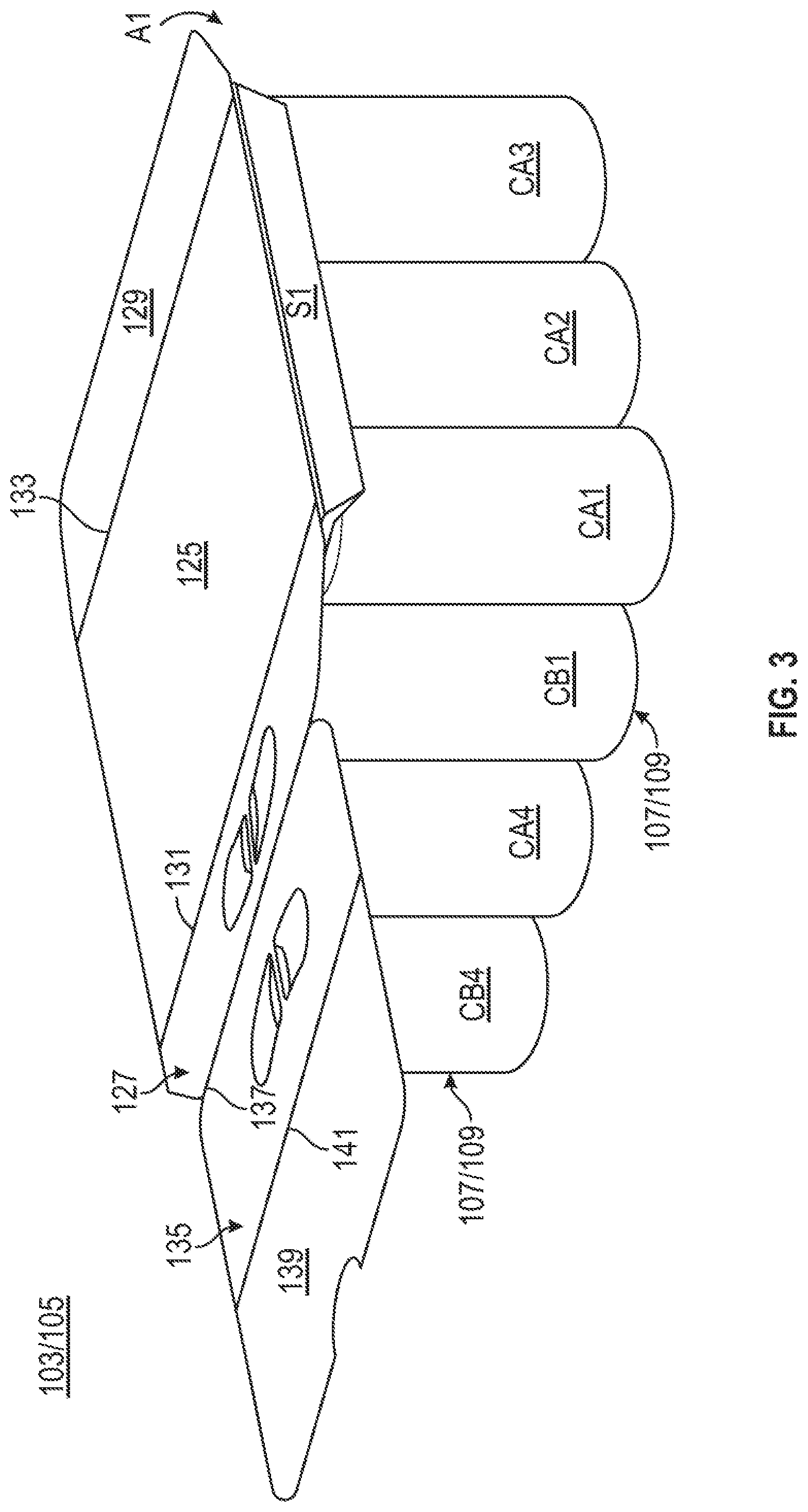
[0012] FIG. 3 is a perspective view of a partially folded configuration of a package carrier formed from the blank of FIG. 1 according to the first exemplary embodiment.
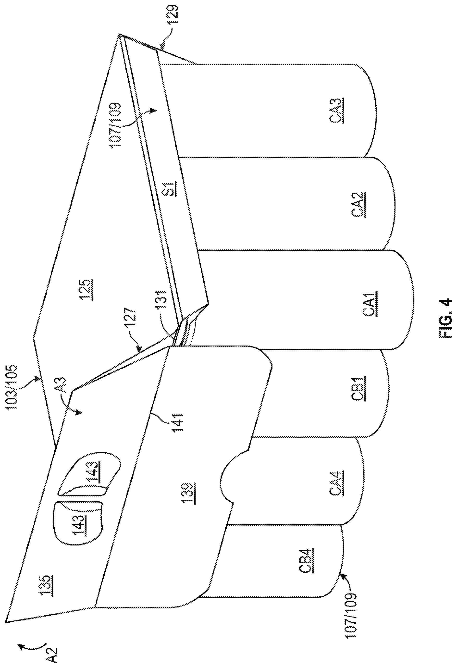
[0013] FIG. 4 is a perspective view of another partially folded configuration of a package carrier formed from the blank of FIG. 1 according to the first exemplary embodiment.
[0014] FIG. 5 is a perspective view of a package carrier formed from the blank of FIG. 1 and in a first configuration according to the first exemplary embodiment.
[0015] FIG. 6 is another perspective view of the package carrier of FIG. 5 in the first configuration.
[0016] FIG. 7 is a perspective view of the package carrier of FIG. 5 in a second configuration.
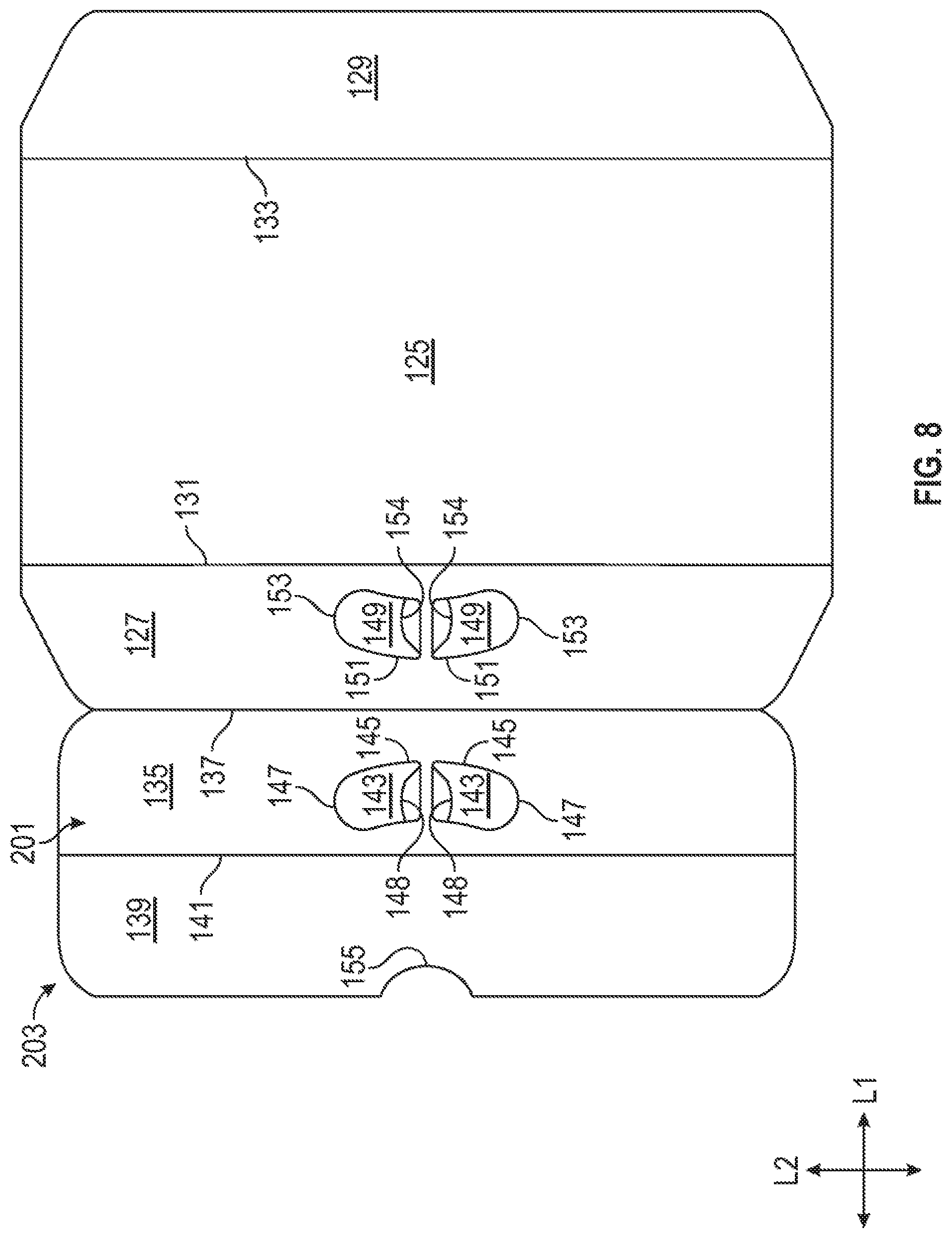
[0017] FIG. 8 is a plan view of an outer surface of a blank for forming a package carrier according to a second exemplary embodiment of the disclosure.
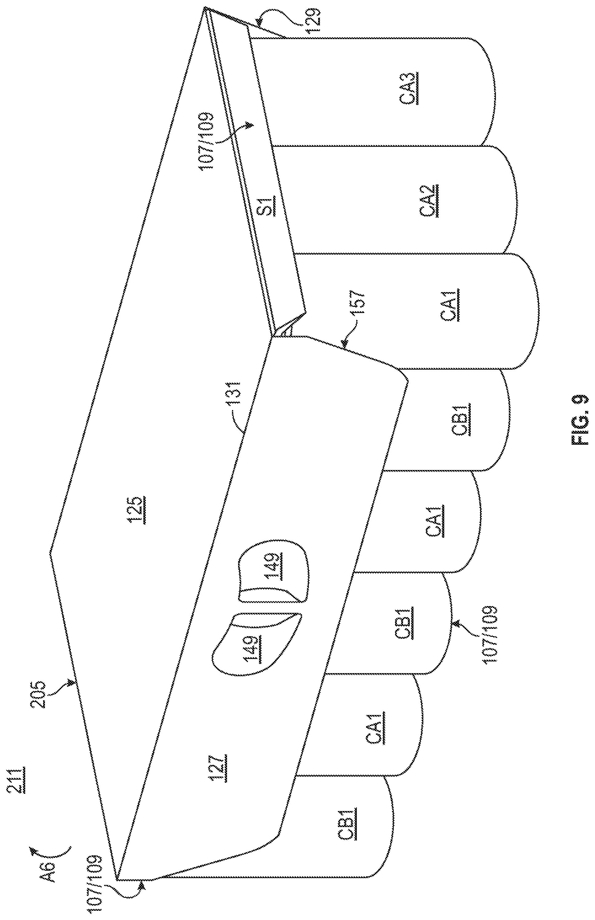
[0018] FIG. 9 is a perspective view of a package carrier formed from the blank of FIG. 8 according to the second exemplary embodiment.
[0019] FIG. 10 is a plan view of an outer surface of a blank for forming a package carrier according to a third exemplary embodiment of the disclosure.
[0020] FIG. 11 is a perspective view of a package carrier formed from the blank of FIG. 10 according to the third exemplary embodiment.
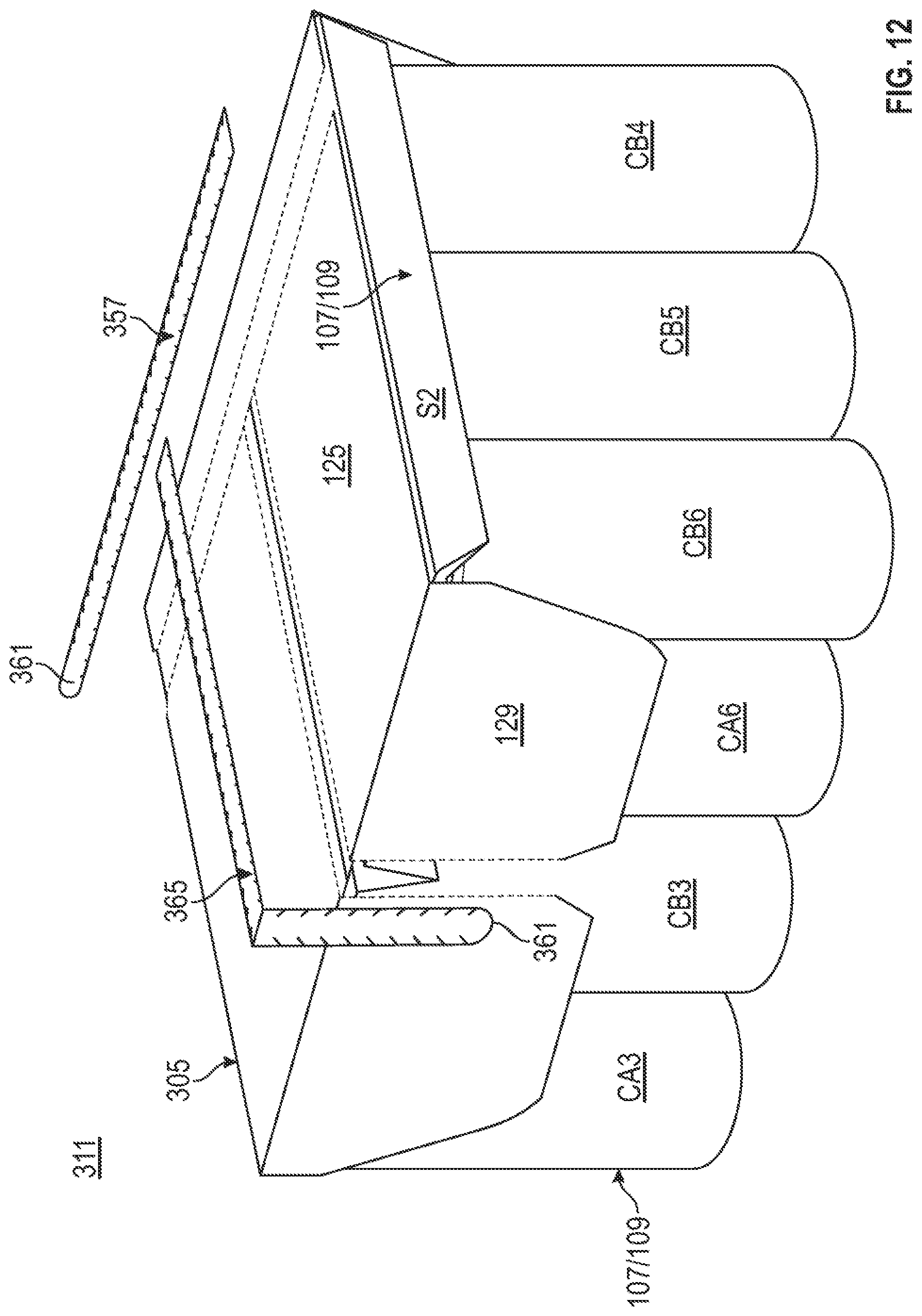
[0021] FIG. 12 is a perspective view of the package carrier of FIG. 11 with tear strips removed.
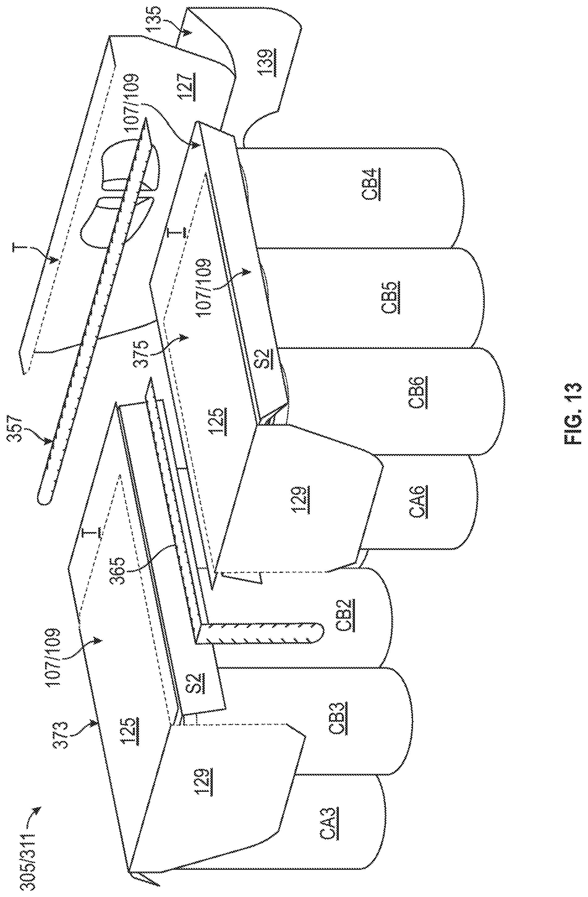
[0022] FIG. 13 is a perspective view of the package carrier of FIG. 12 having separated package carrier sections.
[0023] Corresponding parts are designated by corresponding reference numbers throughout the drawings.
DETAILED DESCRIPTION OF THE EXEMPLARY EMBODIMENTS
[0024] The present disclosure generally relates to carriers, packages, constructs, sleeves, cartons, or the like, for holding and displaying containers such as jars, bottles, cans, etc. The containers can be used for packaging food and beverage products, for example. The containers can be made from materials suitable in composition for packaging the particular food or beverage item, and the materials include, but are not limited to, glass; plastics such as PET, LDPE, LLDPE, HDPE, PP, PS, PVC, EVOH, and Nylon; and the like; aluminum and/or other metals; or any combination thereof
[0025] Carriers according to the present disclosure can accommodate containers of numerous different shapes. For the purpose of illustration and not for the purpose of limiting the scope of the disclosure, the following detailed description describes beverage containers (e.g., aluminum cans) at least partially disposed within the carrier embodiments. In this specification, the terms "lower," "bottom," "upper," "top," "front," and "back" indicate orientations determined in relation to fully erected carriers.
[0026] As described herein, carriers may be formed by multiple overlapping panels, end flaps, and/or other portions of blanks. Such panels, end flaps, and/or other portions of the blanks can be designated in relative terms to one another, e.g., "first", "second", "third", etc., in sequential or non-sequential reference, without departing from the disclosure.
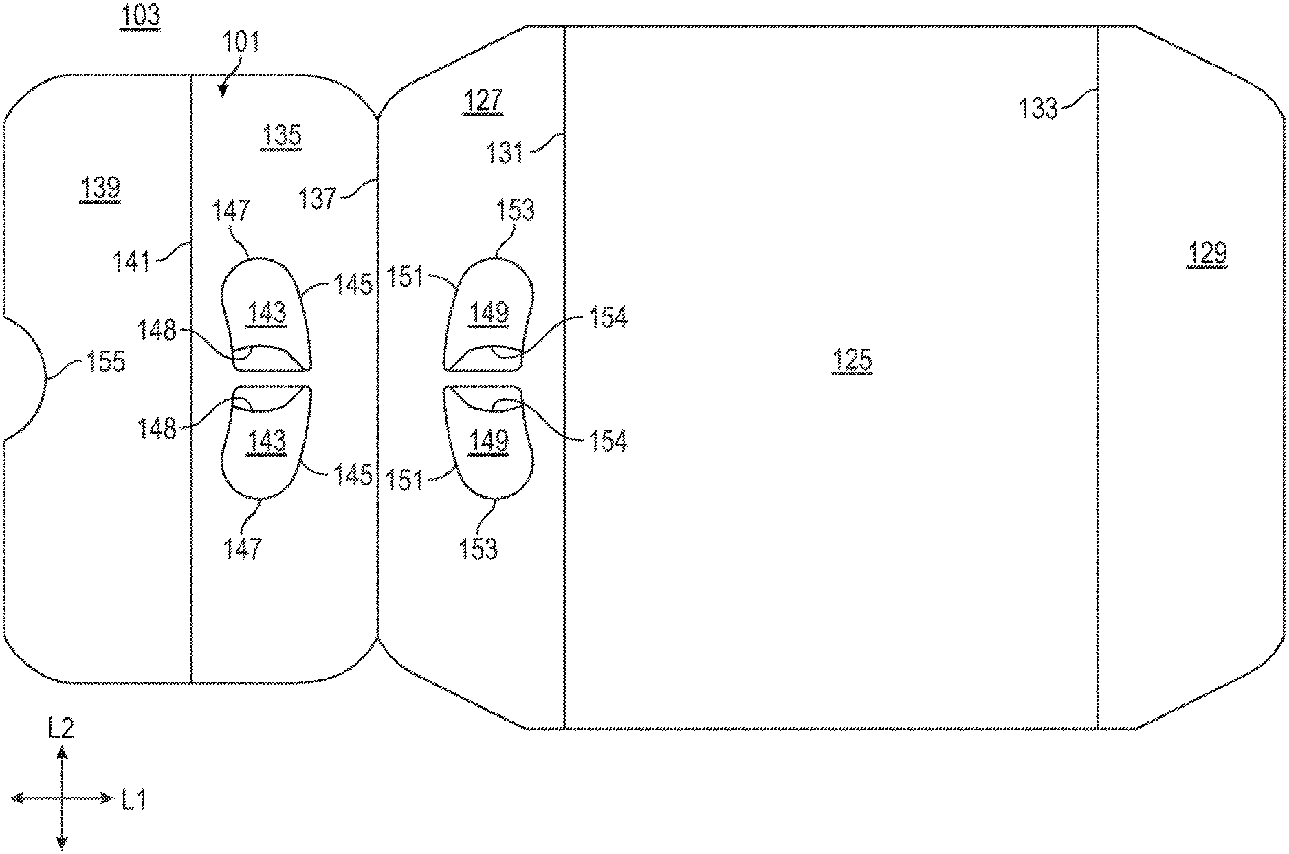
[0027] FIG. 1 shows a plan view of an exterior side 101 of a blank 103 used to form a handle construct or package carrier 105 (FIG. 3) in accordance with a first exemplary embodiment of the disclosure. As shown in FIG. 3, the package carrier 105 is sized and configured to extend at least partially around and support/hold one or more packages/container carriers that can include, for example, four containers in a 2.times.2 arrangement or six containers in a 2.times.3 arrangement. In this regard, the package carrier 105 can be sized and configured to support, for example, 4 containers, 6 containers, 8 containers, 10 containers, 12 containers, 14 containers, 16 containers, 18 containers, 20 containers, etc., distributed across multiple packages/container carriers. The package carrier 105 can be configured to hold a different number of containers without departing from the disclosure.
[0028] As described above, the containers can be arranged in packages that include a container carrier with containers disposed in each of a front portion and a back portion of the container carrier. Examples of packages/container carriers that can be used with the package carrier 105 are disclosed in U.S. Provisional Patent Application No. 62/779,689, filed on Dec. 14, 2018, U.S. Provisional Patent Application No. 62/783,752, filed on Dec. 21, 2018, U.S. Provisional Patent Application No. 62/796,830, filed on Jan. 25, 2019, and U.S. Provisional Patent Application No. 62/797,585, filed on Jan. 28, 2019, each of which are hereby incorporated by reference for all purposes as if presented herein in their entirety.
[0029] As shown in FIG. 1, the blank 103 has a longitudinal axis L1 and a lateral axis L2. The blank 103 includes a top panel 125 foldably connected to a second or back handle panel 127 and a first or back attachment panel 129 at respective lateral fold lines 131, 133. A first or front handle panel 135 is foldably connected to the back handle panel 127 at a lateral fold line 137, and a second or front attachment panel 139 is foldably connected to the front handle panel 135 at a lateral fold line 141.
[0030] The blank 103 can also include handle features associated with the handle panels 135, 127. The front handle panel 135, as shown, can include handle reinforcement flaps 143 that are foldably connected to the front handle panel 135 at respective curved fold lines 145 and that are defined by respective generally curved cuts 147 that extend from one endpoint of the respective fold lines 145 to the other respective endpoint. Respective relief cuts 148 can extend from a portion of a respective fold line 145 to a portion of a respective cut 147. Similarly, the back handle panel 127 can include handle reinforcement flaps 149 foldably connected to the back handle panel 127 at respective curved fold lines 151 and defined by respective generally curved cuts 153, with associated relief cuts 154 extending therebetween. The blank 103/package carrier 105 can have differently-configured or arranged handle features without departing from the disclosure.
[0031] As also shown, the front attachment panel 139 can include a recessed edge portion 155 that curves inwardly along a free edge of the front attachment panel 139 toward the fold line 141.
[0032] Any of the panels, flaps, fold lines, cuts, or other features could be otherwise shaped, arranged, and/or omitted from the blank 103 without departing from the disclosure. The blank 103 could be sized and/or shaped to accommodate a greater or fewer number of containers or packages without departing from the disclosure.
[0033] Referring to FIG. 2, a pair of container packages 107 (respectively, "first package" and "second package", or "second package" and "first package") that can be engaged by the package carrier 105 are illustrated according to one exemplary embodiment of the disclosure. Each container package 107 includes a respective container carrier 109 that engages, retains, and/or supports respective containers, such as beverage cans. In this regard, each container package 107 can include one or more container retention features, e.g., cuts, slits, slots, openings, etc. that engage and/or at least partially receive one or more portions of respective beverage containers, for example, a top and/or rim portion thereof Each illustrated container carrier 109 includes a respective front portion retaining containers CA1, CA2, CA3 (shown best in FIG. 3) and CA4, CA5, CA6, and a respective back portion retaining respective containers CB1, CB2, CB3 and CB4, CB5, CB6 (shown best in FIG. 6), though the container carriers 109 can be configured to support a different number or arrangement of containers without departing from the disclosure. Each illustrated carrier 109 can include a top panel T, a first bevel or front side panel S1, and a second bevel or back side panel S2. Such an arrangement can be at least partially maintained with an attachment flap F in at least partial face-to-face contact with the top panel T. At least the top panel T can form a respective top of the respective container carriers 109.
[0034] It will be understood that the container packages 107/container carriers 109 can have a different configuration without departing from the disclosure, and that a combination of different packages/container carriers can be provided.
[0035] Referring additionally to FIGS. 3-5, the container packages 107/container carriers 109 can be arranged in a front-to-back abutting relationship, with the containers CA1, CB1, CA4, CB4 facing a first or front portion of the package carrier 105 and the containers CA3, CB3, CA6, CB6 facing a second or back portion of the package carrier 105. The container packages 107/container carriers 109 can be provided in a different orientation or arrangement without departing from the disclosure.
[0036] According to one embodiment, an interior surface of the top panel 125 can be lowered onto an uppermost portion or top panel T (and any attachment flap F that may be present) of the respective container packages 107/container carriers 109, and the back attachment panel 129 can be folded downwardly at the fold line 133 in the direction of the arrow A1 to be in at least partial face-to-face contact with the respective containers CA3, CB3 and CA6, CB6 of the respective container packages 107/container carriers 109. In such an orientation, the back attachment panel 129 can provide a billboard, e.g., a surface upon which printed indicia such as product advertising, labeling, promotional information, etc. are readily visible to a consumer browsing a retail space. In such an arrangement, the back attachment panel 129 can also be in at least partial face-to-face contact with an edge or surface of a panel or flap of the respective container packages 107/container carriers 109.
[0037] As shown in FIG. 4, the back handle panel 127 can be folded upwardly at the fold line 131 in the direction of the arrow A2 relative to the top panel 125, which may entail an upward movement of the foldably attached front handle panel 135 and front attachment flap 139. The front handle panel 135 can also be folded downwardly at the fold line 137 in the direction of the arrow A3 such that the front handle panel 135 and the back handle panel 127 are in at least partial face-to-face or overlapping relation, and such that the handle features of the respective handle panels 135, 127 are generally aligned so as to form a handle 157 of the package carrier 105.
[0038] In such an arrangement, the back handle panel 127 and the front handle panel 135 can together be folded downwardly in the direction of the arrow A4 at the respective overlapped fold lines 131, 141 such that the front attachment panel 139 is also urged downwardly and positioned proximate the containers CA1, CB1 and CA4, CB4 of the respective container packages 107/container carriers 109 and such that the front attachment panel 139 can be placed in at least partial face-to-face contact with the containers CA1, CB1 and CA4, CB4. In one embodiment, the front attachment panel 139 can be folded downwardly at the fold line 141 into at least partial face-to-face contact with the containers CA1, CB1, CA4, CB4 separately from the aforementioned movement of the handle panels 127, 135.
[0039] In this regard, each of the top panel 125, the front attachment panel 139, and the back attachment panel 129 spans both of the container packages 107/container carriers 109 so as to couple the container packages 107/container carriers 109 to one another, as well as the associated containers CA1, CA2, CA3, CA4, CA5, CA6, CB1, CB2, CB3, CB4, CB5, CB6. Accordingly, the package carrier 105 provides multiple packages and associated container carriers and containers as a single unit for convenient handling, storage, or transportation. In one embodiment, the package carrier 105 and the container packages 107/container carriers 109 can together be provided as a system 111.
[0040] The aforementioned arrangement can be maintained through one or more applications of an adhesive, for example, glue. In one embodiment, the top panel 125 can be at least partially adhered or otherwise attached to the top panels T of the respective container packages 107/container carriers 109. In one embodiment, the top panel 125 can be adhered or otherwise attached to or more of the tops of the containers CA1, CA2, CA3, CA4, CB5, CB5. In addition, the front attachment panel 139 can be adhered to one or more of the containers CA1, CB1, CA4, CB4, and the back attachment panel 129 can be adhered to one or more of the containers CA3, CB3, CA6, CB6. The front attachment panel 139 and/or the back attachment panel 129 could be adhered to one or more panels of the container packages 107/container carriers 109 without departing from the disclosure
[0041] As shown in FIGS. 5 and 6, the handle panels 135, 127 can be positioned downwardly relative to the top panel 125 and into facing relation or at least partial face-to-face contact with the front attachment panel 139, i.e., so that the front handle panel 135 is positioned in facing relation with or least partial face-to-face contact with the front attachment panel 139 in a first position of the handle panels 135, 127/first configuration of the package carrier 105, e.g., a storage and/or transport configuration of the package carrier 105 that is provided with a compact and sleek profile. Further, the downwardly folded and outward-facing arrangement of the exterior surface of the back handle panel 127 can provide a billboard as described above.
[0042] Referring additionally to FIG. 7, the handle panels 135, 127 can together be folded upwardly at the respective fold lines 131, 141 in the direction of the arrow A5 so as to be positioned in upwardly oblique or upright relation to the top panel 125 and to provide the handle 157 for the package carrier 105. For example, a consumer can grasp an underside of the handle 157, e.g., along the back handle panel 127, along an access area provided by the recessed edge portion 155.
[0043] Such an arrangement can be a second position of the handle panels 135, 127/a second or carrying configuration of the package carrier 105, in which the handle 157 is presented in a convenient orientation so as to be grasped by a consumer. A consumer can insert one or more fingers through handle openings formed by folding of the respective aligned handle flaps 143, 149 at the respective fold lines 145, 151 and such that the respective handle flaps 143, 149 separate from the respective handle panels 135, 127 at the respective cuts 147, 153. In this regard, the respective aligned handle flaps 143, 149 can be folded into overlapping and/or at least partial face-to-face contact with the front handle panel 135 or the back handle panel 127, for example, to provide a 4-ply structure with enhanced support and comfort to a consumer. It will be understood that the handle 157 can have a different configuration without departing from the disclosure.
[0044] Upon lifting or carrying of the package carrier 105 by a consumer, the containers CA1, CB1; CA4, CB4 that are positioned closest to the handle 157 can at least partially rest upon the respective containers CA2, CA3; CB2, CB3; CA5, CA6; and CB5, CB6 that are positioned furthest from the handle 157. One or more of the containers CA1, CA2, CA3, CA4, CA5, CA6, CB1, CB2, CB3, CB4, CB5, CB6 can be adhered to one or more of the respective container packages 107/container carriers 109 such that one or more of the containers CA1, CA2, CA3, CA4, CA5, CA6, CB1, CB2, CB3, CB4, CB5, CB6 can be adhesively secured to both the respective container packages 107/container carriers 109 and the package carrier 105 to maintain the integrity of the package carrier 105 during storage and/or movement.
[0045] As described above, while the package carrier 105 has been described herein as engaging and carrying a pair of container packages 107/container carriers 109, the package carrier 105 can be configured to hold a different number of container packages 107/container carriers 109, e.g., three or more container packages 107/container carriers 109, without departing from the disclosure. In one embodiment, the package carrier 105 can hold a single container package 107/container carrier 109.
[0046] Turning to FIG. 8, an exterior surface 201 of a blank for forming a package carrier according to a second exemplary embodiment of the disclosure is generally designated as 203. The blank 203 includes one or more features that are substantially similar to those described above with respect to the blank 103/package carrier 105, and like or similar reference numbers are used to designate like or similar features.
[0047] As shown, the blank 203 is generally wider along the lateral axis L2 as compared to the blank 103, such that a larger resulting package carrier 205 can be formed from the blank 203, for example, in the manner described above with respect to the package carrier 105. Accordingly, and as shown in FIG. 9, the package carrier 205 can be sized and configured to engage and support three side-by-side container packages 107/container carriers 109. In this regard, should each package 107 include containers CA1, CA2, CA3, CB1, CB2, CB3, the package carrier 205 can be configured to engage and support as many as eighteen containers, though the package carrier 205 can engage and support more or less containers without departing from the disclosure. In one embodiment, the package carrier 205 and the container packages 107/container carriers 109 can together be provided as a system 211.
[0048] As also shown in FIG. 9, the package carrier 205 can be provided in a first configuration, e.g., a storage and/or transport configuration of the package carrier 205 in which the front handle panel 135 is downwardly folded into facing relation with or at least partial face-to-face contact with the front attachment panel 139, and with the back handle panel 127 facing outwardly, e.g., to provide a billboard as described above. The handle panels 135, 127 can together be folded upwardly at the respective fold lines 131, 141 in the direction of the arrow A6 so as to be in upwardly oblique or upright relation to the front attachment panel 139 and to provide a handle 157 for the package carrier 205 in a second or carrying configuration of the package carrier 205 as described above.
[0049] Turning to FIG. 10, an exterior surface 301 of a blank for forming a package carrier according to a third exemplary embodiment of the disclosure is generally designated as 303. The blank 303 includes one or more features that are substantially similar to those described above with respect to the blank 103/package carrier 105 and the blank 203/package carrier 205, and like or similar reference numbers are used to designate like or similar features.
[0050] As shown, the blank 303 includes a removable lateral tear strip 357 defined by a respective pair of spaced lateral tear lines 358, 359 extending from one free edge of the top panel 125 to the opposite free edge of the top panel 125. A lateral tear tab 361 is defined at one lateral end of the tear strip 357, and protrudes into a notch 363 defined along a laterally lower free edge of the top panel 125.
[0051] As also shown, a removable longitudinal tear strip 365 is defined between a spaced pair of longitudinal tear lines 367, 368 that intersect and extend from a central portion of the longitudinally outermost tear line 359, across the fold line 133, and to a free edge of the back attachment panel 129. A longitudinal tear tab 369 is defined at one longitudinal end of the tear strip 365, and protrudes into a notch 371 defined along a free edge of the back attachment panel 129.
[0052] As shown in FIG. 11, a package carrier 305 can be formed from the blank 303, for example, in the manner described above with respect to the package carriers 105 and 205. The package carrier 305 can be provided in a first configuration, e.g., a storage and/or transport configuration of the package carrier 305 in which the front handle panel 135 is downwardly folded into facing relation with or at least partial face-to-face contact with the front attachment panel 139, and with the back handle panel 127 facing outwardly, e.g., to provide a billboard as described above. The handle panels 135, 127 can together be folded upwardly at the respective fold lines 131, 141 in the direction of the arrow A7 so as to be in upwardly oblique or upright relation to the front attachment panel 139 and to provide a handle 157 for the package carrier 305 in a second or carrying configuration of the package carrier 305 as described above. In one embodiment, the package carrier 305 and the container packages 107/container carriers 109 can together be provided as a system 311.
[0053] Referring additionally to FIG. 12, a consumer can engage one or both of the tear tabs 361, 369 and tear the respective tear strips 357, 365 away from the top panel 125 at the respective tear lines 358, 359 and 367, 368. The tear strip 365 can also be torn away from the respective portion of the back attachment panel 129 in this manner.
[0054] The aforementioned separation of the tear strips 357, 365 can allow a consumer to engage the container packages 107/container carriers 109, for example, to separate the container packages 107/containers carriers 109 from each other and/or the package carrier formed from the blank 303. In this regard, the tear strips 357, 365 provide a package carrier formed from the blank 303 with convenient and readily accessible access features for a consumer to separate multiple packages 107/containers carriers 109 from each other and/or from the package carrier, for example, for individual storage and/or to access the containers attached thereto.
[0055] For example, and as shown in FIG. 13, the handle 157, the front attachment panel 139, and a portion of the top panel 125 between the tear lines 359 and the fold line 131 can be separated from the remainder of the top panel 125 such that a pair of modular package carrier sections 373, 375 (broadly, "first package carrier section" and "second package carrier section", respectively) are provided separately from one another via the removed tear strip 365. Each of the modular package carrier sections 373, 375 includes a respective portion of the top panel 125 (broadly, "first portion of the top panel" and "second portion of the top panel") and a respective portion of the back attachment flap 129 attached to a respective container package 107/container carrier 109. In this regard, the separated package carrier sections 373, 375 can be, for example, separately stored or carried, or can provide additional access to each respective container CA1, CA2, CA3, CA4, CA5, CA6, CB1, CB2, CB3, CB4, CB5, CB6.
[0056] The package carriers described above provide compact, sleek, and easy-to-carry arrangements that can, for example, provide materials savings and waste reduction. In one embodiment, the package carriers 105, 205, 305 can be formed from overstock material, e.g., redundant or discarded paperboard so as minimize waste.
[0057] Furthermore, the coupling of the packages/container carriers as well as the associated containers to the package carriers provides multiple points of attachment such that the package carriers are stable and secure structures for storing and transporting packages, carriers, and containers.
[0058] In general, the blank may be constructed from paperboard having a caliper so that it is heavier and more rigid than ordinary paper. The blank can also be constructed of other materials, such as cardboard, or any other material having properties suitable for enabling the carrier to function at least generally as described above. The blank can be coated with, for example, a clay coating. The clay coating may then be printed over with product, advertising, and other information or images. The blanks may then be coated with a varnish to protect information printed on the blanks. The blanks may also be coated with, for example, a moisture barrier layer, on either or both sides of the blanks. The blanks can also be laminated to or coated with one or more sheet-like materials at selected panels or panel sections.
[0059] As an example, a tear line can include: a slit that extends partially into the material along the desired line of weakness, and/or a series of spaced apart slits that extend partially into and/or completely through the material along the desired line of weakness, or various combinations of these features. As a more specific example, one type tear line is in the form of a series of spaced apart slits that extend completely through the material, with adjacent slits being spaced apart slightly so that a nick (e.g., a small somewhat bridging-like piece of the material) is defined between the adjacent slits for typically temporarily connecting the material across the tear line. The nicks are broken during tearing along the tear line. The nicks typically are a relatively small percentage of the tear line, and alternatively the nicks can be omitted from or torn in a tear line such that the tear line is a continuous cut line. That is, it is within the scope of the present disclosure for each of the tear lines to be replaced with a continuous slit, or the like. For example, a cut line can be a continuous slit or could be wider than a slit without departing from the present disclosure.
[0060] In accordance with the exemplary embodiments, a fold line can be any substantially linear, although not necessarily straight, form of weakening that facilitates folding therealong. More specifically, but not for the purpose of narrowing the scope of the present disclosure, fold lines include: a score line, such as lines formed with a blunt scoring knife, or the like, which creates a crushed or depressed portion in the material along the desired line of weakness; a cut that extends partially into a material along the desired line of weakness, and/or a series of cuts that extend partially into and/or completely through the material along the desired line of weakness; and various combinations of these features. In situations where cutting is used to create a fold line, typically the cutting will not be overly extensive in a manner that might cause a reasonable user to incorrectly consider the fold line to be a tear line.
[0061] The above embodiments may be described as having one or more panels adhered together by glue during erection of the package carrier embodiments. The term "glue" is intended to encompass all manner of adhesives commonly used to secure carrier panels in place.
[0062] The foregoing description of the disclosure illustrates and describes various exemplary embodiments. Various additions, modifications, changes, etc., could be made to the exemplary embodiments without departing from the spirit and scope of the disclosure. It is intended that all matter contained in the above description or shown in the accompanying drawings shall be interpreted as illustrative and not in a limiting sense. Additionally, the disclosure shows and describes only selected embodiments of the disclosure, but the disclosure is capable of use in various other combinations, modifications, and environments and is capable of changes or modifications within the scope of the inventive concept as expressed herein, commensurate with the above teachings, and/or within the skill or knowledge of the relevant art. Furthermore, certain features and characteristics of each embodiment may be selectively interchanged and applied to other illustrated and non-illustrated embodiments of the disclosure.
* * * * *
D00000
D00001
D00002
D00003
D00004
D00005
D00006
D00007
D00008
D00009
D00010
D00011
D00012
D00013
XML
uspto.report is an independent third-party trademark research tool that is not affiliated, endorsed, or sponsored by the United States Patent and Trademark Office (USPTO) or any other governmental organization. The information provided by uspto.report is based on publicly available data at the time of writing and is intended for informational purposes only.
While we strive to provide accurate and up-to-date information, we do not guarantee the accuracy, completeness, reliability, or suitability of the information displayed on this site. The use of this site is at your own risk. Any reliance you place on such information is therefore strictly at your own risk.
All official trademark data, including owner information, should be verified by visiting the official USPTO website at www.uspto.gov. This site is not intended to replace professional legal advice and should not be used as a substitute for consulting with a legal professional who is knowledgeable about trademark law.