Automated Motion Correction In Pet Imaging
Hayden; Charles
U.S. patent application number 16/222056 was filed with the patent office on 2020-06-18 for automated motion correction in pet imaging. The applicant listed for this patent is Siemens Medical Solutions USA, Inc.. Invention is credited to Charles Hayden.
| Application Number | 20200187874 16/222056 |
| Document ID | / |
| Family ID | 67660808 |
| Filed Date | 2020-06-18 |


View All Diagrams
| United States Patent Application | 20200187874 |
| Kind Code | A1 |
| Hayden; Charles | June 18, 2020 |
AUTOMATED MOTION CORRECTION IN PET IMAGING
Abstract
Methods and systems for automated motion correction of nuclear images are disclosed. A method includes receiving a first set of imaging data including a plurality if annihilation events detected during an imaging period and generating a plurality of four-dimensional volumetric images from the imaging data for the imaging period. Each four-dimensional volumetric image includes a target tissue. At least one motion correction is determined for each of the plurality of four-dimensional volumetric images. The at least one motion correction is determined using target tracking data generated for the target tissue over a time period associated with the four-dimensional volumetric image. Corrected image data is generated from the first set of imaging data and the at least one motion correction and at least one static reconstruction image including the target tissue during the imaging period is generated from the corrected image data.
| Inventors: | Hayden; Charles; (Knoxville, TN) | ||||||||||
| Applicant: |
|
||||||||||
|---|---|---|---|---|---|---|---|---|---|---|---|
| Family ID: | 67660808 | ||||||||||
| Appl. No.: | 16/222056 | ||||||||||
| Filed: | December 17, 2018 |
| Current U.S. Class: | 1/1 |
| Current CPC Class: | G01R 33/481 20130101; A61B 6/527 20130101; G06T 11/005 20130101; G06T 2211/412 20130101; A61B 6/037 20130101; G06T 2207/10104 20130101; G06T 2207/30004 20130101 |
| International Class: | A61B 6/03 20060101 A61B006/03; A61B 6/00 20060101 A61B006/00; G01R 33/48 20060101 G01R033/48; G06T 11/00 20060101 G06T011/00 |
Claims
1. A method, comprising: receiving a first set of imaging data including a plurality if annihilation events detected during an imaging period; generating a plurality of four-dimensional volumetric images from the imaging data for the imaging period, wherein each four-dimensional volumetric image includes a target tissue; determining at least one motion correction for each of the plurality of four-dimensional volumetric images, wherein the at least one motion correction is determined using target tracking data generated for the target tissue over a time period associated with the four-dimensional volumetric image; generating corrected image data from the first set of imaging data and the at least one motion correction; and generating at least one static reconstruction image including the target tissue during the imaging period from the corrected image data.
2. The method of claim 1, wherein determining the at least one motion correction for each of the plurality of four-dimensional volumetric images comprises: generating at least one dynamic image including the target tissue for a predetermined temporal dimension of a selected one of the plurality of four-dimensional volumetric images; identifying a location of the target tissue within the dynamic image; and identifying a position of the target tissue within the selected one of the plurality of four-dimensional volumetric images based on the location of the target organ within the dynamic image; and generating the at least one motion correction for the selected one of the plurality of four-dimensional volumetric images based on the position of the target tissue within the selected one of the plurality of four-dimensional volumetric images.
3. The method of claim 2, wherein the location of the target tissue within the dynamic image is identified using target tracking of the target tissue.
4. The method of claim 2, wherein the at least one dynamic image is generated from a second set of imaging data generated during the imaging period.
5. The method of claim 4, wherein the first set of imaging data is generated by a first imaging modality and the second set of imaging data is generated by a second imaging modality.
6. The method of claim 1, wherein generating the corrected image data from the first set of imaging data and the at least one motion correction comprises: determining at least one plane shift value for each of the plurality of four-dimensional volumetric images; shifting a subset of the first set of imaging data by the at least one axial plane shift value; and generating a sinogram from the shifted subset.
7. The method of claim 1, wherein the first set of imaging data comprises a listmode data set.
8. The method of claim 1, wherein the time period associated with the four-dimensional volumetric image is 1 second.
9. The method of claim 1, wherein the target tissue is an organ.
10. A system, comprising: a first imaging modality configured to generate a first set of imaging data including a plurality of annihilation events during a first imaging period; and a computer, wherein the computer is configured to: receive the first set of imaging data; generate a plurality of four-dimensional volumetric images from the imaging data for the imaging period, wherein each four-dimensional volumetric image includes a target tissue; determine at least one motion correction for each of the plurality of four-dimensional volumetric images, wherein the at least one motion correction is determined using target tracking data generated for the target tissue over a time period associated with the four-dimensional volumetric image; generate corrected image data from the first set of imaging data and the motion vector offsets; and generate at least one static reconstruction image including the target tissue during the imaging period from the corrected image data.
11. The system of claim 10, wherein the computer is configured to: generate at least one dynamic image including the target tissue for a predetermined temporal dimension of a selected one of the plurality of four-dimensional volumetric images; identify a location of the target tissue within the dynamic image; and identify a position of the target tissue within the selected one of the plurality of four-dimensional volumetric images based on the location of the target organ within the dynamic image; and generate the at least one motion correction for the selected one of the plurality of four-dimensional volumetric images based on the position of the target tissue within the selected one of the plurality of four-dimensional volumetric images.
12. The system of claim 11, wherein the location of the target tissue within the dynamic image is identified using target tracking of the target tissue.
13. The system of claim 11, comprising a second imaging modality configured to generate a second set of imaging data during the second imaging period, wherein the at least one dynamic image is generated from the second set of imaging data.
14. The system of claim 10, wherein the first imaging modality is a positron emission tomography (PET) imaging modality.
15. The system of claim 10, wherein the computer is configured to: determine at least one axial plane shift value for each of the plurality of four-dimensional volumetric images; shift a subset of the first set of imaging data by the axial plane shift value; and generate a sinogram from the shifted subset.
16. The system of claim 10, wherein the computer is configured to convert the first set of imaging data to listmode data.
17. The system of claim 10, wherein the time period associated with the four-dimensional volumetric image is 1 second.
18. A non-transitory computer readable medium storing instructions configured to cause a computer system to execute the steps of: receiving a first set of imaging data including a plurality if annihilation events detected during an imaging period; generating a plurality of four-dimensional volumetric images from the imaging data for the imaging period, wherein each four-dimensional volumetric image includes a target tissue; determining at least one motion correction for each of the plurality of four-dimensional volumetric images, wherein the at least one motion correction is determined using target tracking data generated for the target tissue over a time period associated with the four-dimensional volumetric image; generating corrected image data from the first set of imaging data and the at least one motion correction; and generating at least one static reconstruction image including the target tissue during the imaging period from the corrected image data.
19. The non-transitory computer readable medium of claim 18, wherein the computer system is configured to execute the steps of: generating at least one dynamic image including the target tissue for a predetermined temporal dimension of a selected one of the plurality of four-dimensional volumetric images; identifying a location of the target tissue within the dynamic image; and identifying a position of the target tissue within the selected one of the plurality of four-dimensional volumetric images based on the location of the target tissue within the dynamic image; and generating the at least one motion correction for the selected one of the plurality of four-dimensional volumetric images based on the position of the target tissue within the selected one of the plurality of four-dimensional volumetric images.
20. The non-transitory computer readable medium of claim 18, wherein the computer system is configured to execute the steps of: determining at least one axial plane shift value for each of the plurality of four-dimensional volumetric images; shifting a subset of the first set of imaging data by the at least one axial plane shift value; and generating a sinogram from the shifted subset.
Description
FIELD
[0001] Aspects of the present disclosure relate in general to nuclear imaging systems, and more particularly to motion correction for nuclear imaging systems.
BACKGROUND
[0002] Time-of-flight (TOF) nuclear imaging, such as TOF positron emission tomography (PET), is used to construct two-dimensional and/or three-dimensional images of structures within a patient. TOF PET (and other TOF nuclear imaging) detects coincidence events representing near simultaneous detection of annihilation photon pairs using a pair of detectors. The TOF PET system determines the difference in time between the detection of the two photons (e.g., the time of flight) and localizes the point of origin of the annihilation event that occurred between the two detectors.
[0003] PET imaging of individual organs can include at-rest scans and/or stress scans of the target organ. During both at-rest and stress scanning, periodic and non-periodic motion of the organ can result in image blur or defects. Periodic motion includes recurring, expected motion of the organ, such as a heart-beat, respiratory motion, etc. Non-periodic motion, which often occurs during stress cans, includes unexpected or sudden and/or non-repeating motion, such as movement of a patient during a scan, relaxation of one or more muscles (e.g., creep), coughing, etc. In current systems, non-periodic motion can result in unusable (or non-diagnostic) images due to motion blur or changes in location.
SUMMARY
[0004] In various embodiments, a method for automated motion correct of nuclear images is disclosed. The method includes receiving a first set of imaging data including a plurality if annihilation events detected during an imaging period and generating a plurality of four-dimensional volumetric images from the imaging data for the imaging period. Each four-dimensional volumetric image includes a target tissue. At least one motion correction is determined for each of the plurality of four-dimensional volumetric images. The at least one motion correction is determined using target tracking data generated for the target organ over a time period associated with the four-dimensional volumetric image. Corrected imaging data is generated from the first set of imaging data and the at least one motion correction and at least one static reconstruction image including the target tissue during the imaging period is generated from the corrected imaging data.
[0005] In various embodiments, a system is disclosed. The system includes a first imaging modality configured to generate a first set of imaging data including a plurality of annihilation events during a first imaging period and a computer configured to receive the first set of imaging data and generate a plurality of four-dimensional volumetric images from the imaging data for the imaging period. Each four-dimensional volumetric image includes a target organ. The computer is further configured to determine a motion vector offset for each of the plurality of four-dimensional volumetric images. The motion vector offsets are determined using target tracking data generated for the target organ over a time period associated with the four-dimensional volumetric image. The computer is configured to generate a corrected image data from the first set of imaging data and the motion vector offsets and generate at least one static reconstruction image including the target organ during the imaging period from the corrected imaging data.
[0006] In various embodiments, a non-transitory computer readable medium storing instructions is disclosed. The instruction are configured to cause a computer system to execute the steps of receiving a first set of imaging data including a plurality if annihilation events detected during an imaging period and generating a plurality of four-dimensional volumetric images from the imaging data for the imaging period. Each four-dimensional volumetric image includes a target organ. The instructions are further configured to cause the computer to execute a step of determining a motion vector offset for each of the plurality of four-dimensional volumetric images. The motion vector offsets are determined using target tracking data generated for the target organ over a time period associated with the four-dimensional volumetric image. The instructions are further configured to cause the computer to execute the steps of generating corrected imaging data from the first set of imaging data and the motion vector offsets and generating at least one static reconstruction image including the target organ during the imaging period from the corrected imaging data.
BRIEF DESCRIPTION OF THE DRAWINGS
[0007] The following will be apparent from elements of the figures, which are provided for illustrative purposes and are not necessarily drawn to scale.
[0008] FIG. 1 illustrates a PET imaging system, in accordance with some embodiments.
[0009] FIG. 2A illustrates a plurality of static images of an organ including non-periodic motion, in accordance with some embodiments.
[0010] FIG. 2B illustrates a polar image generated from the plurality of static images of FIG. 2A, in accordance with some embodiments.
[0011] FIG. 3 illustrates a method of motion correction for static images in a PET scanning system, in accordance with some embodiments.
[0012] FIG. 4 illustrates a process flow of generating a plurality of four-dimensional volumetric images, in accordance with some embodiments.
[0013] FIG. 5 illustrates target acquisition in a four-dimensional volumetric image of target tissue identified using a target acquisition process, in accordance with some embodiments.
[0014] FIG. 6 is a chart illustrating motion vector offsets determined using target tracking of a target organ within a plurality of four-dimensional volumetric images, in accordance with some embodiments.
[0015] FIG. 7 is a chart illustrating a plurality of sinogram plane shift correction values applied to image data during generation of corrected imaging data, in accordance with some embodiments.
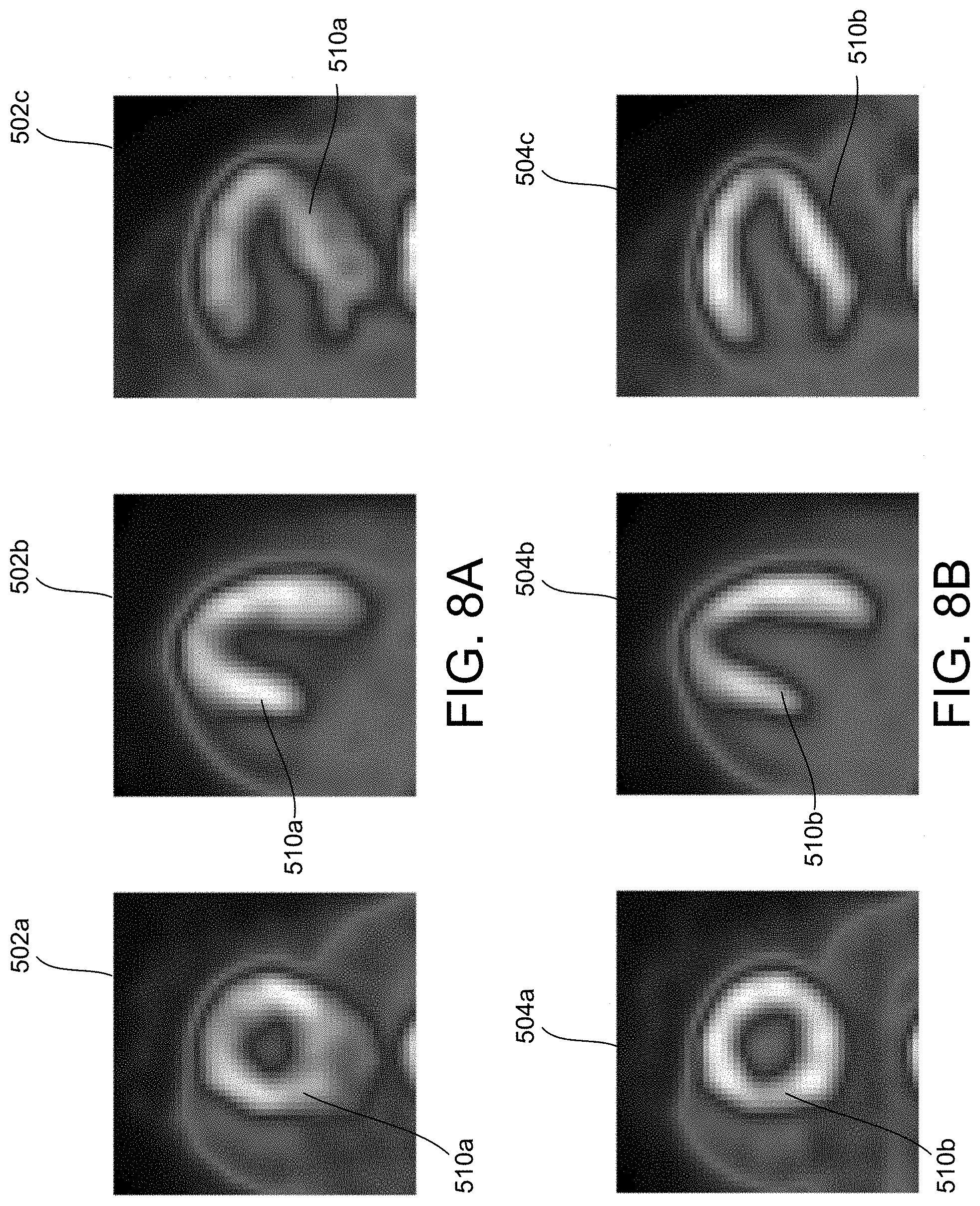
[0016] FIG. 8A illustrates a plurality of reconstructed static images generated from imaging data collected during the imaging period illustrated in FIG. 6 using a traditional reconstruction process.
[0017] FIG. 8B illustrates a plurality of reconstructed static images generated from the imaging data collected during the imaging period illustrated in FIG. 6, in accordance with some embodiments.
[0018] FIG. 9A is a chart illustrating an imaging procedure having an imaging period including non-periodic movement of an organ, in accordance with some embodiments.
[0019] FIG. 9B a plurality of reconstructed static images generated from imaging data collected during the imaging period illustrated in FIG. 9A using a traditional reconstruction process.
[0020] FIG. 9C illustrates a plurality of reconstructed static images generated from the imaging data collected during the imaging period illustrated in FIG. 9A, in accordance with some embodiments.
[0021] FIG. 10A illustrates a plurality of static images of an organ generated using a method of motion correction, in accordance with some embodiments.
[0022] FIG. 10B illustrates a polar image generated from the plurality of static images of FIG. 10A, in accordance with some embodiments.
DETAILED DESCRIPTION
[0023] This description of the exemplary embodiments is intended to be read in connection with the accompanying drawings, which are to be considered part of the entire written description.
[0024] Various embodiments of the present disclosure address the foregoing challenges associated with generating diagnostic PET images from data sets having non-periodic movement. In some embodiments, a plurality of four-dimensional volumetric images are generated from imaging data for a predetermined imaging period. Each four-dimensional volumetric image includes target tissue. A motion vector offset is determined for each of the plurality of four-dimensional volumetric images. The motion vector offsets are determined using target tracking data generated for the target tissue over a time period associated with the four-dimensional volumetric image. Corrected imaging data is generated from the first set of imaging data and the motion vector offsets and at least one static reconstruction image including the target tissue during the imaging period is generated from the corrected imaging data.
[0025] FIG. 1 illustrates one embodiment of a nuclear imaging detector 100. The nuclear imaging detector 100 includes a scanner for at least a first modality 112 provided in a first gantry 116a. The first modality 112 includes a plurality of detectors 50 configured to detect an annihilation photon, gamma ray, and/or other nuclear imaging event. In various embodiments, the first modality 112 is a PET detector. A patient 117 lies on a movable patient bed 118 that may be movable between a gantry. In some embodiments, the nuclear imaging detector 100 includes a scanner for a second imaging modality 114 provided in a second gantry 116b. The second imaging modality 114 can be any suitable imaging modality, such as, for example, computerized tomography (CT), single-photon emission tomography (SPECT) and/or any other suitable imaging modality.
[0026] Scan data from the first modality 112 is stored at one or more computer databases 140 and processed by one or more computer processors 150 of a computer 130. The graphical depiction of computer 130 in FIG. 1 is provided by way of illustration only, and computer 130 may include one or more separate computing devices. The imaging data sets can be provided by the first modality 112 and/or may be provided as a separate data set, such as, for example, from a memory coupled to the computer 130. The computer 130 can include one or more processing electronics for processing a signal received from one of the plurality of detectors 50.
[0027] FIG. 2A illustrates a plurality of static images 200a-200e of a target organ 202, such as a heart. The plurality of static images 200a-200e are generated for a predetermined imaging period, for example, using the nuclear imaging detector 100. During the PET imaging procedure, movement, discomfort, and/or physiological reactions of the patient can result in non-periodic movement within the data. When non-periodic movement is present, significant artefacts and/or motion blur can occur. For example, the plurality of static images 200a-200e include significant motion blur caused by the non-periodic motion of the patient during imaging. As shown in FIG. 2B, a polar image 204 of the target organ 202 generated from the plurality of static images 200a-200e also includes significant artefacts 206a-206b as a result of the non-periodic motion. The non-periodic motion results in static images 200a-200e and a polar image 204 of a non-diagnostic quality, i.e., the images 200a-200e, 204 cannot be used for diagnosing defects or other issues in the target organ 202, resulting in the need to do additional diagnostic imaging of the patient and exposing the patient to additional radiation and discomfort.
[0028] In some embodiments, systems and methods of motion correction are applied to PET imaging data to correct motion blue and/or artefacts introduced by non-periodic movement. FIG. 3 is a flowchart 300 illustrating a method of non-periodic motion correction for PET images, in accordance with some embodiments. The method 300 is configured to identify and track the position of a target organ 204, such as a heart, during reconstruction of diagnostic images to allow removal and/or minimization of non-periodic movement and related artefacts. The method 300 allow generations of diagnostic images from image data that traditionally produces non-diagnostic images, such as, for example, the PET image data associated with the static images 200a-200e in FIG. 2A.
[0029] At step 302, PET imaging data is received by a system, such as, for example, the computer 130. The imaging data can include PET image data for each detection event detected by an imaging modality, such as the first modality 112, during a nuclear imaging procedure. In some embodiments, the imaging data is generated and provided to the system in real-time (e.g., immediately provided from the imaging modality to the system). In other embodiments, the imaging data is generated by the imaging modality during an imaging period and is processed by the system during a later image generation period. In some embodiments, the image data is provided in a listmode format, although it will be appreciated that the data can be provided in any format readable by the system and converted into a listmode format.
[0030] At step 304, a plurality of volumetric images are generated directly from the listmode data 402. For example, as illustrated in FIG. 4, the listmode data 402 includes a plurality of data points each including a first detector identifier (A), a second detector identifier (B), and time-of-flight (TOF), i.e., {(A.sub.1, B.sub.1, TOF.sub.1); (A.sub.2, B.sub.2, TOF.sub.2) . . . (A.sub.n, B.sub.n, TOF.sub.n)}. The first detector identifier (A) and the second detector identifier (B) correspond to detectors 404a, 404b that each detect an annihilation event. Using the detector identifiers and the time-of-flight, the system (such as computer 130) identifies a position 406, or voxel, for the annihilation event. The system generates static volumetric images including each annihilation event in the listmode data 402 over a predetermined diagnostic period, e.g., a four-dimensional volumetric images 408a, 408b (or frames). Each four-dimensional volumetric image 408a, 408b includes three spatial dimensions (x, y, z) and a temporal dimension (t) corresponding to the predetermined time period selected from the predetermined diagnostic period.
[0031] In some embodiments, the temporal dimension t includes 1 second incremental intervals, although it will be appreciated that shorter and/or longer temporal dimensions can be selected. For example, in some embodiments, a first four-dimensional volumetric image is generated for a first time period (e.g., 0-1 second), a second four-dimensional volumetric image is generated for a second time period (e.g., 1-2 seconds), and an nth four-dimensional volumetric image is generated for an nth time period (e.g., (n-1)-n seconds). In some embodiments, the total number of volumetric images generated is equal to the total imagine period (t.sub.total) divided by the temporal dimension increment t, e.g., 1 second, 2 seconds, 0.5 seconds, etc. The predetermined diagnostic period can include an entire imaging procedure and/or a portion of an imaging procedure excluding non-diagnostic imaging such as an ingestion and/or diffusion period prior to a tracer being distributed to target tissue.
[0032] At step 306, a dynamic image of the target tissue is generated for the predetermined diagnostic period. A single continuous dynamic image is generated for the entire predetermined diagnostic period and/or a plurality of dynamic images for portions of the predetermined diagnostic period can be generated. In some embodiments, the dynamic image is generated using imaging data generated by a second imaging modality 114, such as a CT imaging modality. The second set of imaging data is generated simultaneously with the set of PET imaging data. The position of a target tissue is identified within the dynamic image using one or more known target identification processes. For example, in various embodiments, the identification of the target tissue can include, but is not limited to, organ finding using a matched filter for acquisition and normalized cross-correlation for tracking. In some embodiments, a center of the target tissue is identified within the dynamic image.
[0033] At step 308, a motion vector is generated for each four-dimensional volumetric image 408a, 408b using target tracking data generated from the dynamic image (or portion of the dynamic image) corresponding to the temporal dimension t of the selected four-dimensional volumetric image 408a, 408b. For example, in some embodiments, motion and position information from the dynamic image is used to identify the target tissue 410 and/or a center point 412 of the target tissue 410 within each four-dimensional volumetric image 408b, as shown in FIG. 5. Although embodiments are illustrated and discussed including translational tracking of target tissue 410, it will be appreciated that any type of movement, such as translational, rotational, skew, non-rigid transformations, etc. may be tracked and used to generate a motion vector.
[0034] Motion and position information generated from the dynamic image is referenced to each image in the plurality of volumetric images to generate a set of motion vectors for the selected diagnostic period within the listmode data set 402. FIG. 6 is a chart 416 illustrating motion vector offsets 418 for the listmode data 402. The greater the offset 418, the greater the non-periodic movement of the target tissue 410 during the temporal period t of the corresponding four-dimensional volumetric image 408b. In some embodiments, a non-diagnostic portion 422 of the listmode data 402 corresponding to ingestion and diffusion of a tracer molecule is ignored (e.g., not used for diagnostic imaging), although it will be appreciated that additional target tracking and/or diagnostic procedures may be performed that include the ingestion and/or diffusion periods. For example, during early phases of a cardiac scan, the signature of a target organ (i.e., target tissue) changes. In some embodiments, motion tracking through the changes in the target tissue can be tracked and motion correction applied according to the embodiments disclosed herein.
[0035] At step 310, corrected data including axial plane shifts (or other motion correction shifts) corresponding to the motion vector offsets 418 is generated for the listmode data 402. In some embodiments, the plane shifts correspond to discrete shift values on a predetermined axis, such as a z-axis. FIG. 7 is a chart 450 illustrating a plurality of discrete shifts 452 applied to the listmode data 402 during generation of corrected data from the listmode data 402. For example, in some embodiments, a discrete shift value is applied to one or more voxels within the temporal period t to correct a position of the voxel during grouping and reconstruction. In some embodiments, the corrected data is generated using only a predetermined diagnostic portion 420 of the imaging period. In some embodiments, pre-processing of the listmode data 402 can be applied prior to generation of the corrected imaging data, such as, for example, correction for random coincidences, estimation and subtraction of scattered photons, detector dead-time correction, and/or detector-sensitivity correction.
[0036] At step 312, one or more reconstructed static images are generated from the corrected imaging data. The reconstruction can be generated according to known methods for generating PET diagnostic images from the corrected imaging data, such as, for example, filtered back projection, statistical-likelihood based-approaches (e.g., Shepp-Vargi construction), Bayesian constructions, and/or any other suitable method of generating static PET reconstruction images from the corrected imaging data.
[0037] In some embodiments, the method 300 results in the removal of artefacts, such as artefacts 206a-206b illustrated in FIG. 2B, and allows generation of diagnostic-quality reconstructed images from traditionally non-diagnostic listmode data 402. For example, the listmode data 402 includes significant non-periodic motion, such as, for example, as highlighted by box 440 in FIG. 6. FIG. 8A illustrates a plurality of static images 502a-502c of the target tissue 510a generated from the listmode data 402 using traditional methods. As shown in FIG. 8A, the static images 502a-502c have significant motion blur and artefacts such that the images are of non-diagnostic quality and cannot be used for patient diagnosis. FIG. 8B illustrates reconstructions of the target tissue 510b generated from the listmode data 402 using the method 100 of motion correction discussed in conjunction with FIGS. 3-7. As can be seen in FIG. 8B, the motion blur and artefacts of each static image 504a-504c has been eliminated and/or minimized as compared to the static images 502a-502c generated using a non-motion corrected data. The motion corrected static images 504a-504c are of diagnostic quality and can be used in patient diagnosis.
[0038] Similarly, FIG. 9A is a chart 516 illustrating motion vector offsets 518 for listmode PET data including non-periodic organ creep or movement during a diagnostic period 420a, for example, as highlighted by box 519. Organ creep occurs due to relaxation of one or more muscles during an imaging period. As the one or more muscles relax, the position of the organ within the patient shifts. This movement is non-periodic and results in distortion of a reconstructed image due to the change in position of the organ during imaging. FIG. 9B illustrates a plurality of static images 522a-522c of target tissue 520a generated by a traditional reconstruction from the listmode data associated with FIG. 9A using traditional methods. As shown in FIG. 9B, the traditional reconstruction produces static images having artefacts due to organ creep of the target tissue 520a. Although the images are of diagnostic quality, artefacts in the images 522a-522c can result in incorrect or missed diagnosis. FIG. 9C illustrates a plurality of static images 524a-524c of the target tissue 520b generated from the listmode PET data of chart 516 according to the methods disclosed herein. As shown in FIG. 9C, the artefacts of the traditional static images 522a-522c are removed, the edges of the target tissue 520b are more defined, and the diagnostic quality of the images 524a-524c is increased over a traditional static image 522a-522c.
[0039] FIGS. 10A and 10B illustrate the scan data of FIGS. 2A and 2B, respectively, after undergoing a motion correction method as disclosed herein. As shown in FIG. 10B, the polar image 210 generated from the plurality of motion corrected static images 208a-208e does not contain any of the defects 206a-206b included in the original polar image 204. By applying the methods and systems disclosed herein, a diagnostic images 208a-208e, 210 can be generated from data that traditionally generated only non-diagnostic images.
[0040] The apparatuses and processes are not limited to the specific embodiments described herein. In addition, components of each apparatus and each process can be practiced independent and separate from other components and processes described herein.
[0041] The previous description of embodiments is provided to enable any person skilled in the art to practice the disclosure. The various modifications to these embodiments will be readily apparent to those skilled in the art, and the generic principles defined herein may be applied to other embodiments without the use of inventive faculty. The present disclosure is not intended to be limited to the embodiments shown herein, but is to be accorded the widest scope consistent with the principles and novel features disclosed herein.
* * * * *
D00000
D00001
D00002
D00003
D00004
D00005
D00006
D00007
D00008
D00009
D00010
D00011
XML
uspto.report is an independent third-party trademark research tool that is not affiliated, endorsed, or sponsored by the United States Patent and Trademark Office (USPTO) or any other governmental organization. The information provided by uspto.report is based on publicly available data at the time of writing and is intended for informational purposes only.
While we strive to provide accurate and up-to-date information, we do not guarantee the accuracy, completeness, reliability, or suitability of the information displayed on this site. The use of this site is at your own risk. Any reliance you place on such information is therefore strictly at your own risk.
All official trademark data, including owner information, should be verified by visiting the official USPTO website at www.uspto.gov. This site is not intended to replace professional legal advice and should not be used as a substitute for consulting with a legal professional who is knowledgeable about trademark law.