Vacuum
CHOI; Jae Won ; et al.
U.S. patent application number 16/643436 was filed with the patent office on 2020-06-18 for vacuum. The applicant listed for this patent is Samsung Electronics Co., Ltd. Invention is credited to Jae Won CHOI, Yeon Su KIM.
| Application Number | 20200187739 16/643436 |
| Document ID | / |
| Family ID | 65527826 |
| Filed Date | 2020-06-18 |


| United States Patent Application | 20200187739 |
| Kind Code | A1 |
| CHOI; Jae Won ; et al. | June 18, 2020 |
VACUUM
Abstract
The present disclosure relates to a vacuum cleaner capable of enhancing the convenience of use with an improved handle structure. The vacuum cleaner includes a cleaner main body disposed along a longitudinal direction of a suction nozzle and provided to generate a suction force, and a handle provided on the cleaner main body to be gripped and manipulated by a user, wherein the handle includes a first button provided to select on or off of the cleaner main body, and a second button provided to selectively adjust the suction force.
| Inventors: | CHOI; Jae Won; (Seoul, KR) ; KIM; Yeon Su; (Seoul, KR) | ||||||||||
| Applicant: |
|
||||||||||
|---|---|---|---|---|---|---|---|---|---|---|---|
| Family ID: | 65527826 | ||||||||||
| Appl. No.: | 16/643436 | ||||||||||
| Filed: | August 2, 2018 | ||||||||||
| PCT Filed: | August 2, 2018 | ||||||||||
| PCT NO: | PCT/KR2018/008773 | ||||||||||
| 371 Date: | February 28, 2020 |
| Current U.S. Class: | 1/1 |
| Current CPC Class: | A47L 9/2868 20130101; A47L 9/2857 20130101; A47L 9/325 20130101; A47L 9/32 20130101; A47L 5/28 20130101; A47L 9/14 20130101 |
| International Class: | A47L 9/28 20060101 A47L009/28; A47L 5/28 20060101 A47L005/28; A47L 9/32 20060101 A47L009/32; A47L 9/14 20060101 A47L009/14 |
Foreign Application Data
| Date | Code | Application Number |
|---|---|---|
| Aug 31, 2017 | KR | 10-2017-0110942 |
Claims
1. A vacuum cleaner comprising: a cleaner main body disposed along a longitudinal direction of a suction nozzle and configured to generate a suction force; and a handle provided on the cleaner main body and configured to be gripped and manipulated by a user, wherein the handle includes a first button provided to select on or off of the cleaner main body, and a second button provided to selectively adjust the suction force.
2. The vacuum cleaner according to claim 1, wherein the handle includes a handle grip portion, and a battery mounting portion provided to be in parallel with the handle grip portion.
3. The vacuum cleaner according to claim 2, wherein the second button is disposed on the handle grip portion.
4. The vacuum cleaner according to claim 1, wherein the first button is disposed on the cleaner main body.
5. The vacuum cleaner according to claim 1, wherein the first button is disposed on an upper surface of the cleaner main body.
6. The vacuum cleaner according to claim 1, wherein the second button includes a trigger.
7. The vacuum cleaner according to claim 1, wherein the cleaner main body includes a dust collector disposed along the longitudinal direction of the suction nozzle and configured to separate foreign substances from the air introduced through the suction nozzle.
8. The vacuum cleaner according to claim 1, wherein the cleaner main body includes a motor configured to generate the suction force, and the first button and the second button are connected to the motor.
9. The vacuum cleaner according to claim 7, wherein the cleaner main body includes a filter configured to filter the air passing through the dust collector, and at least one discharge port configured such that the air that has passed through the filter is discharged.
10. The vacuum cleaner according to claim 1, wherein the second button is configured to be movable in the longitudinal direction of the suction nozzle.
11. The vacuum cleaner according to claim 10, wherein the second body includes a button guide configured to guide the second button to be moved horizontally.
12. The vacuum cleaner according to claim 11, further comprising an elastic member disposed between the second button and the button guide.
Description
CROSS-REFERENCE TO RELATED APPLICATIONS
[0001] This application is a 371 of International Application No. PCT/KR2018/008773 filed on Aug. 2, 2018, which claims priority to Korean Patent Application No. 10-2017-0110942 filed on Aug. 31, 2017, the disclosures of which are herein incorporated by reference in their entirety.
BACKGROUND
1. Field
[0002] The present disclosure relates to a vacuum cleaner, and more particularly to a vacuum cleaner capable of enhancing the convenience of use with an improved handle structure.
2. Description of Related Art
[0003] In general, a vacuum cleaner is a device capable of performing cleaning by generating a suction force and sucking foreign substances such as dust together with air and then removing the foreign substances using a dust collector and the like provided inside a main body.
[0004] The vacuum cleaner is mainly classified into a canister type and an upright type. The canister type cleaner includes a main body in which a blower, a dust collector, and the like are mounted, a suction nozzle installed separately from the main body to suck dust from a floor, and a connection pipe to connect the main body and the suction nozzle.
[0005] Therefore, a user performs cleaning while holding a handle installed to the connection pipe and moving the suction nozzle in a direction to be cleaned.
[0006] In particular, the user may operate the vacuum cleaner by pulling the handle of a trigger type with a finger. The user turns the vacuum cleaner on or off by grasping a handle grip with the hand and pulling and releasing a trigger provided at a position where an index finger touches.
[0007] However, the trigger type vacuum cleaner is inconvenient in that the user needs to keep pulling the trigger throughout the cleaning.
[0008] In addition, the trigger type vacuum cleaner is cumbersome in that a button for adjusting the suction intensity of the cleaner is separately provided so that the user needs to adjust the suction intensity by using a hand other than the hand holding the handle, which may be a factor that lowers the cleaning efficiency.
SUMMARY
[0009] The present disclosure is directed to providing a vacuum cleaner capable of enhancing the convenience of use by improving the handle structure.
[0010] Further, the present disclosure is directed to providing a vacuum cleaner capable of enhancing the operability of a user by separately providing an on/off power button for the operation and using a trigger as a function to change the suction intensity.
[0011] One aspect of the present disclosure provides a vacuum cleaner including a cleaner main body disposed along a longitudinal direction of a suction nozzle and configured to generate a suction force, and a handle provided on the cleaner main body and configured to be gripped and manipulated by a user, wherein the handle includes a first button provided to select on or off of the cleaner main body, and a second button provided to selectively adjust the suction force.
[0012] The handle may include a handle grip portion and a battery mounting portion provided to be in parallel with the handle grip portion.
[0013] The second button may be disposed on the handle grip portion.
[0014] The first button may be disposed on the cleaner main body.
[0015] The first button may be disposed on an upper surface of the cleaner main body.
[0016] The second button may include a trigger.
[0017] The cleaner main body may include a dust collector disposed along the longitudinal direction of the suction nozzle and configured to separate foreign substances from the air introduced through the suction nozzle.
[0018] The cleaner main body may include a motor configured to generate the suction force, and the first button and the second button may be connected to the motor.
[0019] The cleaner main body may include a filter configured to filter the air passing through the dust collector and at least one discharge port configured such that the air that has passed through the filter is discharged.
[0020] The second button may be configured to be movable in the longitudinal direction of the suction nozzle.
[0021] The second body may include a button guide configured to guide the second button to be moved horizontally.
[0022] The vacuum cleaner may further include an elastic member disposed between the second button and the button guide.
[0023] Another aspect of the present disclosure provides a vacuum cleaner including a cleaner main body disposed along a longitudinal direction of a suction nozzle and configured to generate a suction force, and a handle provided on the cleaner main body and configured to be gripped and manipulated by a user, wherein the cleaner main body includes a first body provided with a dust collector configured to separate foreign substances from the air introduced through the suction nozzle, a second body connected to the first body and configured such that the handle is provided on at least a portion thereof and a motor to generate the suction force is provided on the other portion thereof, a first button provided on the second body to select on or off of the cleaner main body, and a second button provided on the second body to selectively adjust the suction force.
[0024] The handle may include a handle grip portion and a battery mounting portion extending from the second body to be in parallel with the handle grip portion.
[0025] The second button may be disposed on the handle grip portion.
[0026] The first button may be disposed on an upper surface of the second body.
[0027] The motor may be disposed between the first button and the second button.
[0028] The second button may include a trigger.
[0029] The first button and the second button may be connected to the motor.
[0030] The second body may include a filter configured to filter the air passing through the dust collector and at least one discharge port configured such that the air that has passed through the filter is discharged.
[0031] The vacuum cleaner according to an embodiment of the present disclosure has an effect of improving the operability and convenience of use of a user by separately providing an on/off power button for the operation of the vacuum cleaner and improving the handle structure so that a trigger may be used as a function to change the suction intensity.
BRIEF DESCRIPTION OF THE DRAWINGS
[0032] FIG. 1 is a view illustrating a vacuum cleaner according to an embodiment of the present disclosure.
[0033] FIG. 2 is a view illustrating a main body of the vacuum cleaner according to an embodiment of the present disclosure.
[0034] FIG. 3 is an exploded perspective view illustrating a portion of the main body of the vacuum cleaner according to an embodiment of the present disclosure.
[0035] FIG. 4 is an enlarged perspective view of a portion A in FIG. 1, illustrating a first button of the main body of the vacuum cleaner.
[0036] FIG. 5 is a cross-sectional view taken along line B-B' in FIG. 2.
[0037] FIG. 6 is an enlarged perspective view of a portion C in FIG. 2, illustrating a second button of the main body of the vacuum cleaner.
[0038] FIG. 7 is a cross-sectional view taken along line D-D' in FIG. 1.
[0039] FIG. 8 is a view illustrating an operation of the second button according to an embodiment of the present disclosure.
DETAILED DESCRIPTION
[0040] Hereinafter embodiments of the present disclosure will be described in detail with reference to the accompanying drawings. In this specification, the terms "front end," "rear end," "upper portion," "lower portion," "upper end" and "lower end" used in the following description are defined with reference to the drawings, and the shape and position of each component are not limited by these terms.
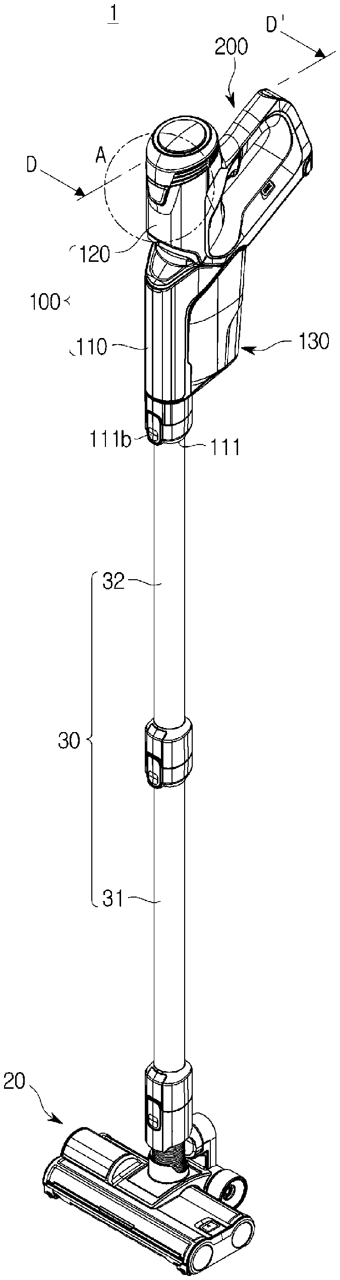
[0041] FIG. 1 is a view illustrating a vacuum cleaner according to an embodiment of the present disclosure.
[0042] As illustrated in FIG. 1, a vacuum cleaner 1 may include a cleaner head 20 configured to suck foreign substances on a surface to be cleaned (not shown) by an air suction force, and a cleaner main body 100 configured to collect the foreign substances sucked through the cleaner head 20.
[0043] The cleaner head 20 may be configured to suck foreign substances such as dust present on the surface to be cleaned while moving in contact with the surface to be cleaned.
[0044] The cleaner main body 100 may include a motor 140, which will be described later, configured to generate a suction force necessary to suck foreign substances present on the surface to be cleaned, and a dust collector 130 configured to receive the foreign substances sucked from the surface to be cleaned. Although the embodiment of the present disclosure illustrates as an example that the dust collector 130 is in a cyclone manner, the present disclosure is not limited thereto, and the kind of the dust collector is not limited.
[0045] The vacuum cleaner 1 may include a suction pipe 30 configured to connect the cleaner head 20 and the cleaning main body 100. At least one of the suction pipe 30 may be provided. The suction pipe 30 may include a first suction pipe 31 connected to the cleaner head 20, and a second suction pipe 32 connected to the first suction pipe 31 and the cleaner main body 100.
[0046] The cleaner main body 100 may include a suction nozzle 111 configured such that the second suction pipe 32 is connected thereto. The suction nozzle 111 is provided such that the first suction pipe 31 and the second suction pipe 32 may be connected thereto. The suction nozzle 111 may include a suction port 111a formed to allow the second suction pipe 32 to be inserted therein. The second suction pipe 32 is inserted into and connected to the suction nozzle 111, so that the suction nozzle 111 is formed in a longitudinal direction of the second suction pipe 32. Although the embodiment of the present disclosure illustrates that the suction nozzle is integrally formed with the cleaner main body as an example, the present disclosure is not limited thereto. For example, the suction nozzle may be separately provided and connected to the cleaner main body.
[0047] The suction nozzle 111 may further include a connector 111b configured to allow the second suction pipe 32 to be detachably connected thereto.
[0048] The cleaner main body 100 may include a handle 200 configured to be gripped by a user. The user may grip the handle 200 and move the cleaner main body 100 and the cleaner head 20 in the front and rear directions.
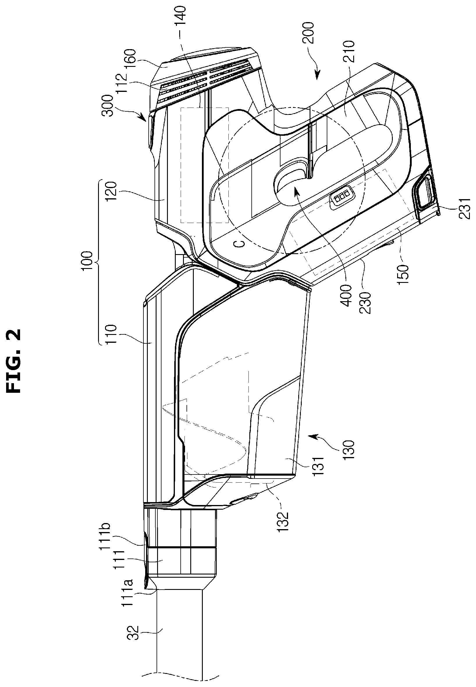
[0049] FIG. 2 is a view illustrating a main body of the vacuum cleaner according to an embodiment of the present disclosure, FIG. 3 is an exploded perspective view illustrating a portion of the main body of the vacuum cleaner according to an embodiment of the present disclosure, FIG. 4 is an enlarged perspective view of a portion A in FIG. 1, illustrating a first button of the main body of the vacuum cleaner, and FIG. 5 is a cross-sectional view taken along line B-B' in FIG. 2.
[0050] As illustrated in FIGS. 2 to 5, the cleaner main body 100 may include a first body 110 provided with the dust collector 130 that separates foreign substances from the air introduced through the suction nozzle 111, and a second body 120 connected to the first body 110.
[0051] The suction nozzle 111 may be provided on one side of the first body 110 and the second body 120 may be rotatably connected to the other side of the first body 110. At least a portion of the second body 120 may form the handle 200.
[0052] The dust collector 130 provided on the first body 110 includes a cyclone 132 and a dust collecting case 131 in which dust and foreign substances separated from air by the cyclone 132 are received. The dust collecting case 131 may be detachably installed on the first body 110.
[0053] A first body cover 110a may be provided at an upper portion of the first body 110, and a dust collecting case 131 may be detachably mounted at a lower portion of the first body cover 110a.
[0054] At least a portion of the second body 120 may form the handle 200, and the other portion of the second body 120 may be provided with a motor 140 to generate a suction force in the dust collector 130.
[0055] The first body 110 and the second body 120 may be arranged in a longitudinal direction of the suction nozzle 111. The dust collector 130 on the first body 110 and the motor 140 on the second body 120 may be arranged side by side in the longitudinal direction of the suction nozzle 111.
[0056] The handle 200 may include a handle grip portion 210 and a battery mounting portion 230 disposed in parallel with the handle grip portion 210. The handle grip portion 210 and the battery mounting portion 230 may be provided on the second body 120.
[0057] A second body cover 120a is provided at an upper portion of the second body 120. The second body cover 120a is provided to be detachable from the second body 120. A motor mounting portion 121 to receive the motor 140 and the fan 141 is provided at the upper portion of the second body 120.
[0058] The motor mounting portion 121 may be provided inside the second body 120. A rear cover 160 may be provided in the rear of the second body 120. The rear cover 160 may be detachably provided in the rear of the second body 120. The rear cover 160 may include a filter 170 therein. The filter 170 may be configured to filter the air passing through the dust collector 130. The filter 170 may include a HEPA filter.
[0059] The second body 120 may include a discharge port 112 provided to allow the air moving through the motor 140 and the fan 141 to be discharged to the outside. The discharge port 112 may be formed on the rear cover 160 to discharge the air that has passed through the filter 170. At least one of the discharge port 112 may be provided. Although the embodiment of the present disclosure illustrates that the discharge port 112 is provided to have three slits on opposite sides of the rear cover 160, respectively, as an example, the present disclosure is not limited thereto.
[0060] The second body 120 may be provided with a filter mounting portion 122 to mount the filter 170 thereon. The filter mounting portion 122 may be disposed in the rear of the second body 120 and may be covered by the rear cover 160.
[0061] The handle grip portion 210 and the battery mounting portion 230 are formed to have a predetermined inclination from the second body 120 and the second body cover 120a. The handle grip portion 210 and the battery mounting portion 230 are provided at a lower portion of the second body 120. The handle grip portion 210 and the battery mounting portion 230 may be disposed in parallel with each other. Although the embodiment of the present disclosure illustrates as an example that the handle grip portion is disposed in the rear of the second body and the battery mounting portion is in the front of the second body, the present disclosure is not limited thereto.
[0062] A battery 150 may be detachably received in the battery mounting portion 230. A battery mounting portion cover 231 on which the battery 150 is detachably provided may be installed on a lower surface of the second body 120. The battery 150 may be inserted in an upward direction from the bottom of the second body 120 to be mounted in the battery mounting portion 230.
[0063] The second body 120 may be provided with a first button 300 and a second button 400 configured to control the operation of the cleaner main body 100.
[0064] The first button 300 may be configured to select on or off of the cleaner main body 100. The second button 400 may be configured to manipulate a suction force of the cleaner main body 100. The first button 300 and the second button 400 may be connected to the motor 140. The first button 300 may be disposed on the second body cover 120a. The first button 300 may include a push manner. The first button 300 may be connected to the motor 140 or the battery 150 through a switch 330. The first button 300 may be positioned above the second button 400.
[0065] The second button 400 may be disposed on the handle grip portion 210 of the second body 120. The second button 400 may include a trigger switch. The second button 400 may be manipulated by an index finger of the user.
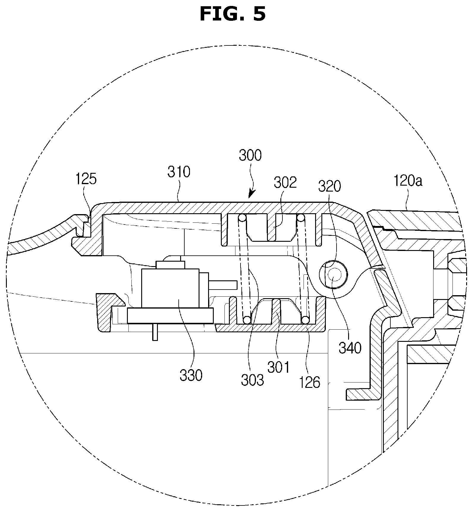
[0066] The first button 300 may be disposed on the second body cover 120a. A first button installing portion 125 to install the first button 300 is formed on the second body cover 120a. The first button installing portion 125 may be formed in a shape corresponding to the first button 300.
[0067] The first button 300 may include a first button cover 310 configured to be pressed by a user to perform an on or off operation of the vacuum cleaner 1. A first hinge portion 320 may be provided on the first button cover 310. The first hinge portion 320 may be formed on opposite side surfaces of a rear end of the first button cover 310. The first hinge portion 320 may include a protrusion formed to protrude.
[0068] A switch mounting portion 126 and a second hinge portion 340 may be provided at the first button installing portion 125 of the second body cover 120a. The second hinge portion 340 may be provided at a position corresponding to the first hinge portion 320 of the first button cover 310. The second hinge portion 340 may include a groove.
[0069] The first button 300 may be installed on the first button installing portion 125 of the second body 120 such that one side thereof is rotatably supported by the first hinge portion 320 and the second hinge portion 340. The switch 330 provided below the first button 300 is installed on the switch mounting portion 126. A spring 303 may be provided between the switch mounting portion 126 and the first button 300 to elastically support the first button 300. A first spring guide 301 and a second spring guide 302 for guiding the spring 303 may be provided on a lower surface of the first button cover 310 and the switch mounting portion 126. The first spring guide 301 and the second spring guide 302 are disposed to face each other.
[0070] Although the embodiment of the present disclosure illustrates as an example that the first button 300 is a push manner, the present disclosure is not limited thereto. For example, the first button may be provided to be movable in a slide manner.
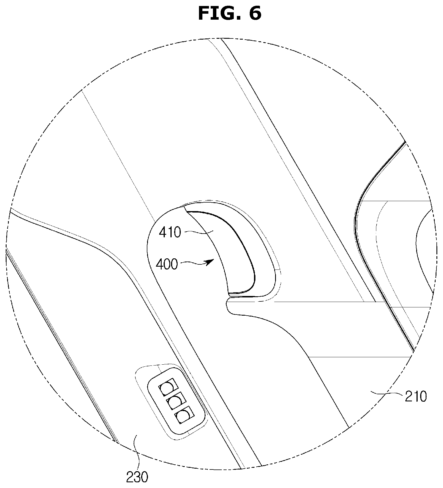
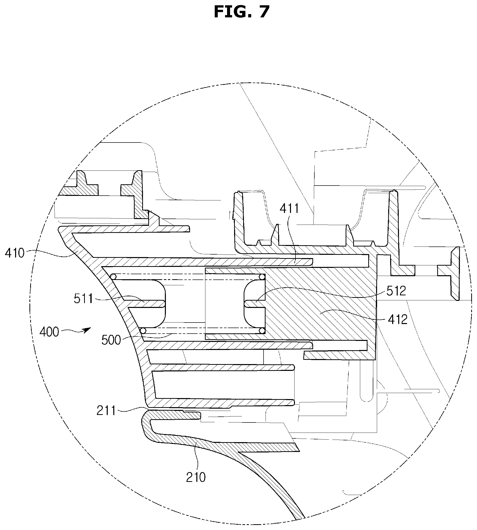
[0071] FIG. 6 is an enlarged perspective view of a portion C in FIG. 2, illustrating a second button of the main body of the vacuum cleaner, FIG. 7 is a cross-sectional view taken along line D-D' in FIG. 1, and FIG. 8 is a view illustrating an operation of the second button according to an embodiment of the present disclosure.
[0072] As illustrated in FIGS. 6 to 8, the second button 400 may be provided to allow the suction force of the cleaner main body 100 to be adjusted.
[0073] The second button 400 may be connected to the motor 140. The second button 400 may be disposed on the handle grip portion 210 of the second body 120. The second button 400 may be manipulated by the index finger of the user.
[0074] The second button 400 may include a second button cover 410 formed in a round shape so that the index finger of the user may be wrapped. The second button cover 410 is provided to allow the user to selectively increase or decrease the suction force during the operation of the vacuum cleaner 1.
[0075] The first guide 411 to guide the second button 400 to be moved back and forth is provided on an inner side of the second button cover 410. The first guide 411 is formed to protrude rearward from the inner side of the second button cover 410.
[0076] A second button installing portion 211 to install the second button 400 may be provided on the handle grip portion 210 of the second body 120. The second button installing portion 211 may be formed at an upper portion of the handle grip portion 210. The second button installing portion 211 may be disposed at an upper end portion of an inner surface of the handle grip portion 210.
[0077] The second button installing portion 211 of the second body 120 is provided with a second guide 412 having a shape corresponding to the first guide 411 of the second button 400. The first guide 411 may be guided by the second guide 412 to move the second button 400 in the front and rear directions.
[0078] An elastic member 500 to return the second button 400 may be provided between the second button 400 and the second button installing portion 211. The elastic member 500 may be provided between a rear surface of the second button cover 410 and the second guide 412. The elastic member 500 may elastically support the second button 400 by being supported by a first elastic member guide 511 formed on the rear surface of the second button cover 410 and a second elastic member guide 512 formed on the second guide 412.
[0079] When the vacuum cleaner 1 is to be used, the user may perform cleaning by pressing the first button 300 provided on the second body 120 of the cleaner main body 100 to turn it on and holding the handle grip portion 210 of the handle 200 and then moving the cleaner head 20.
[0080] In addition, the user may selectively increase or decrease the suction force by manipulating the second button 400 provided on the handle grip portion 210.
[0081] The present disclosure has been particularly described with reference to exemplary embodiments. However, it should be understood by those of skilled in the art that various changes in form and details may be made without departing from the spirit and scope of the present disclosure.
* * * * *
D00000
D00001
D00002
D00003
D00004
D00005
D00006
D00007
D00008
XML
uspto.report is an independent third-party trademark research tool that is not affiliated, endorsed, or sponsored by the United States Patent and Trademark Office (USPTO) or any other governmental organization. The information provided by uspto.report is based on publicly available data at the time of writing and is intended for informational purposes only.
While we strive to provide accurate and up-to-date information, we do not guarantee the accuracy, completeness, reliability, or suitability of the information displayed on this site. The use of this site is at your own risk. Any reliance you place on such information is therefore strictly at your own risk.
All official trademark data, including owner information, should be verified by visiting the official USPTO website at www.uspto.gov. This site is not intended to replace professional legal advice and should not be used as a substitute for consulting with a legal professional who is knowledgeable about trademark law.