Route Server For Distributed Routers Using Hierarchical Routing Protocol
Basavaraj; Vijayalaxmi ; et al.
U.S. patent application number 16/210410 was filed with the patent office on 2020-06-11 for route server for distributed routers using hierarchical routing protocol. The applicant listed for this patent is VMware, Inc.. Invention is credited to Vijayalaxmi Basavaraj, Ankur Dubey.
| Application Number | 20200186468 16/210410 |
| Document ID | / |
| Family ID | 70971322 |
| Filed Date | 2020-06-11 |


| United States Patent Application | 20200186468 |
| Kind Code | A1 |
| Basavaraj; Vijayalaxmi ; et al. | June 11, 2020 |
ROUTE SERVER FOR DISTRIBUTED ROUTERS USING HIERARCHICAL ROUTING PROTOCOL
Abstract
Some embodiments provide a method for a computing device that implements a centralized logical routing component of a logical network that handles data traffic between the logical network and an external physical network. The method receives a first routing protocol message from a machine that implements a route server for a distributed logical routing component of the logical network. The first routing protocol message includes (i) a parameter identifying the machine as a route server and (ii) a set of logical network addresses. The method receives a second routing protocol message from the route server that specifies a next hop address for the set of logical network addresses. The method adds a route specifying the next hop address for the set of logical network addresses to a routing table of the centralized logical routing component. The added route has a higher priority than routes received from the external physical network.
| Inventors: | Basavaraj; Vijayalaxmi; (Cupertino, CA) ; Dubey; Ankur; (Santa Clara, CA) | ||||||||||
| Applicant: |
|
||||||||||
|---|---|---|---|---|---|---|---|---|---|---|---|
| Family ID: | 70971322 | ||||||||||
| Appl. No.: | 16/210410 | ||||||||||
| Filed: | December 5, 2018 |
| Current U.S. Class: | 1/1 |
| Current CPC Class: | H04L 45/04 20130101; H04L 45/124 20130101; H04L 45/745 20130101; H04L 45/122 20130101; H04L 45/42 20130101 |
| International Class: | H04L 12/741 20060101 H04L012/741; H04L 12/715 20060101 H04L012/715; H04L 12/717 20060101 H04L012/717; H04L 12/721 20060101 H04L012/721; H04L 12/733 20060101 H04L012/733 |
Claims
1. For a computing device that implements a centralized logical routing component of a logical network that handles data traffic between the logical network and an external physical network, a method comprising: receiving a first routing protocol message from a machine that implements a route server for a distributed logical routing component of the logical network, the first routing protocol message comprising (i) a parameter identifying the machine as a route server and (ii) a set of logical network addresses; receiving a second routing protocol message from the route server that specifies a next hop address for the set of logical network addresses; and adding a route specifying the next hop address for the set of logical network addresses to a routing table of the centralized logical routing component, wherein the added route has a higher priority than routes received from the external physical network.
2. The method of claim 1 further comprising: receiving a data message addressed to an end machine in the logical network; and routing the data message based on the added route in the routing table.
3. The method of claim 2, wherein the data message is received from a router in the external physical network.
4. The method of claim 2, wherein routing the data message based on the added route in the routing table comprises: performing a first logical processing operation on the data message for the centralized routing component to identify the next hop address as a next hop for the data message; and performing a second logical processing operation on the data message for the distributed logical routing component.
5. The method of claim 4, wherein the computing device implements the distributed logical routing component, wherein a plurality of additional computing devices also implement the distributed logical routing component.
6. The method of claim 1, wherein the centralized routing component is one of a plurality of centralized routing components that are each implemented by a different single computing device, wherein the set of centralized routing components and the distributed logical routing component are components of a same logical router of the logical network.
7. The method of claim 1, wherein the first and second routing protocol messages are first and second link state advertisements (LSAs) for the Open Shortest Path First (OSPF) routing protocol.
8. The method of claim 7, wherein the first LSA is a type 1 LSA comprising a header, wherein the parameter that identifies the machine as a route server is a single bit in an options field of the header.
9. The method of claim 7, wherein the second LSA is a type 9 LSA comprising a header and an opaque information field, wherein the next hop address is specified in the opaque information field.
10. The method of claim 9, wherein the header comprises an opaque type field, wherein the opaque type field identifies the second LSA as opaque type 200.
11. A non-transitory machine readable medium storing a program executable by at least one processing unit, the program for implementing a centralized logical routing component of a logical network that handles data traffic between the logical network and an external physical network, the program comprising sets of instructions for: receiving a first routing protocol message from a machine that implements a route server for a distributed logical routing component of the logical network, the first routing protocol message comprising (i) a parameter identifying the machine as a route server and (ii) a set of logical network addresses; receiving a second routing protocol message from the route server that specifies a next hop address for the set of logical network addresses; and adding a route specifying the next hop address for the set of logical network addresses to a routing table of the centralized logical routing component, wherein the added route has a higher priority than routes received from the external physical network.
12. The non-transitory machine readable medium of claim 11, wherein the program further comprises sets of instructions for: receiving a data message addressed to an end machine in the logical network; and routing the data message based on the added route in the routing table.
13. The non-transitory machine readable medium of claim 12, wherein the data message is received from a router in the external physical network.
14. The non-transitory machine readable medium of claim 12, wherein the set of instructions for routing the data message based on the added route in the routing table comprises sets of instructions for: performing a first logical processing operation on the data message for the centralized routing component to identify the next hop address as a next hop for the data message; and performing a second logical processing operation on the data message for the distributed logical routing component.
15. The non-transitory machine readable medium of claim 14, wherein the computing device implements the distributed logical routing component, wherein a plurality of additional computing devices also implement the distributed logical routing component.
16. The non-transitory machine readable medium of claim 11, wherein the centralized routing component is one of a plurality of centralized routing components that are each implemented by a different single computing device, wherein the set of centralized routing components and the distributed logical routing component are components of a same logical router of the logical network.
17. The non-transitory machine readable medium of claim 11, wherein the first and second routing protocol messages are first and second link state advertisements (LSAs) for the Open Shortest Path First (OSPF) routing protocol.
18. The non-transitory machine readable medium of claim 17, wherein the first LSA is a type 1 LSA comprising a header, wherein the parameter that identifies the machine as a route server is a single bit in an options field of the header.
19. The non-transitory machine readable medium of claim 17, wherein the second LSA is a type 9 LSA comprising a header and an opaque information field, wherein the next hop address is specified in the opaque information field.
20. The non-transitory machine readable medium of claim 19, wherein the header comprises an opaque type field, wherein the opaque type field identifies the second LSA as opaque type 200.
Description
BACKGROUND
[0001] Typical physical networks have several physical routers to perform L3 forwarding (i.e., routing). When a first machine wants to send a packet to a second machine located on a different IP subnet, the packet is sent to a router that uses a destination IP address of the packet to determine through which of its physical interfaces the packet should be sent. Larger networks will have multiple routers, such that if one of the routers fails, the packets can be routed along a different path between the first machine and the second machine.
[0002] In logical networks, user-defined data compute nodes (e.g., virtual machines) on different subnets may need to communicate with each other as well. In this case, tenants may define a network for virtualization that includes both logical switches and logical routers. In certain systems, the logical routers may include both distributed logical routers that are implemented across numerous physical forwarding elements and centralized logical routers that are implemented by single physical forwarding elements. Techniques for these logical routers to communicate with each other are desirable.
BRIEF SUMMARY
[0003] Some embodiments of the invention provide a method for implementing a route server for a distributed logical router (or a distributed routing component of a logical router) that uses a hierarchical routing protocol for routing data messages in a logical network. The logical router of some embodiments includes (i) a distributed routing component that is implemented by managed forwarding elements executing on multiple host computers and (ii) one or more centralized routing components that are each implemented on separate host computers at the edge of the logical network. These centralized routing components are responsible for handling data traffic between the logical network and external physical networks.
[0004] In order for the end machines in the logical network to receive data message traffic from the external network, the centralized routing component (also referred to as an edge gateway) of some embodiments learns routes from the distributed routing component, which logically interfaces more directly with the internal logical network. The edge gateways (i) advertise some of the routes from the distributed routing component to routers in the external network and (ii) use these routes to route data messages received from the external network.
[0005] The edge gateways also learn routes from the external network routers. In certain situations, the edge gateways will learn routes for a public Internet Protocol prefix from the external routers that is also used as an internal private subnet in the logical network (in which case the edge gateway would be configured to not advertise the route, but should use the route for internal routing). In certain cases, the hierarchy of the routing protocol will cause the edge gateway to prefer the route learned from the external router to that learned from the distributed routing component.
[0006] Because the distributed routing component is implemented across numerous (e.g., dozens, hundreds, thousands, etc.) of physical host computers, in some embodiments a route server is used to aggregate the routes of the distributed routing component and advertise these routes to the edge gateways. This route server may be implemented as a separate physical device, a virtual machine or other data compute node executing on a host computer (e.g., separately from data compute nodes that are the endpoints of the logical network), etc.
[0007] In order to ensure that the routes advertised by the distributing routing component route server are preferred by the edge gateway over routes received from the external router, in some embodiments the route server sends two types of routing protocol messages to the edge gateway. The first routing protocol message of some includes (i) a parameter that identifies the machine as a route server to the edge gateway and (ii) a set of addresses (prefixes) for the logical network (e.g., subnets of the logical network). These addresses are the addresses for which routes are advertised to the edge gateways.
[0008] The second routing protocol message specifies a next hop address corresponding to the distributed routing component (e.g., an interface of the distributed routing component that interfaces with the edge gateways), and the edge gateway uses this next hop address as the next hop for the set of addresses sent in the first message. Because the first message identifies the source of these routes as a route server, the edge gateways prefer these routes to routes learned from the external router when updating its routing table. Thus, for data messages addressed to the logical network endpoints, the edge gateway routing table will route the messages to the distributed routing component (which may be implemented by a different routing table on the same computing device). For data messages addressed to other addresses not in the logical network (e.g., external addresses), the edge gateway will still route the packets to the external routers.
[0009] One hierarchical routing protocol used in some embodiments is Open Shortest Path First (OSPF). In this case, the first routing protocol message is a type 1 Link State Advertisement (LSA), also known as a "router LSA." The router LSA includes an options field in the header, where the parameter that identifies the machine as a route server is a single bit in the options field. In some embodiments, the last bit in the options field is the route server bit. In such embodiments, the second routing protocol message is a type 9 LSA, also known as an "opaque LSA." The opaque LSA includes a header with an opaque type field, and also includes an opaque information field. The next hop address is specified in the opaque information field, and the opaque type field is set to a value that allows the edge gateway to recognize the opaque LSA.
[0010] The preceding Summary is intended to serve as a brief introduction to some embodiments of the invention. It is not meant to be an introduction or overview of all of the inventive subject matter disclosed in this document. The Detailed Description that follows and the Drawings that are referred to in the Detailed Description will further describe the embodiments described in the Summary as well as other embodiments. Accordingly, to understand all the embodiments described by this document, a full review of the Summary, Detailed Description and the Drawings is needed. Moreover, the claimed subject matters are not to be limited by the illustrative details in the Summary, Detailed Description and the Drawing, but rather are to be defined by the appended claims, because the claimed subject matters can be embodied in other specific forms without departing from the spirit of the subject matters.
BRIEF DESCRIPTION OF THE DRAWINGS
[0011] The novel features of the invention are set forth in the appended claims. However, for purposes of explanation, several embodiments of the invention are set forth in the following figures.
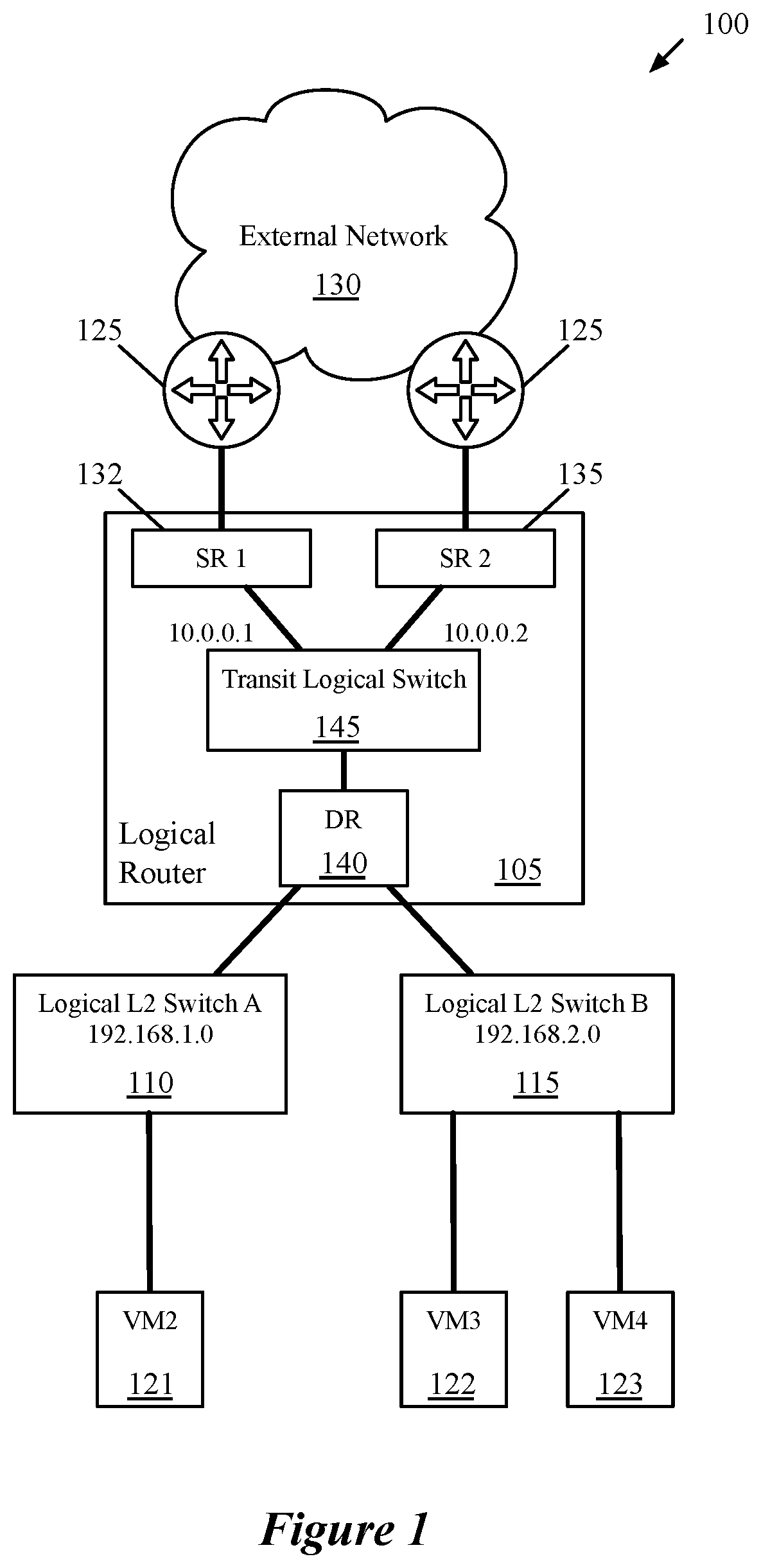
[0012] FIG. 1 conceptually illustrates a management/configuration view of a logical network as designed by a user.
[0013] FIG. 2 conceptually illustrates a physical implementation of the logical network in FIG. 1.
[0014] FIG. 3 illustrates an example of a router link state advertisement (LSA) received by an edge gateway.
[0015] FIG. 4 illustrates the Options field in the header of the LSA of FIG. 3.
[0016] FIG. 5 illustrates an example of an opaque LSA received by the edge gateway.
[0017] FIG. 6 conceptually illustrates a process performed by the edge gateway in some embodiments to process a router LSA.
[0018] FIG. 7 conceptually illustrates a process performed by the edge gateway in some embodiments to process an opaque LSA.
[0019] FIG. 8 conceptually illustrates an electronic system with which some embodiments of the invention are implemented.
DETAILED DESCRIPTION
[0020] Some embodiments of the invention provide a method for implementing a route server for a distributed logical router (or a distributed routing component of a logical router) that uses a hierarchical routing protocol for routing data messages in a logical network. The logical router of some embodiments includes (i) a distributed routing component that is implemented by managed forwarding elements executing on multiple host computers and (ii) one or more centralized routing components that are each implemented on separate host computers at the edge of the logical network. These centralized routing components are responsible for handling data traffic between the logical network and external physical networks.
[0021] FIG. 1 conceptually illustrates a management/configuration view of a logical network 100 of some embodiments. As shown, the logical router 105 is part of a logical network 100 that also includes two logical switches 110 and 115. In this example, each logical switch corresponds to a private subnet, with the first logical switch 110 having the subnet 192.168.1.0/24 and the second logical switch 115 having the subnet 192.168.2.0/24. Each of the logical switches 110 and 115 has a varying number of logical ports to which virtual machines (VMs) 121-123 connect. While shown as VMs in these figures, it should be understood that other types of data compute nodes (e.g., containers, physical servers, etc.) may connect to logical switches in some embodiments. The logical router 105 also connects to external routers 125 in an external physical network 130.
[0022] The network management and control system of some embodiments also defines additional components 132-145 within the logical router 105. These components include multiple centralized routing components (also referred to as service routers, or SRs) 132 and 135, a distributed routing component (DR) 140, and a transit logical switch 145. The distributed routing component 140 includes a south-facing interface for each of the logical switches 110 and 115, and a single north-facing interface to the transit logical switch 145 (used to communicate with the service routers 132 and 135). The service routers 132 and 135 each include a single south-facing interface to the transit logical switch 145 (used to communicate with the distributed routing component 140, as well as each other in certain situations). In addition, in some embodiments, additional logical routers (with distributed and/or centralized routing components of their own) can connect to the distributed routing component 140, with additional logical switches connected to these logical routers.
[0023] Each service router 132 and 135 also corresponds to one or more uplink ports of the logical router 105 for connecting to the external network 130 in some embodiments. Therefore, each of the service routers has a single north-facing interface (though, in other embodiments, a single SR can implement multiple uplink interfaces). The SRs of some embodiments are responsible for delivering services that are not implemented in a distributed fashion (e.g., some stateful services). Even if there are no stateful services configured on the logical router 105, some embodiments use SRs to centralize management of the connection(s) to the external network 130.
[0024] In some embodiments, the management plane generates separate routing information bases (RIBs) for each of the router constructs 132-140. Essentially, the network management and control system treats each of the router constructs 132-140 as a separate logical router with a separate routing table and separate interfaces.
[0025] FIG. 2 illustrates a physical implementation of the logical network 100 according to some embodiments. As shown, each of the VMs 121-123 that couples to one of the logical switches 110 and 115 in the logical network 100 resides on a particular host machine 205. In some embodiments, more than one VM may reside on any given host machine. Managed forwarding elements (MFEs) 210 that execute on these host machines in some embodiments are software virtual switches (e.g., Open vSwitch (OVS), ESX) that operate within hypervisors or other virtualization software (not shown) executing on the host machines. These MFEs 210 perform first-hop switching and routing to implement the logical switches 110 and 115, and the logical router 105, for packets sent by the VMs 121-123 of the logical network 100. As a result, the distributed routing component 140 is implemented across all the MFEs 210 implementing the logical network 100, represented as a dotted rectangle spanning the host machines in FIG. 2.
[0026] The MFEs 210 (or a subset of them) also may implement logical switches (and distributed logical routers) for other logical networks if the other logical networks include VMs or other data compute nodes that reside on the host machines 205 as well. In some embodiments, these other logical networks may be different tenants of a datacenter to which the host machines 210 belong.
[0027] The centralized routing components 132 and 135 each operate on different gateway machines 232 and 235. The gateway machines 232 and 235 are host machines similar to the machines 205, hosting centralized routing components rather than user VMs (in some embodiments, some host machines can host both centralized routing components and user VMs). In some embodiments, the gateway machines 232 and 235 each also include an MFE, in order to handle logical switching as well as routing for the distributed routing component 140. The distributed routing component 140 would then span the gateway machines 232 and 235 accordingly. For instance, packets sent from the external network 130 may be routed by an SR routing table on one of the gateway machines and then subsequently switched and routed (according to the distributed routing component routing table) by the MFE on the same gateway. In other embodiments, the gateway machines execute a datapath (e.g., a DPDK-based datapath) that implements one or more centralized routing components as well as other logical forwarding elements (e.g., logical switches, distributed routing components, etc.).
[0028] The centralized routing components 132 and 135 may also be implemented in a namespace, a virtual machine, or as a VRF in different embodiments. They may operate in an active-active or active-standby mode in some embodiments, depending on whether any stateful services (e.g., firewalls) are configured on the logical router 105. When stateful services are configured, some embodiments require only a single active SR. In some embodiments, the active and standby SRs are provided with the same configuration, but the MFEs 210 are configured to send packets via a tunnel to the active SR (or to the MFE on the gateway machine with the active SR). Only if the tunnel is down will the MFE send packets to the standby gateway.
[0029] In order for VMs in the logical network 100 to receive southbound data message traffic from the external network 130, the SRs 132 and 135 of some embodiments learn routes from the distributed routing component 140 of the logical router 105, which logically interfaces directly with the internal logical network via its south-facing interfaces. In some embodiments, each of the gateway hosts 232 and 235 also executes a routing protocol application (e.g., as a daemon), which receives routing protocol packets sent to the SR and processes these packets in order to modify the SR routing table. In such embodiments, operations attributed below to the SR (e.g., to process routing protocol messages or generate routing protocol messages in order to advertise routes) may instead be performed by the routing protocol application executing alongside the SR.
[0030] The SRs (i) advertise some of the routes from the distributed routing component 140 to the routers 125 in the external network and (ii) use these routes to route data messages received from the external network 130. Route advertisement from centralized routing components to external network routers is explained in further detail in U.S. Pat. Nos. 10,075,363, 10,038,628, and 9,590,901, which are incorporated herein by reference.
[0031] The SRs 132 and 135 also learn routes from the external network routers 125. In certain situations, the SRs 132 and 135 will learn routes for a public Internet Protocol prefix from the external routers 125 that is also used as an internal private subnet in the logical network 100 (in which case the SR would be configured to not advertise the route, but still should use the route for internal routing). However, in certain cases, the hierarchy of the routing protocol will cause the SR to prefer the route learned from the external router 125 to that learned from the DR 140. In some embodiments, the SRs 132 and 135 each use a local database to store information associated with each route, including the source from which the route was received.
[0032] Because the distributed routing component 140 is potentially implemented across numerous (e.g., dozens, hundreds, thousands, etc.) of physical host computers 205, in some embodiments a route server 240 (RS) is used to aggregate the routes of the distributed routing component and advertise these routes to the edge gateways. This route server may be implemented in some embodiments as a separate physical device, a virtual machine or other data compute node executing on a host computer (e.g., separately from data compute nodes that are the endpoints of the logical network), etc. For example, in FIG. 2 the route server 240 is shown as executing (e.g., as a VM) on one of the host machines 205 alongside VM3 123. In other embodiments, the route server is implemented by a network controller.
[0033] In order to ensure that the routes advertised by the route server 240 are preferred by the SRs 132 and 135 over routes received from the external routers 125, in some embodiments the route server sends two types of routing protocol messages to the SRs. The first routing protocol message of some embodiments includes (i) a parameter that identifies the machine 240 as a route server to the SRs and (ii) a set of addresses (prefixes) for the logical network 100 (e.g., subnets of the logical network). These addresses are the addresses for which routes are advertised to the SRs.
[0034] The second routing protocol message specifies a next hop address corresponding to the distributed routing component 140 (e.g., a north-facing interface of the DR that interfaces with the SRs, or in some embodiments via the corresponding interface of the transit logical switch 145), and the SR uses this next hop address as the next hop for the set of addresses sent in the first message. Because the first message identifies the source of these routes as a route server, the SRS can be configured to prefer these routes to routes learned from the external routers 125 when updating its routing table, while otherwise remaining compliant with the routing protocol. Thus, for data messages addressed to end machines in the logical network, the SR routing table will correctly route the messages to the distributed routing component 140 (which may be implemented by a different routing table on the same computing device). For data messages addressed to other addresses not in the logical network (e.g., external addresses), the SRs 132 and 135 will still route these data messages to the external routers 125 in accordance with the default routing protocol hierarchy.
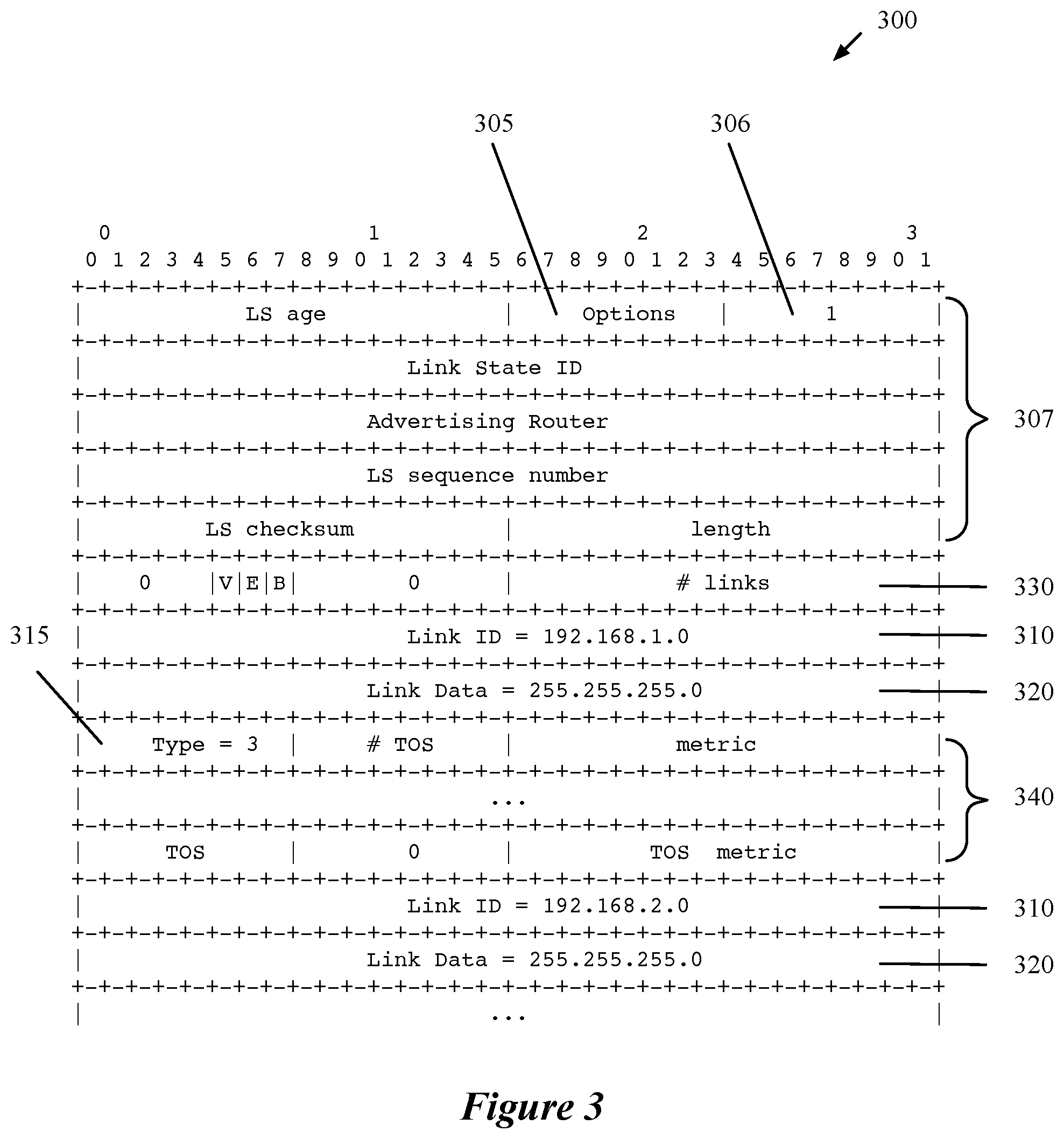
[0035] One hierarchical routing protocol used in some embodiments is Open Shortest Path First (OSPF). In this case, the first routing protocol message is a type 1 Link State Advertisement (LSA), also known as a router LSA. FIG. 3 illustrates an example of such a router LSA 300 received by the edge gateway 132 (i.e., SR1). The router LSA includes an options field 305 and an LSA type field 306 in the header 307. The LSA type field 306 has a value of 1, indicating that this is a type 1 (router) LSA according to the OSPF protocol. After the header 307, the router LSA contains a succession of "Link ID" 310 and "Link Data" 320 fields that each contain an address for advertisement to the edge gateways.
[0036] The options field is expanded for purposes of illustration in FIG. 4. The purpose of the options field is to enable optional capabilities that extend the OSPF protocol. The options field is eight bits long, of which five bits 405 have been assigned by the OSPF protocol. Three bits are unassigned, represented by asterisks (*). These unassigned bits can be used for proprietary purposes, since routers adhering to the OSPF protocol simply ignore any unrecognized bits and process the LSA normally. The parameter 410 that identifies the route server 240 is the last bit in some embodiments, referred to as the route server bit.
[0037] Returning to the router LSA example in FIG. 3, the total number of addresses is tallied in the "# links" field 330 (note that addresses are referred to as links in OSPF terminology). Each link also has a unique identifier in the Link ID field 310, which varies by the type of link, as specified in the "Type" field 315. For example, if the link type is type 3, which is a connection to a subnet of the logical network (a "stub network"), then the link ID is the network/subnet number (e.g. 192.168.1.0).
[0038] The link data field 320 associated with a given link ID also varies by the type of link. For the link type of a stub network, the corresponding link data is the IP address mask (e.g. 255.255.255.0). Additional fields 340 follow, some of which are used by the OSPF algorithm to calculate the optimal path with the shortest cost. After these additional fields, the next link is described with its own link ID, link data, etc.
[0039] In embodiments using the OSPF protocol, the second routing protocol message is a type 9 LSA, also known as an "opaque LSA," which enables extending the OSPF protocol. FIG. 5 illustrates an example of such an opaque LSA 500. The opaque LSA includes an "Opaque Type" field 505 and an LSA type field 506 in the header 507. The LSA type field 506 has a value of 9, indicating that this is a type 9 (opaque) LSA according to the OSPF protocol. After the header 507, the opaque LSA contains an "Opaque Information" field 510.
[0040] The opaque type field 505 specifies a value that allows the edge gateways 132 and 135 to interpret the opaque LSA 500. Values 1-4 are assigned to various OSPF protocol extensions, values 5-127 are unassigned, and values 128-255 are reserved for private (e.g., proprietary) use. For example, in some embodiments, the opaque type value used is 200. The use of an opaque type acts as a filter to reject opaque LSAs from other sources that are not route servers, but which may have also set the same options bit in their router LSAs. It is unlikely that a foreign router would have the same options bit set in its router LSA and the same opaque type in its opaque LSA. The opaque type can therefore be considered a validation of the route server. Opaque LSAs received from a source that is considered a route server due to the options bit, but which have the incorrect opaque type, may be simply ignored.
[0041] The opaque information field 510 is used to specify the specific data relevant to the opaque LSA from the validated route server. In this case, the information is the next hop address to be used for all the link addresses in the router LSA. In this example, the next hop for both subnets linked in the router LSA is the private IP address (10.0.0.1) of the north-facing interface to transit logical switch 145 from SR1 132.
[0042] It should be noted that, as used in this document, the term data packet, packet, data message, or message refers to a collection of bits in a particular format sent across a network. It should be understood that the term data packet, packet, data message, or message may be used herein to refer to various formatted collections of bits that may be sent across a network, such as Ethernet frames, IP packets, TCP segments, UDP datagrams, etc. While the examples above and below refer to data packets, packets, data messages, or messages, it should be understood that the invention should not be limited to any specific format or type of data message.
[0043] FIG. 6 conceptually illustrates a process 600 of some embodiments to process a router LSA. In some embodiments, the process 600 is performed by a centralized routing component of a logical network, to handle a router LSA received from a route server for a distributed routing component of the logical network. The process 600 begins by receiving (at 605) an LSA from a source router. The source router may be an external router, a logical routing component (such as the DR 140), a route server (e.g., a route server for a logical routing component), or any other type of router neighboring the SR under the OSPF protocol.
[0044] After receiving the LSA, the process 600 determines (at 610) the type of LSA from the LSA type field in the LSA header (e.g., the type field 306 shown in FIG. 3). For a router LSA, the value of the router type field should be 1. Other LSA types of the OSPF protocol include type 2 (network LSA), types 3 and 4 (Summary LSAs), type 5 (external LSA), type 6 (multicast LSA), type 7 (NSSA LSA), type 8 (link-local LSA), and types 9-11 (opaque LSAs). If the LSA is not a router LSA, the process 600 processes (at 612) the LSA according to the LSA type specified in the type field, then ends.
[0045] On the other hand, if the LSA is a router LSA (i.e., type 1), the process 600 determines (at 615) whether the route server bit of the router LSA has been set to identify the source of the LSA as a route server (i.e., whether the route server flag is set to 1). As shown in FIGS. 3 and 4, the route server bit is the last bit in the options field of the router LSA header in some embodiments. In other embodiments, other bits (or groups of bits) are set to identify the source of an LSA as a route server.
[0046] If the route server bit has been set, then the process 600 identifies (at 620) the source router as a route server. In some embodiments, the process 600 stores the identification of the route server in an internal database, for reference when it receives an opaque LSA as discussed below. If the route server bit has not been set, then the process 600 does not identify the source router as a route server.
[0047] Next, the process 600 adds (at 625) the links specified in the router LSA to the local routing table (e.g., to the routing table for the centralized routing component). The forwarding address for each link is determined according to the default OSPF protocol hierarchy. If the centralized routing component that receives the router LSA has not yet received any opaque LSAs, the centralized routing component processes the links in the router LSA received from the route server just as it processes links received from another router (e.g., an external router). The process 600 then ends.
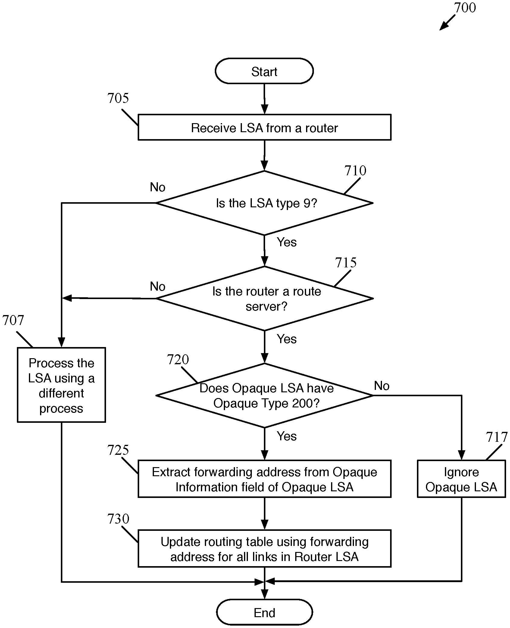
[0048] FIG. 7 conceptually illustrates a process 700 of some embodiments to process an opaque LSA. In some embodiments, the process 700 is performed by a centralized routing component of a logical network, to handle an opaque LSA received from a route server for a distributed routing component of the logical network.
[0049] The process begins by receiving (at 705) an LSA from a source router. The source router may be an external router, a logical routing component (such as the DR 140), a route server (e.g. a route server for a logical routing component), or any other type of router neighboring the SR under the OSPF protocol.
[0050] After receiving the LSA, the process 700 determines (at 710) the type of LSA from the LSA type field in the LSA header (e.g. the type field 506 in the sample opaque LSA illustrated in FIG. 5). For an opaque LSA in OSPF, the value of the router type field should be 9. If the LSA is not an opaque LSA, the process 700 processes (at 707) the LSA according to the LSA type specified in the type field, then ends. For example, if the LSA is a router LSA, then the edge gateway processes the LSA as shown in FIG. 6.
[0051] On the other hand, if the LSA is an opaque LSA, the process determines (at 715) whether the source router is a route server. The SR makes this determination in some embodiments by checking if the source router is identified as a route server in an internal database. For example, the source router would be designated as a route server if the SR previously received a router LSA from the route server with the route server bit set, (e.g., as described above in reference to 615 in FIG. 6).
[0052] If the router is not a route server, the process 700 processes (at 707) the opaque LSA using a different process. For example, the SR may be configured to process opaque LSAs which extend the OSPF protocol in other ways which are unrelated to the route server. The process 700 then ends.
[0053] On the other hand, if the router is a route server, then the process 700 determines (at 720) whether the opaque LSA is the correct opaque type. The opaque LSA type is determined in some embodiments by looking at the opaque type field of the opaque type LSA. For example, in the sample opaque LSA of FIG. 5, the correct opaque type is predefined in the opaque type field 505 as opaque type 200.
[0054] It should be noted that the opaque type is different from the LSA type. The value for the opaque type field, only present in an opaque LSA (e.g. as illustrated in FIG. 5), can range from 1 to 255. According to the OSPF protocol, opaque types 1-127 are reserved for various applications by consensus of the Internet Engineering Task Force (IETF), with types 5-127 unassigned. Opaque types 128-255 are set aside for private use, such as proprietary extensions to the OSPF protocol. If the opaque LSA is not the correct opaque type, then the process 700 ignores (at 717) the opaque LSA.
[0055] In some embodiments, the receipt of an opaque LSA from a route server that is the wrong opaque type occurs when the source router is not actually a route server, even though a previous LSA had been received from the router with the route server bit set. The source router may instead be using the same bit to implement a different feature that is not supported by the SR. Since all routers in an OSPF area receive all LSAs broadcast within the area, in some cases an SR will receive LSAs that were not intended for its consumption (e.g., from external routers). These other routers might also send opaque LSAs with a different opaque type that would be recognized by the intended target of the LSA, but not by the SR. Because the opaque LSA is not the correct type for the SR, the LSA can be safely ignored in compliance with the OSPF protocol. The process 700 then ends.
[0056] If the opaque LSA is the correct opaque type, then the SR knows that it is the intended recipient and knows how to interpret the data within the opaque LSA. The process 700 accordingly extracts (at 725) the forwarding address from the opaque information field of the opaque LSA (e.g., field 510 in the sample opaque LSA 500 in FIG. 5).
[0057] Finally, the process then updates (at 730) the routing table of the SR with the extracted forwarding address for all the links specified in the router LSA received previously from the route server (e.g., as described above with reference to FIG. 6). The process will not update the forwarding address for links specified in router LSAs received from other routers, such as external routers. In some embodiments, the SR stores information associated with each route, such as what source the route was learned from, in an internal database. In such embodiments, the SR would consult that database to determine which routes were learned from the route server and update only those routes with the forwarding address specified in the opaque LSA. The process 700 then ends.
[0058] Many of the above-described features and applications are implemented as software processes that are specified as a set of instructions recorded on a computer readable storage medium (also referred to as computer readable medium). When these instructions are executed by one or more processing unit(s) (e.g., one or more processors, cores of processors, or other processing units), they cause the processing unit(s) to perform the actions indicated in the instructions. Examples of computer readable media include, but are not limited to, CD-ROMs, flash drives, RAM chips, hard drives, EPROMs, etc. The computer readable media does not include carrier waves and electronic signals passing wirelessly or over wired connections.
[0059] In this specification, the term "software" is meant to include firmware residing in read-only memory or applications stored in magnetic storage, which can be read into memory for processing by a processor. Also, in some embodiments, multiple software inventions can be implemented as sub-parts of a larger program while remaining distinct software inventions. In some embodiments, multiple software inventions can also be implemented as separate programs. Finally, any combination of separate programs that together implement a software invention described here is within the scope of the invention. In some embodiments, the software programs, when installed to operate on one or more electronic systems, define one or more specific machine implementations that execute and perform the operations of the software programs.
[0060] FIG. 8 conceptually illustrates an electronic system 800 with which some embodiments of the invention are implemented. The electronic system 800 may be a computer (e.g., a desktop computer, personal computer, tablet computer, server computer, mainframe, a blade computer etc.), phone, PDA, or any other sort of electronic device. Such an electronic system includes various types of computer readable media and interfaces for various other types of computer readable media. Electronic system 800 includes a bus 805, processing unit(s) 810, a system memory 825, a read-only memory 830, a permanent storage device 835, input devices 840, and output devices 845.
[0061] The bus 805 collectively represents all system, peripheral, and chipset buses that communicatively connect the numerous internal devices of the electronic system 800. For instance, the bus 805 communicatively connects the processing unit(s) 810 with the read-only memory 830, the system memory 825, and the permanent storage device 835.
[0062] From these various memory units, the processing unit(s) 810 retrieve instructions to execute and data to process in order to execute the processes of the invention. The processing unit(s) may be a single processor or a multi-core processor in different embodiments.
[0063] The read-only-memory (ROM) 830 stores static data and instructions that are needed by the processing unit(s) 810 and other modules of the electronic system. The permanent storage device 835, on the other hand, is a read-and-write memory device. This device is a non-volatile memory unit that stores instructions and data even when the electronic system 800 is off. Some embodiments of the invention use a mass-storage device (such as a magnetic or optical disk and its corresponding disk drive) as the permanent storage device 835.
[0064] Other embodiments use a removable storage device (such as a floppy disk, flash drive, etc.) as the permanent storage device. Like the permanent storage device 835, the system memory 825 is a read-and-write memory device. However, unlike storage device 835, the system memory is a volatile read-and-write memory, such as random-access memory. The system memory stores some of the instructions and data that the processor needs at runtime. In some embodiments, the invention's processes are stored in the system memory 825, the permanent storage device 835, and/or the read-only memory 830. From these various memory units, the processing unit(s) 810 retrieve instructions to execute and data to process in order to execute the processes of some embodiments.
[0065] The bus 805 also connects to the input and output devices 840 and 845. The input devices enable the user to communicate information and select commands to the electronic system. The input devices 840 include alphanumeric keyboards and pointing devices (also called "cursor control devices"). The output devices 845 display images generated by the electronic system. The output devices include printers and display devices, such as cathode ray tubes (CRT) or liquid crystal displays (LCD). Some embodiments include devices such as a touchscreen that function as both input and output devices.
[0066] Finally, bus 805 also couples electronic system 800 to a network 865 through a network adapter (not shown). In this manner, the computer can be a part of a network of computers (such as a local area network ("LAN"), a wide area network ("WAN"), or an Intranet, or a network of networks, such as the Internet. Any or all components of electronic system 800 may be used in conjunction with the invention.
[0067] Some embodiments include electronic components, such as microprocessors, storage and memory that store computer program instructions in a machine-readable or computer-readable medium (alternatively referred to as computer-readable storage media, machine-readable media, or machine-readable storage media). Some examples of such computer-readable media include RAM, ROM, read-only compact discs (CD-ROM), recordable compact discs (CD-R), rewritable compact discs (CD-RW), read-only digital versatile discs (e.g., DVD-ROM, dual-layer DVD-ROM), a variety of recordable/rewritable DVDs (e.g., DVD-RAM, DVD-RW, DVD+RW, etc.), flash memory (e.g., SD cards, mini-SD cards, micro-SD cards, etc.), magnetic and/or solid state hard drives, read-only and recordable Blu-Ray.RTM. discs, ultra-density optical discs, any other optical or magnetic media, and floppy disks. The computer-readable media may store a computer program that is executable by at least one processing unit and includes sets of instructions for performing various operations. Examples of computer programs or computer code include machine code, such as is produced by a compiler, and files including higher-level code that are executed by a computer, an electronic component, or a microprocessor using an interpreter.
[0068] While the above discussion primarily refers to microprocessor or multi-core processors that execute software, some embodiments are performed by one or more integrated circuits, such as application specific integrated circuits (ASICs) or field programmable gate arrays (FPGAs). In some embodiments, such integrated circuits execute instructions that are stored on the circuit itself.
[0069] As used in this specification, the terms "computer", "server", "processor", and "memory" all refer to electronic or other technological devices. These terms exclude people or groups of people. For the purposes of the specification, the terms display or displaying means displaying on an electronic device. As used in this specification, the terms "computer readable medium," "computer readable media," and "machine readable medium" are entirely restricted to tangible, physical objects that store information in a form that is readable by a computer. These terms exclude any wireless signals, wired download signals, and any other ephemeral signals.
[0070] This specification refers throughout to computational and network environments that include virtual machines (VMs). However, virtual machines are merely one example of data compute nodes (DNCs) or data compute end nodes, also referred to as addressable nodes. DCNs may include non-virtualized physical hosts, virtual machines, containers that run on top of a host operating system without the need for a hypervisor or separate operating system, and hypervisor kernel network interface modules.
[0071] VMs, in some embodiments, operate with their own guest operating systems on a host using resources of the host virtualized by virtualization software (e.g., a hypervisor, virtual machine monitor, etc.). The tenant (i.e., the owner of the VM) can choose which applications to operate on top of the guest operating system. Some containers, on the other hand, are constructs that run on top of a host operating system without the need for a hypervisor or separate guest operating system. In some embodiments, the host operating system isolates the containers for different tenants and therefore provides operating-system level segregation of the different groups of applications that operate within different containers. This segregation is akin to the VM segregation that is offered in hypervisor-virtualized environments, and thus can be viewed as a form of virtualization that isolates different groups of applications that operate in different containers. Such containers are more lightweight than VMs.
[0072] Hypervisor kernel network interface modules, in some embodiments, is a non-VM DCN that includes a network stack with a hypervisor kernel network interface and receive/transmit threads. One example of a hypervisor kernel network interface module is the vmknic module that is part of the ESX hypervisor of VMware Inc.
[0073] One of ordinary skill in the art will recognize that while the specification refers to VMs, the examples given could be any type of DCNs, including physical hosts, VMs, non-VM containers, and hypervisor kernel network interface modules. In fact, the example networks could include combinations of different types of DCNs in some embodiments.
[0074] While the invention has been described with reference to numerous specific details, one of ordinary skill in the art will recognize that the invention can be embodied in other specific forms without departing from the spirit of the invention. In addition, at least one figure conceptually illustrates a process. The specific operations of this process may not be performed in the exact order shown and described. The specific operations may not be performed in one continuous series of operations, and different specific operations may be performed in different embodiments. Furthermore, the process could be implemented using several sub-processes, or as part of a larger macro process. Thus, one of ordinary skill in the art would understand that the invention is not to be limited by the foregoing illustrative details, but rather is to be defined by the appended claims.
* * * * *
D00000
D00001
D00002
D00003
D00004
D00005
D00006
D00007
XML
uspto.report is an independent third-party trademark research tool that is not affiliated, endorsed, or sponsored by the United States Patent and Trademark Office (USPTO) or any other governmental organization. The information provided by uspto.report is based on publicly available data at the time of writing and is intended for informational purposes only.
While we strive to provide accurate and up-to-date information, we do not guarantee the accuracy, completeness, reliability, or suitability of the information displayed on this site. The use of this site is at your own risk. Any reliance you place on such information is therefore strictly at your own risk.
All official trademark data, including owner information, should be verified by visiting the official USPTO website at www.uspto.gov. This site is not intended to replace professional legal advice and should not be used as a substitute for consulting with a legal professional who is knowledgeable about trademark law.