Methods For Assessing Presence Of Electrical, Electronic, And/or Mechanical Faults In Electromechanical Linear Actuators
BORGARELLI; Nicola ; et al.
U.S. patent application number 16/617656 was filed with the patent office on 2020-06-11 for methods for assessing presence of electrical, electronic, and/or mechanical faults in electromechanical linear actuators. The applicant listed for this patent is Umbragroup S.p.A.. Invention is credited to Nicola BORGARELLI, Marco NARDESCHI, Luciano PIZZONI, Antonio TOMASIELLO.
| Application Number | 20200186005 16/617656 |
| Document ID | / |
| Family ID | 60182876 |
| Filed Date | 2020-06-11 |


| United States Patent Application | 20200186005 |
| Kind Code | A1 |
| BORGARELLI; Nicola ; et al. | June 11, 2020 |
METHODS FOR ASSESSING PRESENCE OF ELECTRICAL, ELECTRONIC, AND/OR MECHANICAL FAULTS IN ELECTROMECHANICAL LINEAR ACTUATORS
Abstract
The present disclosure relates to a method of assessing the presence of an electrical, electronic and/or mechanical fault in an electromechanical linear actuator (1), said electromechanical linear actuator (1) comprising a containment structure (2); first and second independent lead nuts (8, 9), each having its own thread and its own thread direction, two electric motors (5A, 5B) disposed in the containment structure (2) and operably connected with said first and second lead nuts (8, 9) to rotate them about said axis of rotation (X); a shaft (6) inserted in said first and second lead nuts (8, 9), a rotation-preventing mechanism (7) operable/active on said shaft (6) to prevent the shaft (6) from rotating about said axis of rotation (X); coupling means (10, 15, 11), configured to mechanically couple said first and second lead nuts (8, 9) with said shaft (6), so that a rotational movement of said first and/or second lead nuts (8, 9) will cause a translation of said shaft (6) along said axis of rotation (X). The method is characterized by comprising the steps of: actuating said two electric motors (5A, 5B) to drive said first and second lead nuts (8, 9) in the same direction of rotation or in opposite directions of rotation; during said step of actuating said two electric motors (5A, 5B), checking whether said shaft (6) translates relative to said containment structure (2).
| Inventors: | BORGARELLI; Nicola; (Foligno (PG), IT) ; PIZZONI; Luciano; (Foligno (PG), IT) ; NARDESCHI; Marco; (Foligno (PG), IT) ; TOMASIELLO; Antonio; (Foligno (PG), IT) | ||||||||||
| Applicant: |
|
||||||||||
|---|---|---|---|---|---|---|---|---|---|---|---|
| Family ID: | 60182876 | ||||||||||
| Appl. No.: | 16/617656 | ||||||||||
| Filed: | May 30, 2018 | ||||||||||
| PCT Filed: | May 30, 2018 | ||||||||||
| PCT NO: | PCT/IB2018/053831 | ||||||||||
| 371 Date: | November 27, 2019 |
| Current U.S. Class: | 1/1 |
| Current CPC Class: | F16H 2025/2075 20130101; F16H 2025/2059 20130101; B64C 13/505 20180101; H02K 7/06 20130101; F16H 25/20 20130101; B64D 2045/0085 20130101 |
| International Class: | H02K 7/06 20060101 H02K007/06; F16H 25/20 20060101 F16H025/20 |
Foreign Application Data
| Date | Code | Application Number |
|---|---|---|
| May 30, 2017 | IT | 102017000058891 |
Claims
1. Method of assessing the presence of an electrical, electronic and/or mechanical fault in an electromechanical linear actuator (1), said electromechanical linear actuator (1), comprising: a containment structure (2); first and second independent lead nuts (8, 9), each having its own thread and its own thread direction, two electric motors (5A, 5B) disposed in the containment structure (2) and operably connected with said first and second lead nuts (8, 9) to rotate them about said axis of rotation (X); a shaft (6) inserted in said first and second lead nuts (8, 9) a rotation-preventing mechanism (7) operable on said shaft (6) to prevent the shaft (6) from rotating about said axis of rotation (X); coupling means (10, 15, 11), which are configured to mechanically couple said first and second lead nuts (8, 9) with said shaft (6), so that a rotational movement of said first and/or second lead nuts (8, 9) will cause a translation of said shaft (6) along said axis of rotation (X); first and second electric brakes (12A, 12B), operable on said first and second lead nuts (8, 9) respectively, to brake their rotation about said axis of rotation (X); command and control electronics for each electric motor and electric brake comprising a plurality of sensors (16-20) arranged in said containment structure (2) operatively connected with the command and control electronics, said plurality of sensors (16-20) being designed to detect the position of the shaft (6) so as to detect its movements along the axis X; said coupling means (10, 15, 11) comprise: an intermediate coupling stage (10) inserted in said first and second lead nuts (8, 9), respective first mechanical connection means (15) for coupling said intermediate coupling stage (10) with each lead nut (8, 9), second mechanical connection means (11); said shaft (6) being fitted into said intermediate coupling stage (10) and being connected with the latter through said second mechanical connection means (11); said method being characterized by the steps of: actuating (23) said two electric motors (5A, 5B) to drive said first and second lead nuts (8, 9) in the same direction of rotation or in opposite directions of rotation; during said step of actuating said two electric motors (5A, 5B), checking (24) via said plurality of sensors (16-20) whether said shaft (6) translates relative to said containment structure (2) and whether said shaft (6) does not translate relative to the containment structure (2); checking (31) whether there is a mechanical failure of the intermediate stage (10) with either of the lead nuts (8, 9), to thereby actuate (32) the two electric motors (5A and 5B) in the same direction of rotation; checking (33) whether there is a mechanical failure of the shaft (6) with the intermediate stage (10), to thereby actuate (34) the two electric motors (5A and 5B) in opposite directions of rotation.
2. A method of assessing the presence of an electrical, electronic and/or mechanical fault in an electromechanical linear actuator (1) as claimed in claim 1, wherein said step of actuating said two electric motors (5A, 5B) has a predetermined actuation interval (T) having a fixed or variable repetition frequency.
3. A method of assessing the presence of an electrical, electronic and/or mechanical fault in an electromechanical linear actuator (1) as claimed in claim 1, comprising, if said shaft (6) does not translate relative to the containment structure, the steps (27) of: checking whether one or both of said two electric motors (5A, 5B) or said control electronics have a breakdown (29); actuating (30) the first and the second electric brakes (12A, 12B) to prevent rotation of said first or said second lead nuts (8, 9) on the side of the faulty motor/electronics.
4. A method of assessing the presence of an electrical, electronic and/or mechanical fault in an electromechanical linear actuator (1) as claimed in claim 1, wherein said shaft (6) is a screw shaft and said second mechanical connection means (11) comprise a nut and screw coupling between said screw shaft (6) and said intermediate coupling stage (10), such that a rotational movement of said first and/or second lead nuts (8, 9) causes a rotational, translational or rototranslational movement of said intermediate coupling stage (10) along said axis of rotation (X) and said intermediate coupling stage (10) in turn causes a translational movement of said screw shaft (6) along said axis of rotation (X).
5. A method of assessing the presence of an electrical, electronic and/or mechanical fault in an electromechanical linear actuator (1) as claimed in claim 1, wherein each of the respective first mechanical connection means (15) comprise a nut and screw coupling.
6. A method of assessing the presence of an electrical, electronic and/or mechanical fault in an electromechanical linear actuator (1) as claimed in claim 1, wherein the thread pitch (6A) of said screw shaft (6) is different from the thread pitch of said first and second lead nuts (8, 9).
7. A method of assessing the presence of an electrical, electronic and/or mechanical fault in an electromechanical linear actuator (1) as claimed in claim 1, wherein the pitch of said thread of said first lead nut (8) is oriented in a direction opposite to the pitch of said thread of said second lead nut (9).
8. A method of assessing the presence of an electrical, electronic and/or mechanical fault in an electromechanical linear actuator (1) as claimed in claim 1, wherein said intermediate coupling stage (10) has: externally, first and second threads (10A, 10B), each being configured to couple with a respective lead nut (8, 9) and internally, a third thread (10C), configured to be coupled with said thread (6A) of said screw shaft (6).
9. A method of assessing the presence of an electrical, electronic and/or mechanical fault in an electromechanical linear actuator (1) as claimed in claim 8, wherein said firs thread (10A) is located proximate to a first terminal end (10') of said intermediate coupling stage (10) and said second thread (10B) is located proximate to a second terminal end (10'') opposite to the first end (10') of said intermediate coupling stage (10).
Description
DESCRIPTION
Field of the Invention
[0001] The present disclosure relates to a method of assessing the presence of an electrical, electronic and/or mechanical fault in an electromechanical linear actuator as defined in the preamble of claim 1.
[0002] Particularly, but without limitation, the actuator is an electromechanical linear actuator for controlling a control surface of an aircraft, a boat or the steering system of a vehicle or similar applications.
Description of Prior Art
[0003] Electromechanical linear actuators are known, which are equipped with command and control electronics, are driven by an electric motor, and have the task of converting the rotary motion of the electric motor into a reciprocating linear motion of a pushing member to control the position of a control surface.
[0004] For this purpose, the electric motor is connected via a reduction apparatus to the pushing member, which is in turn connected to the control surface to control the position that this surface is to assume in response to the controls received from the command and control electronics.
[0005] Usually, the reduction apparatus comprises a lead nut with a screw sliding thereon (or a screw with a lead nut sliding thereon), which in turn is connected to the pushing member and, whereby a rotation-preventing device, only is allowed to the screw (or the lead nut) the only a linear and non-rotational movement of the screw, thereby providing the linear reciprocating motion of the pushing member.
[0006] Such electromechanical linear actuators have been used, for example, to control the secondary control surfaces of an aircraft, such as air brakes, spoilers, flaps, trim tabs, but also to open hatches and other uses requiring low power, speed and responsiveness i.e. for the so-called "non-safety critical" applications.
[0007] However, the reliability of an electromechanical actuator as defined above does not allow it to be used in installations designed to control primary control surfaces of an aircraft, the swash plate of a helicopter, the steering system of a vehicle or the rudder of a ship, i.e. more generally all "safety critical" applications.
[0008] This is because the above described electromechanical actuator is poorly reliable both in its electrical part, i.e. the electric motor, and in the command and control electronics, as well as the possibility of a seizure of the mechanical part (the so-called mechanical "jamming").
[0009] In an attempt to obviate this drawback, architectures have been used which either include two identical actuators that move the same control surface, thereby providing electrical, electronic and mechanical redundancy, but also increasing the weight and complexity of the system, or have a single actuator equipped with a differential gear box, which affords the use of two independent electric motors and two independent electronics to move the same mechanical system.
[0010] U.S. Pat. No. 4,179,944 discloses an exemplary electromechanical linear actuator having two motors directly coupled to a shaft via ball nuts. This electromechanical actuator does not provide enough redundancy to ensure fault tolerance against both mechanical and electrical and electronic faults. This electromechanical actuator only affords detection of two types of mechanical faults, mainly associated with the moving shaft, thereby only providing limited redundancy, especially for mechanical faults occurring between the motor and the shaft. Furthermore, this electromechanical actuator might be problematic in case of electrical and/or electronic fault associated with the electric motors. Such motors should be sized to ensure operation both in a fully operational state and in a failure state, e.g. to overcome torques caused by mechanical faults, when either motor is stalled.
Prior Art Problem
[0011] Nevertheless, the need is increasingly felt to be able to detect electrical, electronic and/or mechanical faults, and particularly "latent failures" of the actuator/s that are part of the above described architectures. Latent failures are known as failures that may occur in a mechanical or electrical/electronic component, in a circuit or in a system, and that have not appeared yet, although the event that triggers them has already occurred, with the architecture still being able to be operated.
[0012] Namely, the above described architectures are tested during scheduled periodic inspections and, if no anomaly is detected, such architectures are deemed to be fully efficient and hence operable. Nevertheless, undetected and/or undetectable failures might occur during use, and reduce efficiency more or less severely, but these failures will be hidden until the next inspection, thereby affecting the safety provided by redundancy.
[0013] This is a serious problem, especially when the electromechanical actuator is employed in safety critical applications.
SUMMARY OF THE INVENTION
[0014] The object of the present invention is to provide a method of assessing the presence of an electrical, electronic and/or mechanical fault in an electromechanical linear actuator that can solve the above described prior art problems,
[0015] This object is fulfilled by a method of assessing the presence of an electrical, electronic and/or mechanical fault in an electromechanical linear actuator, as defined in the annexed claim 1.
Advantages of the Invention
[0016] One embodiment of the present invention provides a method of assessing the presence of electrical, electronic and/or mechanical faults, such as latent failures, in an electromechanical linear actuator of the Fault Tolerant Differential Direct Drive type.
[0017] Furthermore, one embodiment of the present invention provides a method that can identify the type of failure in an electromechanical linear actuator. Particularly, due to the introduction of an intermediate stage between the lead nuts and the shaft, the electromechanical linear actuator ensures greater reliability as compared with the above discussed prior art.
[0018] Furthermore, one embodiment of the present invention provides a method that can identify the type of mechanical failure in the electromechanical linear actuator and can actuate the electric motors to overcome the identified failure. Particularly, the actuator is equipped with a number of sensors that cooperate to identify the type of failure.
BRIEF DETAILS OF THE DRAWINGS
[0019] The characteristics and advantages of the present disclosure will appear from the following detailed description of a possible practical embodiment, illustrated as a non-limiting example in the set of drawings, in which:
[0020] FIGS. 1A and 1B show two possible implementation scenarios for the electromechanical linear actuator, FIG. 1A schematically depicting a primary control surface of an aircraft operated by a single-acting actuator (with a single pushing member projecting out of one side of the actuator) and FIG. 1B schematically depicting a steering assembly of a vehicle operated by a double-acting actuator (with two pushing member projecting out of both sides of the actuator);
[0021] FIG. 2 shows a sectional view of the electromechanical linear actuator according to a first embodiment;
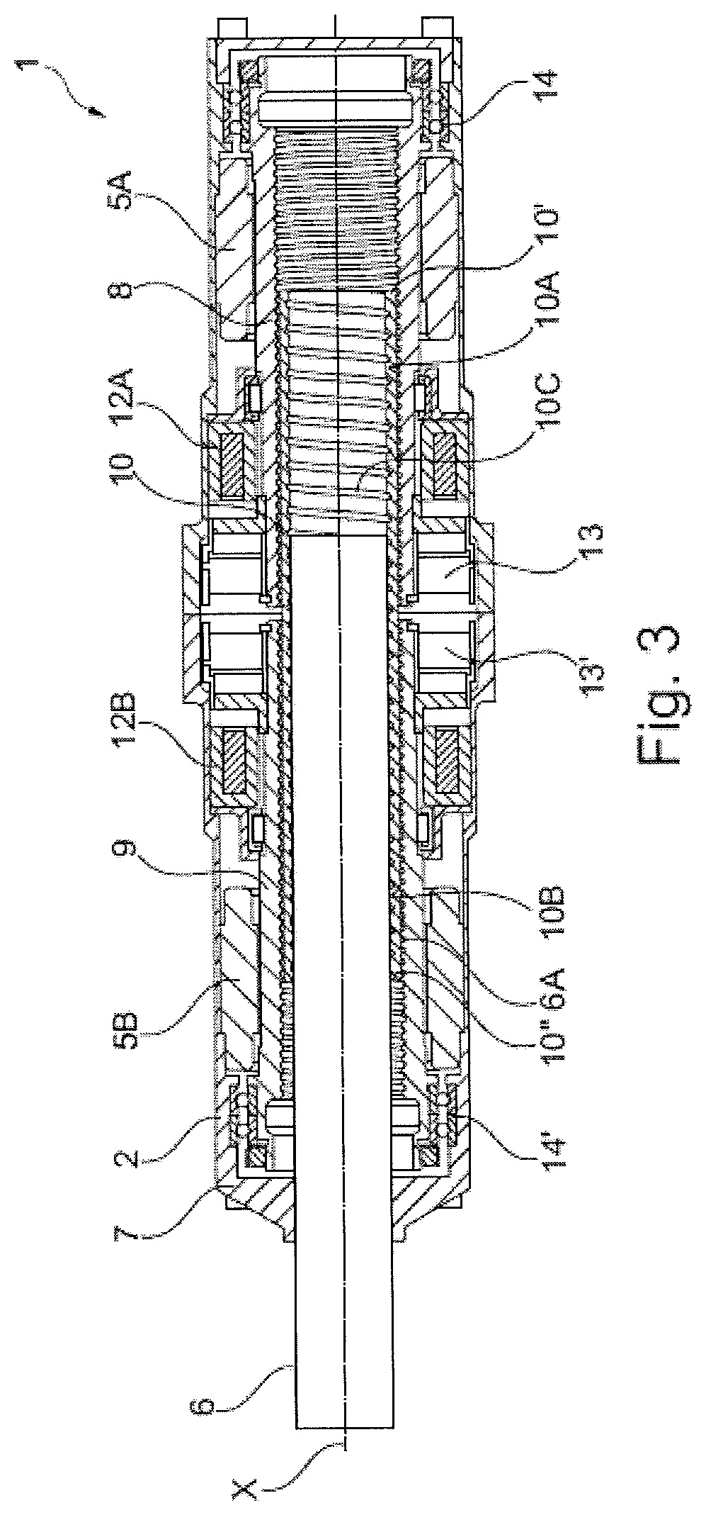
[0022] FIG. 3 shows another sectional view of the first embodiment of the present invention, depicted more schematically to highlight the characteristic features of the actuator;
[0023] FIG. 4 shows a sectional view of the electromechanical linear actuator according to a second embodiment;
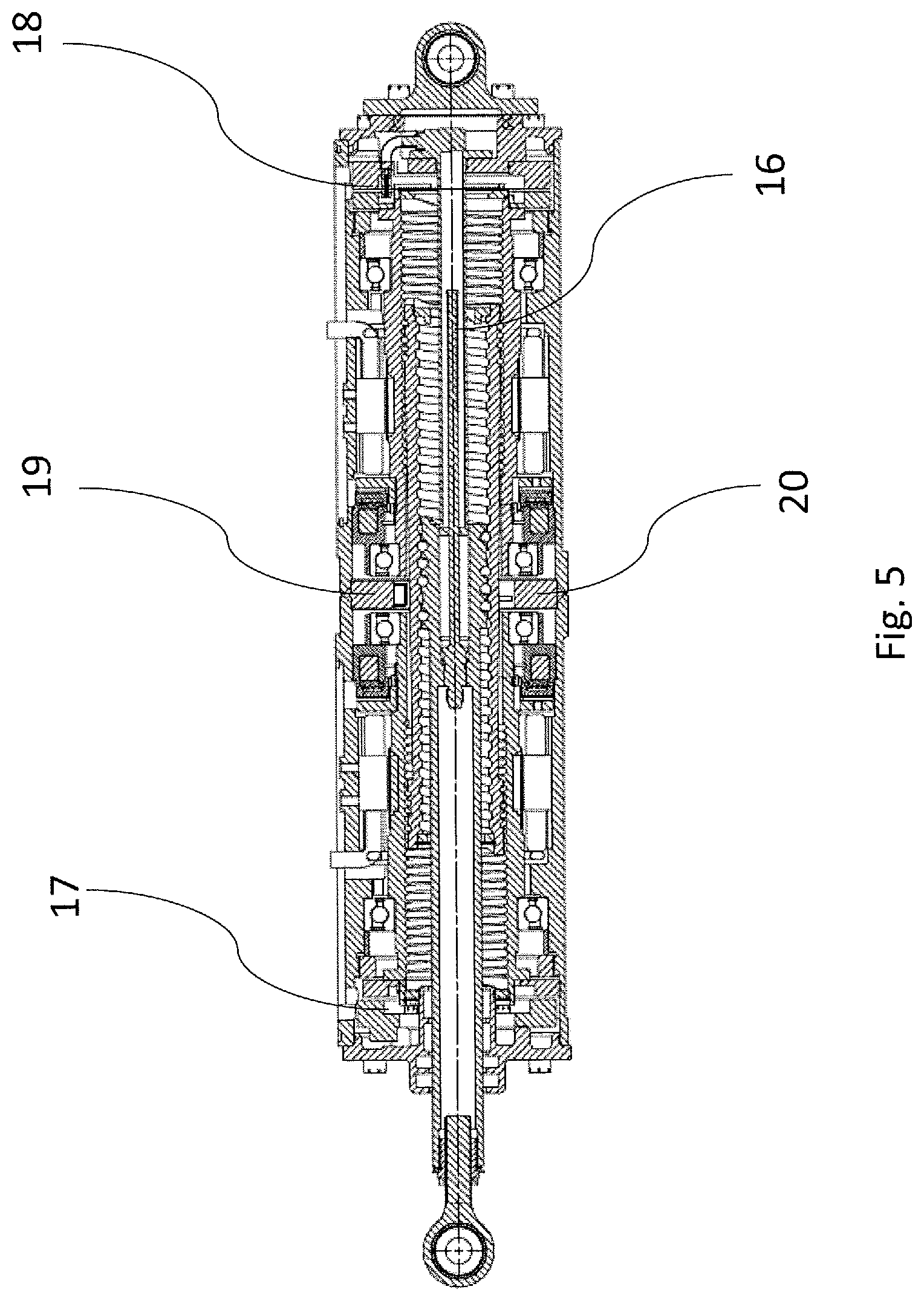
[0024] FIG. 5 shows a sectional view of the electromechanical linear actuator highlighting additional characteristic features of the actuator;
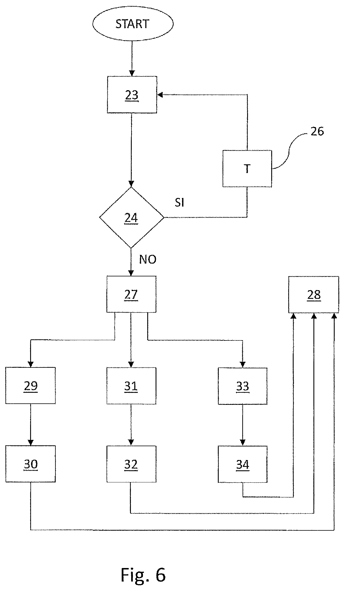
[0025] FIG. 6 shows a flow chart of the method of assessing the presence of an electrical, electronic and/or mechanical fault in an electromechanical linear actuator, according to the present invention.
DETAILED DESCRIPTION
[0026] Even when this is not expressly stated, the individual features as described with reference to the particular embodiments shall be intended as auxiliary to and/or interchangeable with other features described with reference to other exemplary embodiments.
[0027] Referring to the accompanying figures, numeral 1 generally designates an electromechanical linear actuator of the present invention and particularly FIG. 1A schematically depicts a primary control surface of an aircraft operated by the single-acting actuator 1 (i.e. having a single pushing member projecting out of one side of the actuator) and FIG. 1B schematically depicts a steering assembly of a vehicle operated by a double-acting actuator (i.e. having two pushing members projecting out of both sides of the actuator).
[0028] Referring to FIGS. 2 to 4, the actuator 1 comprises a containment structure 2 preferably rigid, and a pushing member 3.
[0029] The pushing member 3 constitutes the active element of the actuator 1.
[0030] Particularly, the pushing member 3 is designed to translate, relative to the containment structure 2, to at least partially come out of the containment structure 2 during operation of the actuator 1.
[0031] The pushing member 3 translates through a special aperture formed in the containment structure 2.
[0032] The actuator 1 comprises a mechanical reduction apparatus 4, disposed in the containment structure 2, and configured to rotate about an axis of rotation X.
[0033] The actuator 1 comprises motor means 5, disposed in the containment structure 2, which are operatively connected with the mechanical reduction apparatus 4 to rotate it about the axis X.
[0034] The actuator 1 comprises a shaft 6, which fits into the mechanical reduction apparatus 4, and is connected with the pushing member 3.
[0035] Particularly, the shaft 6 comprises a first terminal end 6' and a second terminal end 6'', where the first terminal end 6' is connected to a coupling eye 3'. The second terminal end 6'' may come out of the containment structure 2 with the pushing member 3 at least partially during operation of the actuator 1.
[0036] The actuator 1 comprises a rotation-preventing mechanism 7 which is operable on the shaft 6 to prevent the shaft from rotating about the axis of rotation X.
[0037] Therefore, the shaft 6 is connected with the mechanical reduction apparatus 4 in such a manner that a rotation of the mechanical reduction apparatus 4 will cause a translation of the shaft 6 along the axis of rotation X and hence a linear reciprocating motion of the pushing member 3.
[0038] Advantageously, the mechanical reduction apparatus 4 comprises a first lead nut 8 and a second lead nut 9 which are independent of each other, i.e. two separate and distinct lead nuts.
[0039] Each lead nut 8, 9 has its own thread and its own thread direction, and is adapted to rotate about the axis of rotation X under the action of the motor means 5.
[0040] Each lead nut 8, 9 has a main direction of extension which coincides with the aforementioned axis of rotation X.
[0041] Each lead nut 8, 9 is enabled to only rotate about the axis of rotation X while to each of them the translation along the axis of rotation X is prevented, for example by means of appropriate stopping shoulders or other solutions known to the skilled person and not described herein.
[0042] In order to allow each lead nut 8 and 9 to rotate about the axis of rotation X, the actuator 1 comprises a pair of bearings 13-14 and 13'-14' for each lead nut, disposed in the containment structure 2.
[0043] For example, the pair of bearings 13-14 are designed for the lead nut 8 and 13'-14' are designed for the lead nut 9.
[0044] Thus, the lead nuts 8 and 9 are able to rotate about the axis of rotation X under the action of the motor means 5, which are connected to the lead nut or by means of a kinematic chain (e.g. a gear box comprising differential gearing), or are preferably directly connected to such lead nuts as better explained hereafter.
[0045] In one aspect, the mechanical reduction apparatus 4 comprises coupling means 10, 11 and 15, which are configured to mechanically couple the first and second lead nuts 8, 9 with the shaft 6, so that a rotational movement of the first and/or second lead nuts 8, 9 will cause a translation of the shaft 6 along the axis of rotation X.
[0046] In other words, the actuator 1 is able to ensure a translation of the shaft 6 along the axis of rotation X even in failure conditions of the motor means 5, or their respective electronics, or in case of jamming of the coupling means 10, 11 and 15 with one of the two either of the lead nuts 8, 9 indistinctly.
[0047] This is achieved without using differential systems, such as gear boxes.
[0048] For this purpose, the coupling means 10, 11 and 15 comprise: [0049] an intermediate coupling stage 10 inserted inside the first and second lead nuts 8, 9. [0050] respective first mechanical connection means 15 configured to mechanically couple each lead nut 8 and 9 with the intermediate coupling stage 10; [0051] second mechanical connection means 11.
[0052] Particularly, the shaft 6 is fitted into the intermediate coupling stage 10 and is connected with the latter via the second mechanical connection means 11.
[0053] In one aspect, the intermediate coupling stage 10, extends about an axis that coincides with the aforementioned axis of rotation X.
[0054] The intermediate coupling stage 10 has an inner cavity, preferably a through cavity, which extends along an axis that coincides with the aforementioned axis of rotation X, and which imparts a tubular shape to such intermediate coupling stage 10.
[0055] Therefore, also referring to FIGS. 2 to 4, the shaft 6 is coaxial with both the intermediate coupling stage 10 and the first and second lead nuts 8 and 9 along the axis of rotation X, so as the intermediate coupling stage 10 is coaxial with the first and second lead nuts 8 and 9 still along the axis of rotation X.
[0056] In one aspect, still referring to FIGS. 2 to 4, it shall be noted that the first mechanical connection means 15 preferably comprise a nut and screw coupling or, alternatively, a satellite roller or recirculating roller coupling or a recirculating ball screw.
[0057] Referring now to FIGS. 2 and 3, which shows a preferred embodiment of the coupling between the intermediate stage 10 and the shaft 6, it shall be noted that the shaft 6 is a screw shaft and the second mechanical connection means 11 comprise a nut and screw coupling between the screw shaft 6 and the intermediate coupling stage 10.
[0058] With this embodiment, a rotary motion imparted by the motor means 5 to the first and/or second lead nuts 8, 9, will cause a rotational, translational or rototranslational movement of the intermediate coupling stage 10 along the axis of rotation X, and the intermediate coupling stage 10 will in turn cause a translational movement of the screw shaft 6 along said axis of rotation X.
[0059] Therefore, in the preferred embodiment, the intermediate coupling stage 10 is interconnected with each lead nut 8 and 9 via a respective nut and screw coupling obtained with the respective first mechanical connection means 11 and after a rotation of the first lead nut 8 and/or the second lead nut 9 imparted by motor means 5, will cause a rotational, translational or rototanslational movement of the intermediate coupling stage 10 along the axis of rotation X, and that the latter, i.e. the intermediate coupling stage 10, will cause a translational displacement of the screw shaft 6 along said axis of rotation X.
[0060] For this purpose, in the preferred embodiment, the intermediate coupling stage 10 has externally a first external thread 10A and a second external thread 10B i.e. formed on its outer surface, each being designed to be coupled with a respective thread of a lead nut 8 or 9.
[0061] For example, the first thread 10A is coupled with the thread of the lead nut 8 and the second thread 10B is coupled with the thread of the lead nut 9.
[0062] In one aspect, it is expected that the first thread 10A is located proximate to a first terminal end 10' of the intermediate coupling stage 10 and said second thread 10B is located proximate to a second terminal end 10'' opposite to the first terminal end 10' of the intermediate coupling stage 10.
[0063] These first and second threads 10A and 10B preferably cover only a portion of the outer surface of the intermediate coupling stage 10, and particularly a portion that starts from the respective terminal ends 10', 10'' and extends toward the central zone of the intermediate coupling stage 10.
[0064] Since the first lead nut 8 and the second lead nut 9 are independent of each other but are still mechanically connected by the engagement of the screw lead nut with the intermediate coupling stage 10, then also the first and second threads 10A and 10B of the intermediate coupling stage 10 are fastened together, as they are formed on the same outer surface of the intermediate element 10.
[0065] In one aspect, still in the preferred embodiment of the actuator 1 as shown in FIGS. 2 and 3, it is expected that the intermediate coupling stage 10 has internally to have a third internal thread 10C, i.e. formed on its inner surface, which is designed to be coupled with a thread 6A of the screw shaft 6, such thread 6A being formed on the outer surface of the screw shaft.
[0066] In other words, the screw shaft 6 has the thread 6A with a given pitch and a given direction, which is interconnected with the third thread 10C formed in the intermediate coupling stage 10, such that a nut and screw coupling is created thereby.
[0067] In one aspect, the pitch of the thread 6A of the screw shaft 6 is different from, for instance greater or smaller than, the pitch of the thread of the first and second lead nuts 8 and 9.
[0068] Particularly: [0069] the thread direction of the first lead nut 8 is left-handed, whereas the one of the second lead nut 9 is right-handed, or vice versa (i.e. the thread direction of the first lead nut 8 is right-handed and the one of the second lead nut 9 is left-handed).
[0070] Referring now to FIG. 4, which shows a possible embodiment of the coupling between the intermediate stage 10 and the shaft 6 (which is not a screw shaft as shown in FIG. 2), it shall be noted that the second mechanical connection means 11 are embodied by bearings. If the coupling between the intermediate stage 10 and the shaft 6 is provided by bearings, then the shaft 6 will only translate in response to a translation or rototranslation of the intermediate stage 10.
[0071] If the intermediate stage 10 rotates, then the shaft 6 cannot translate. In this case, the actuator 1 still ensures electrical and electronic redundancy, but loses its mechanical redundancy (jamming). For example, if jamming occurs between a lead nut 8 or 9 and the intermediate stage 10, then the intermediate stage 10 will not be able to translate and then it can not drive the shaft 6.
[0072] In other words, in the arrangement of FIG. 4, i.e. with the presence of bearings between the intermediate stage and the shaft, the method of the present disclosure can assess whether a latent failure exists in the electrical and electronic part, but cannot assess whether such a failure exists in the mechanical part, as the latter has no redundancy.
[0073] Alternatively, the second mechanical connection means 11 can be embodied by a satellite rollers or recirculating roller coupling or a recirculating ball screw.
[0074] As discussed above, the lead nuts 8 and 9 are able to rotate about the axis of rotation X under the action of the motor means 5, which are preferably directly connected to such lead nuts.
[0075] For this purpose, regardless of the embodiment as shown in FIG. 2 and 3 or 4, the motor means 5 comprise two electric motors 5A and 5B, each being directly operable on a respective lead nut 8 or 9.
[0076] Particularly, each electric motor 5A, 5B comprises a stator fixed to the containment structure 2 and a rotor fixed to its respective lead nut 8, 9.
[0077] Therefore, the rotor of each electric motor 5A and 5B is rigidly connected with a respective lead nut 8 or 9, one or both of the latter being rotated by the electromagnetic interaction of their respective rotors (generally with permanent magnets) and the stators.
[0078] For example, also referring to FIG. 3, it shall be noted that the rotor of the electric motor 5A is fixed to the first lead nut 8, whereas the rotor of the motor 5B is fixed to the second lead nut 9.
[0079] In an alternative embodiment, the motor means 5 are designed to be connected with a respective lead nut 8 or 9 via a kinematic chain (not shown) to distribute the torque to one and/or both of said first and second lead nuts 8 and 9.
[0080] The actuator 1 comprises braking means 12, operable on the first and/or second lead nuts 8, 9 to brake the rotation about the axis of rotation X of one and/or both of said first and second lead nuts, according to the operating conditions of the actuator 1 as described in greater detail hereinafter.
[0081] Particularly, the braking means 12 comprise two electric brakes 12A and 12B, each operable on a respective lead nut 8 or 9.
[0082] Here, the brakes are, for example, electromagnetic coil brakes. Namely, they are of the normally open configuration (with the brake being closed by actuating the electromagnet), or of the normally closed configuration (with the brake being opened by actuating the electromagnet).
[0083] For example, also referring to FIG. 3, it shall be noted that the brake 12A operates on the first lead nut 8, and the brake 12B operates on the second lead nut 9.
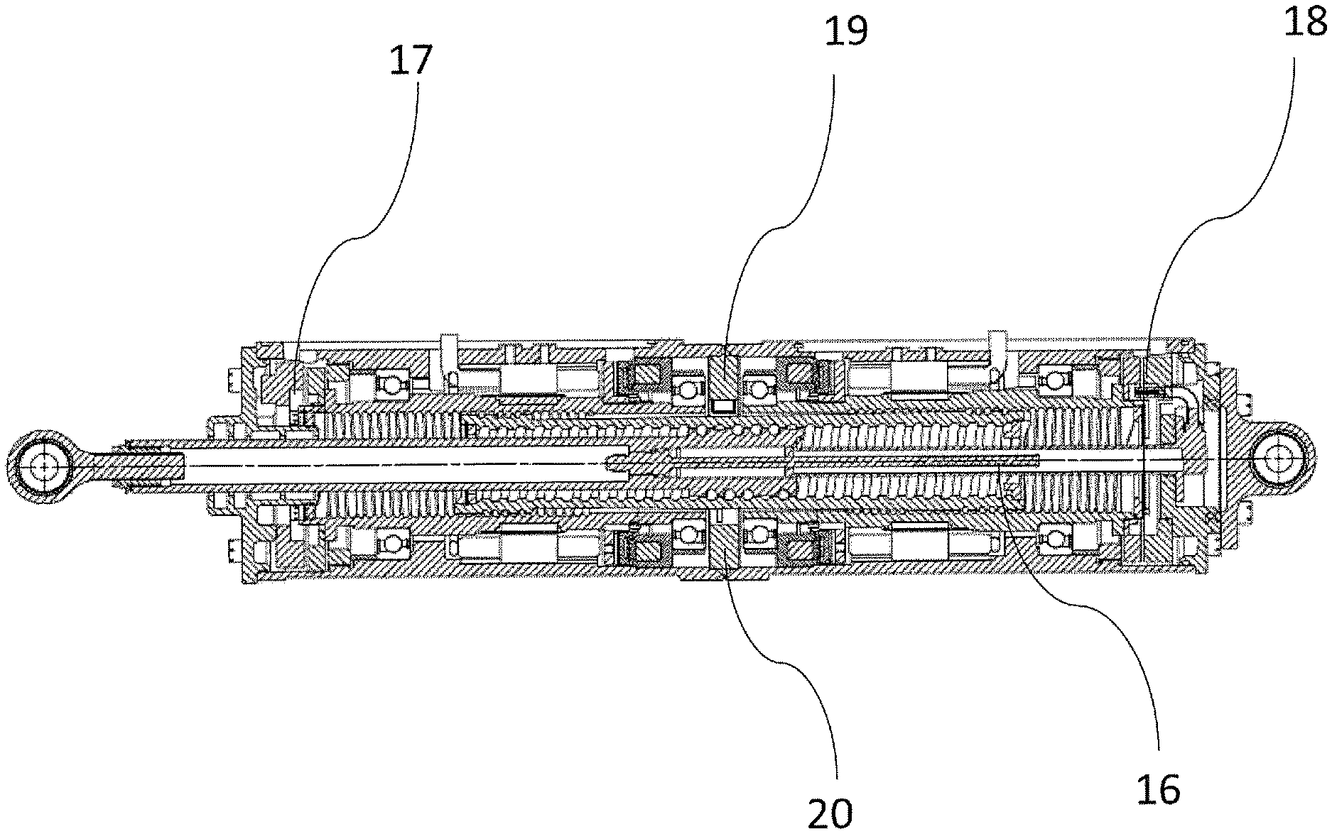
[0084] It shall be noted that each electric motor 5A and 5B as well as each electric brake 12A and 12B is controlled by its own control electronics (not shown), which is designed to check and command the operating state and effectiveness of the aforementioned electric motors 5A and 5B and electric brakes 12A and 12B. The actuator comprises a plurality of sensors 16-20, arranged within the containment structure 2 and suitably configured to be in signal communication with the command and control electronics, and designed to detect the position of the shaft 6, to thereby detect its movements along the axis X.
[0085] Particularly, the actuator 1 comprises three types of sensors: [0086] at least one linear sensor 16, which is placed inside of the screw shaft 6 and is configured to detect the axial position of the shaft 6; [0087] first 17 and second 18 rotary sensors, each associated with a respective lead nut 8, 9 and each configured to detect the rotation of each lead nut 8, 9; [0088] at least one proximity sensor 19, 20 located between the two lead nuts 8, 9 and configured to read the axial position of the intermediate coupling stage 10.
[0089] These sensors 16, 17, 18, 19, 20 are connected via the command/control electronics and appropriate software to monitor the relative movements between the screw shaft 6, the lead nuts 8, 9, the intermediate coupling stage 10 and the containment structure 2.
[0090] More in detail, the proximity sensor 19, 20 and the linear sensor 16 can ensure homing of the rotary sensors 17, 18 located proximate to each lead nut 8, 9. Advantageously, the proximity sensor 19, 20 and the linear sensor 16 identify a reference point for the first 17 and second 18 rotary sensors to obtain the position of the two lead nuts 8, 9.
[0091] Advantageously, the presence of multiple sensors 16, 17, 18, 19, 20 ensures redundancy for measuring the axial position of the screw shaft 6.
[0092] It shall be noted that two sensors of the plurality 16, 17, 18, 19, 20 might be sufficient to obtained the axial position of the screw shaft 6, by mechanical correlations.
[0093] Nevertheless, using the plurality of sensors 16-20 as described above, the actuator 1 will be able to tolerate the failure of up to two sensors.
[0094] Advantageously, the control/command electronics correlates the outputs of the sensors 16, 17, 18, 19, 20 to identify a mechanical failure (i e jamming) between the screw shaft 6 and the intermediate coupling stage 10 or between the lead nuts 8, 9 and the intermediate coupling stage 10.
[0095] Therefore, in the preferred embodiment as described herein (i.e. the one as shown in FIG. 2 or 3), the actuator 1 comprises two independent electric motors 5A and 5B and two independent electronics for driving fully redundant mechanics (i.e. two lead nuts 8 and 9, an intermediate stage 10 and a screw shaft 6) without using gear boxes and comprises the use of two independent lead nuts 8 and 9, one with a right-handed thread direction and the other with a left-handed thread direction, with which the rotors of the two electric motors 5A and 5B are directly connected. The two lead nuts 8 and 9 engage the intermediate stage 10 which has two distinct external threaded portions 10A and 10B, one engaged with the left-handed lead nut and the other engaging the right-handed lead nut. Therefore, the intermediate stage 10 has a thread 10C that engages the thread 6A of the screw shaft 6 which does not rotate thanks to the rotation-preventing device 7.
[0096] It should be further noted, still in the preferred embodiment as described herein, that the right-handed and left-handed coupling between the intermediate stage 10 and the respective lead nuts 8 and 9, can indicate the position of the intermediate stage 10 with respect to the lead nuts and the screw shaft 6. This will define a much smaller positioning range in which jamming may occur between the intermediate stage 10 and the lead nuts 8 and/or 9 or between the intermediate stage 10 and the screw shaft 6 as compared with prior art actuators. Thus, a much more compact actuator will be advantageously obtained, which has a lighter weight while ensuring that the actuator 1 will cover its entire stroke even under a jamming condition.
[0097] The method of assessing the presence of any problem or fault, particularly latent failures, in an electromechanical actuator 1 will be now described, also with reference to FIG. 6, with reference to its preferred embodiment, i.e. the embodiment as shown in FIG. 2 or 3.
[0098] Fault Assessment Mode
[0099] During normal operation, the two electric motors 5A and 5B may drive the two lead nuts 8 and 9, upon request by respective electronics, in the same direction of rotation or in opposite directions of rotation.
[0100] If the operation of the two motors 5A and 5B moves the two lead nuts 8 and 9 in the same direction of rotation, then the intermediate stage 10 rotates in rigidly joined fashion with the two lead nuts 8 and 9. Due to the rotation-preventing device 7, the screw shaft 6 translates.
[0101] If the operation of the two motors 5A and 5B moves the two lead nuts 8 and 9 in opposite directions, then the torque of one motor is counterbalanced by the torque of the other motor and the intermediate stage 10 translates. The screw shaft 6 translates in rigidly joined fashion with the intermediate stage 10.
[0102] As a result, in the fault assessment mode, the intermediate stage 10 may rotate, translate or roto-translate and the screw shaft 6, due to the presence of the rotation-preventing device 7, translates along the axis of rotation X to thereby provide a linear reciprocating motion, still along the axis of rotation X of the pushing member 3.
[0103] In one aspect, the presence of electric, electronic, and/or mechanical faults, particularly latent failures in the electromechanical linear actuator 1 may be assessed through the following steps: [0104] actuating the two electric motors 5A, 5A, block 23, to drive the first and second lead nuts 8, 9 in the same direction of rotation or in opposite directions of rotation; [0105] during said step of actuating the two electric motors 5A, 5B, checking, block 24, whether the shaft 6 translates relative to said containment structure 2.
[0106] Particularly, due to the command and control electronics and due to the plurality of sensors 16-20 it is possible identify whether the shaft 6 actually translates relative to the containment structure 2.
[0107] In one aspect, if no fault is detected, branch YES of block 24, then the step of actuating the two electric motors 5A, 5B will be carried out with a predetermined actuating range T, block 26.
[0108] For example, the actuating range of T may have a constant or variable repetition frequency.
[0109] If the shaft 6 does not translate relative to the containment structure 2, branch NO of block 24, then it is planned to intervene according to one of the modes designed do ensuring correct operation of the actuator 1, block 27 step of determining the type of fault, and the step of notifying the type of failure that has been detected, block 28.
[0110] Particularly, if the command and control electronics does not detect a translation of the shaft 6, then the monitoring electronics will enter a so-called failure mode.
[0111] For this purpose, the command and control electronics will identify, using the sensors 16-20, which electric or electronic component (for example one of the two electric motors or the electronics itself) or mechanical component (e.g. jamming of the intermediate stage of the screw with either of the lead nuts or jamming of the screw shaft with the intermediate stage of the screw) is faulty.
[0112] The modes for locating and repairing a fault in an electrical or electronic part or a mechanical part of the actuator 1 will be described below.
[0113] In these scenarios, the method always includes notification of the detected fault, block 28.
[0114] Operating mode in case of failure (indistinctly failure of one of either electric motor or respective electronics)
[0115] The method determines which type of fault has occurred and, in case of indistinctly failure in either of the two electric motors 5A or 5B or their respective electronics, block 29, then a step of actuating the electric brake 12A or 12B is actuated to stop the rotation of the lead nut 8 or 9 on the side of the faulty motor/electronics is provided, block 30.
[0116] For example, the brake 12A stops the rotation of the lead nut 8 if the failure occurs in the motor 5A and/or its the command and control electronics.
[0117] This will involve the rototranslation of the intermediate stage 10 along the axis of rotation X due to the rotation of the lead nut 9 driven by the electric motor 5B. Due to the rotation-preventing device 7, the screw shaft 6 translates along the axis of rotation X as a result of the translation and rotation of the intermediate layer 10 as the latter is coupled by its thread 10C with the thread 6A of the screw shaft 6.
[0118] The translation of the screw shaft 6 provides the linear reciprocating motion, still along the axis of rotation X of the pushing member 3.
[0119] Operating mode in case of failure (jamming of the intermediate stage of the screw with either of the lead nuts)
[0120] The method determines which type of fault occurred and if the failure is a mechanical failure (or jamming) of the intermediate stage 10 with either of the lead nuts 8 or 9, block 31, e g jamming of the intermediate stage 10 with the lead nut 8, then a step of actuating the two electric motors 5A and 5B by their respective electronics in the same direction of rotation is provided, block 32.
[0121] In this scenario, the intermediate stage 10 rotates about the axis of rotation X in rigidly joined fashion with the two lead nuts 8 and 9. Due to the presence of the rotation-preventing device 7, the screw shaft 6 translates along the axis of rotation X to thereby provide a linear reciprocating motion, still along the axis of rotation X of the pushing member 3.
[0122] Operating mode in case of failure (jamming of the screw shaft with the intermediate stage of the screw)
[0123] The method determines which type of fault occurred and if the failure is a failure (or jamming) of the screw shaft 6 with the intermediate stage 10, block 33, then a step of actuating the two electric motors 5A and 5B by their respective electronics in opposite directions of rotation is provided in which, block 34.
[0124] In this scenario, the torque of one motor is counterbalanced by the torque of the other motor and the intermediate stage 10 only moves along the axis of rotation X. The screw shaft 6 translates along the axis of rotation X in rigidly joined fashion with the intermediate stage 10, to thereby provide a linear reciprocating motion, still along the axis of rotation X of the pushing member 3.
[0125] Those skilled in the art will obviously appreciate that a number of changes and variants as described above may be made to fulfill particular requirements, without departure from the scope of the invention, as defined in the following claims.
* * * * *
D00000
D00001
D00002
D00003
D00004
D00005
D00006
XML
uspto.report is an independent third-party trademark research tool that is not affiliated, endorsed, or sponsored by the United States Patent and Trademark Office (USPTO) or any other governmental organization. The information provided by uspto.report is based on publicly available data at the time of writing and is intended for informational purposes only.
While we strive to provide accurate and up-to-date information, we do not guarantee the accuracy, completeness, reliability, or suitability of the information displayed on this site. The use of this site is at your own risk. Any reliance you place on such information is therefore strictly at your own risk.
All official trademark data, including owner information, should be verified by visiting the official USPTO website at www.uspto.gov. This site is not intended to replace professional legal advice and should not be used as a substitute for consulting with a legal professional who is knowledgeable about trademark law.