Outdoor Floor Box Enclosure
Bonilla; Nelson ; et al.
U.S. patent application number 16/792801 was filed with the patent office on 2020-06-11 for outdoor floor box enclosure. The applicant listed for this patent is Hubbell Incorporated. Invention is credited to Nelson Bonilla, David L. Lutz.
| Application Number | 20200185897 16/792801 |
| Document ID | / |
| Family ID | 57943785 |
| Filed Date | 2020-06-11 |


| United States Patent Application | 20200185897 |
| Kind Code | A1 |
| Bonilla; Nelson ; et al. | June 11, 2020 |
OUTDOOR FLOOR BOX ENCLOSURE
Abstract
An outdoor enclosure provides weather protection for electrical equipment. More particularly, an outdoor enclosure having a cover flush with the floor or the ground and an interior space beneath the floor or ground is provided. The interior space is maintained in a water-tight condition when the cover of the enclosure and a door within the cover are closed and a drain is provided in the floor of the interior space to allow water to drain from the interior space if and when such water enters the enclosure. Electrical cables and a receptacle with ground fault protection are stowed within the enclosure and pulled through the door in the cover when a user needs access to electrical power via the receptacle.
| Inventors: | Bonilla; Nelson; (Winter Garden, FL) ; Lutz; David L.; (Woodbridge, CT) | ||||||||||
| Applicant: |
|
||||||||||
|---|---|---|---|---|---|---|---|---|---|---|---|
| Family ID: | 57943785 | ||||||||||
| Appl. No.: | 16/792801 | ||||||||||
| Filed: | February 17, 2020 |
Related U.S. Patent Documents
| Application Number | Filing Date | Patent Number | ||
|---|---|---|---|---|
| 15231158 | Aug 8, 2016 | 10566776 | ||
| 16792801 | ||||
| 62201927 | Aug 6, 2015 | |||
| Current U.S. Class: | 1/1 |
| Current CPC Class: | H02G 9/10 20130101; H02G 11/00 20130101; H02G 3/088 20130101; H02G 3/185 20130101 |
| International Class: | H02G 3/08 20060101 H02G003/08; H02G 9/10 20060101 H02G009/10; H02G 3/18 20060101 H02G003/18 |
Claims
1. An outdoor enclosure for holding electrical equipment beneath the surface of a floor or ground, the outdoor enclosure comprising: a housing enclosing a recessed interior space; a cover movable between a closed position in which the cover is positioned adjacent an upper end of the interior space, and an open position in which the upper end is exposed to permit access to the interior space; a utility electrical cable disposed within the interior space, the cable including a first end and a second end, the first end configured to receive electrical current from a power source; and an electrical device in electrical communication with the second end of the cable, the electrical device selectively stored in the interior space, the electrical device removable from the interior space of the housing while electrically connected to the second end of the cable.
2. The outdoor enclosure of claim 1, wherein the cover includes an opening through which the cable can pass while the electrical device is positioned outside of the interior space and the cover is in the closed position.
3. The outdoor enclosure of claim 2, wherein the cover further includes a secondary cover for selectively closing the opening of the cover.
4. The outdoor enclosure of claim 3, wherein the secondary cover is a door pivotably coupled to the cover.
5. The outdoor enclosure of claim 2, wherein the second end of the utility electrical cable and the electrical device can be pulled through the opening of the cover while the cover is in a closed position and the secondary cover is open.
6. The outdoor enclosure of claim 1 wherein the electrical device includes a duplex receptacle and a ground fault module that protects the duplex receptacle.
7. The outdoor enclosure of claim 1, wherein the electrical device is a watertight device.
8. The outdoor enclosure of claim 1, wherein the housing includes a flange positioned adjacent an upper end of the interior space, the cover supported on the flange.
9. The outdoor enclosure of claim 8, wherein an upper surface of the cover is flush with an upper surface of the flange when the cover is in the closed position, the flange extending along at least a portion of a perimeter of the housing.
10. The outdoor enclosure of claim 1, wherein the housing includes a drain hole positioned adjacent a lower end of the housing.
11. The outdoor enclosure of claim 1, further comprising: a junction box attached to a wall of the housing; and a conduit attached to the junction box and carrying mains electrical cables, the mains electrical cables being electrically connected to the first end of the cable in the junction box.
12. An outdoor enclosure for holding electrical equipment beneath the surface of a floor or ground, the outdoor enclosure comprising: a housing enclosing a recessed interior space; a cover positioned adjacent an upper end of the housing, the cover movable between an open position and a closed position, the cover operable to expose the interior space in the open position and enclose the interior space in the closed position, the cover including an opening; a utility electrical cable disposed within the interior space, the cable including a first end and a second end, the first end configured to receive electrical current from a power source; an electrical device in electrical communication with the second end of the cable, the electrical device selectively stored in the interior space, the electrical device removable from the interior space of the housing while electrically connected to the second end of the cable, the cable being capable of passing through the opening of the cover while the electrical device is positioned outside of the interior space and the cover is in the closed position.
13. The outdoor enclosure of claim 12, wherein the cover further includes a secondary cover for selectively closing the opening of the cover.
14. The outdoor enclosure of claim 13, wherein the secondary cover is a door pivotably coupled to the cover.
15. The outdoor enclosure of claim 12, wherein the cable and the electrical device can be stowed within the interior space, wherein the second end of the utility electrical cable and the electrical device can be pulled through the opening of the cover while the cover is in a closed position and the secondary cover is open, the electrical device being electrically connected to the cable while positioned exterior to the housing.
16. The outdoor enclosure of claim 12, wherein the electrical device includes a duplex receptacle and a ground fault module that protects the duplex receptacle.
17. The outdoor enclosure of claim 12, wherein the housing includes a flange positioned adjacent an upper end of the interior space, the cover supported on the flange.
18. The outdoor enclosure of claim 18, wherein an upper surface of the cover is flush with an upper surface of the flange when the cover is in the closed position, the flange extending along at least a portion of a perimeter of the housing.
19. The outdoor enclosure of claim 12, wherein the housing includes a drain hole positioned adjacent a lower end of the housing.
20. The outdoor enclosure of claim 12, further comprising: a junction box attached to a wall of the housing; and a conduit attached to the junction box and carrying mains electrical cables, the mains electrical cables being electrically connected to the first end of the cable in the junction box.
Description
RELATED APPLICATIONS
[0001] The present application is a continuation of co-pending, prior-filed U.S. patent application Ser. No. 15/231,158, filed Aug. 8, 2016, which claims priority to U.S. Provisional Application No. 62/201,927, filed Aug. 6, 2015, the entire contents of which are hereby incorporated.
FIELD
[0002] This invention relates to electrical enclosures, in particular to electrical floor box enclosures intended for use outdoors or in other locations where wet conditions exist or are expected.
BACKGROUND
[0003] Floor box enclosures for housing electrical devices such as power receptacles typically have a hinged cover that can be opened for access to the enclosure interior. The enclosure is installed with the cover substantially at ground or floor level. Keeping the housed devices dry, or at least out of direct contact with water, presents a challenge when rain or surface water is present, and especially when a cable connected to a device extends out of the enclosure.
SUMMARY
[0004] An enclosure consistent with embodiments of the invention disclosed herein has a cover with a cable door, a water-tight junction box and an opening in its bottom that allows water to drain from the enclosure. At least one marine-grade, water-tight cable set is hard-wired to the line in the junction box and can be stowed in the enclosure. The cable set can be pulled out of the enclosure when needed, such as for powering lighting or other equipment for events or other functions.
[0005] According to one exemplary embodiment an outdoor enclosure for holding electrical equipment beneath the surface of a floor or the ground is provided having a housing with an interior space defined by four walls and a floor disposed at the base of the four walls, a flange surrounding a perimeter of the housing at substantially a right angle to a top of the four walls, a cover disposed within an interior perimeter of the flange at the top of the four walls, the cover being operable to expose said interior space of said housing in an open position and enclose the interior space of said housing in a closed position. The outdoor enclosure according to this exemplary embodiment further includes one or more utility electrical cables disposed within the interior space, the cables having a first end protruding through one or more of the four walls or the floor of the housing and a second end electrically connected to an electrical device.
[0006] According to a further exemplary embodiment an outdoor enclosure for holding electrical equipment beneath the surface of a floor or the ground is provided having a rectangular housing with an interior space defined by four walls and a floor having a drain hole disposed at the base of the four walls. A flange surrounding a perimeter of the housing at a top of the four walls and a cover flush with the flange and disposed within an interior perimeter of the flange at the top of the four walls is also provided. The cover is operable to expose the interior space of the housing in an open position and enclose the interior space of the housing in a closed position. According to this exemplary embodiment a water-tight junction box and one or more utility electrical cables are disposed within the interior space. The utility electrical cables have a first end disposed within the junction box and a second end electrically connected to an electrical device.
BRIEF DESCRIPTION OF THE DRAWINGS
[0007] Exemplary embodiments of the disclosed invention are described in detail below, purely by way of example, with reference to the accompanying figures, in which:
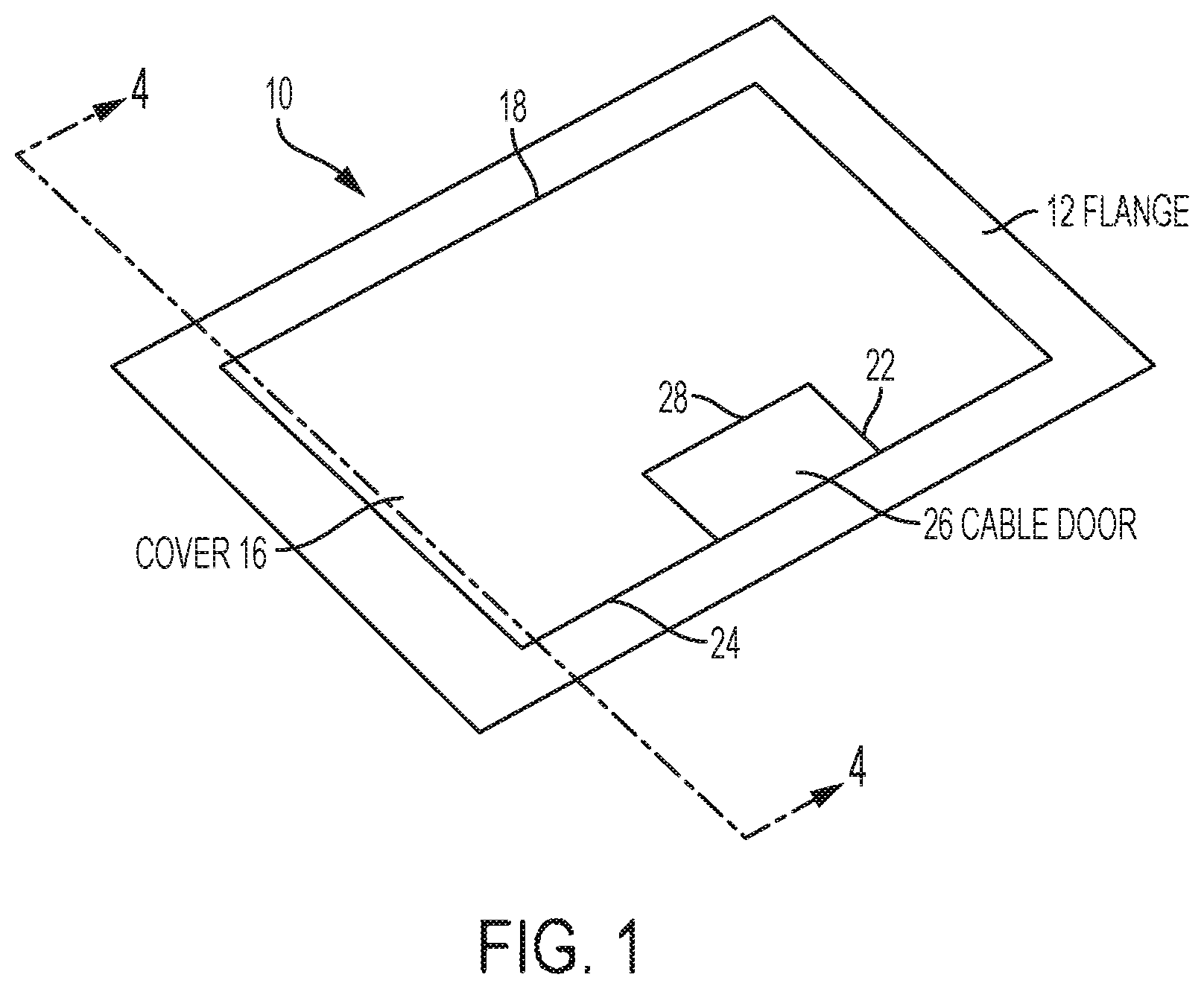
[0008] FIG. 1 is a top perspective view of a first embodiment of the enclosure of the invention, shown installed in the ground with the cover closed;
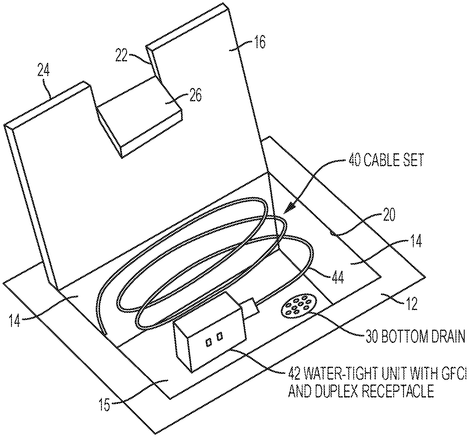
[0009] FIG. 2 is a top perspective view thereof shown with the cover open and the cable set stowed therein;
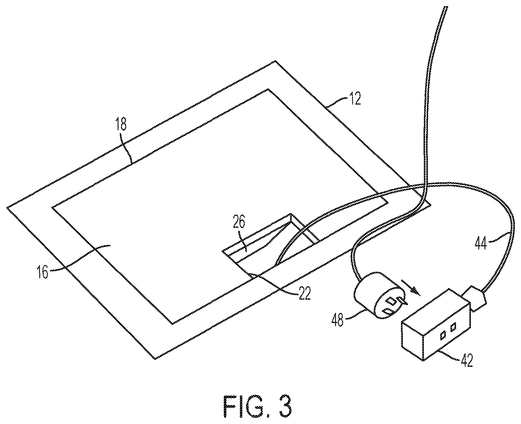
[0010] FIG. 3 is a top perspective view thereof shown with the cover closed and the cable set extending outward through the cable door opening;
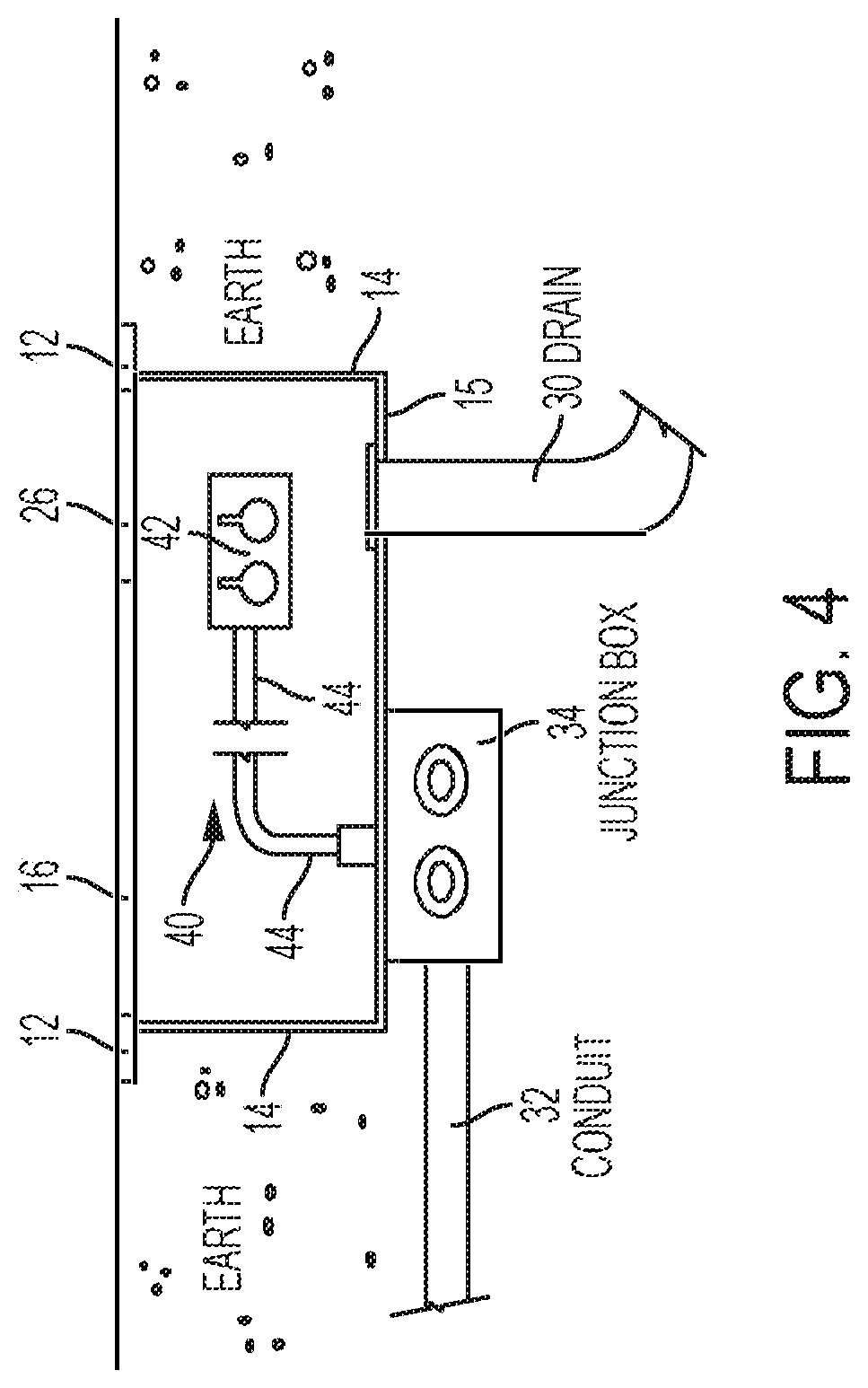
[0011] FIG. 4 is a cross-sectional view thereof taken along line 4-4 in FIG. 1;
[0012] FIG. 5 is a perspective view of an exemplary device at the end of the cable set; and
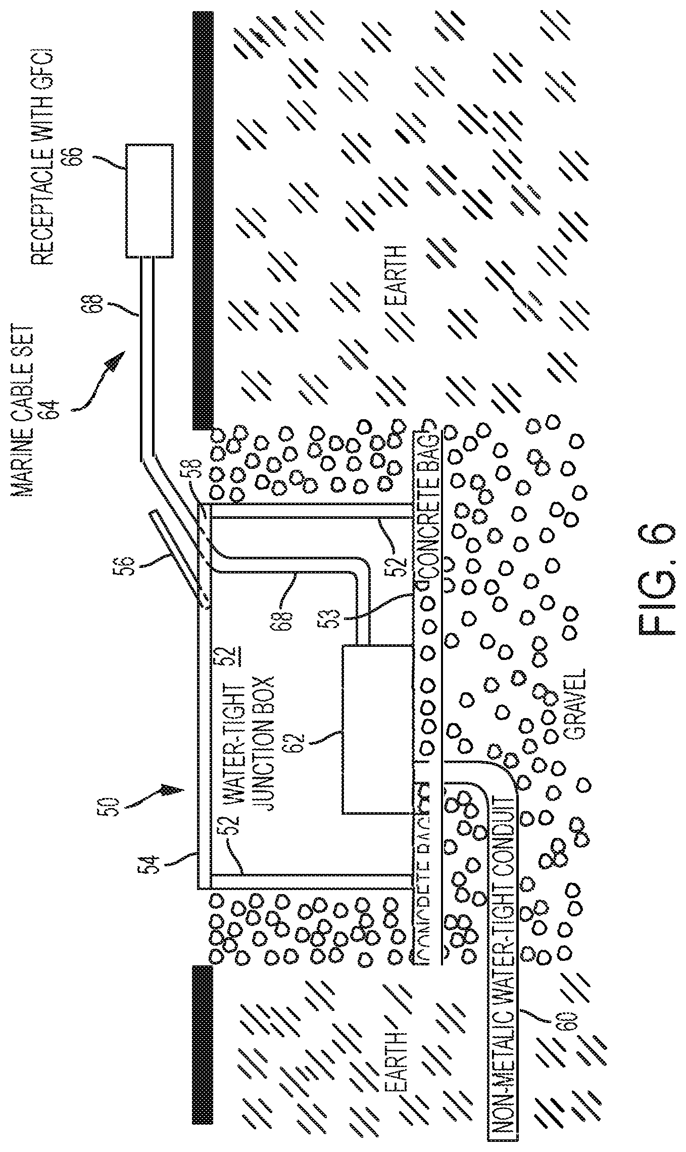
[0013] FIG. 6 is a cross-sectional view of a second embodiment of the enclosure of the invention and showing the cable set extended for use.
DETAILED DESCRIPTION OF EXEMPLARY EMBODIMENTS
[0014] Referring to FIGS. 1-4, a floor box enclosure 10 according to a first embodiment of the invention comprises four side walls 14, a bottom wall 15 joined to the side walls, and a surrounding upper flange 12 joined to the tops of the side walls. An upwardly opening cover 16 is hinged along its rear edge 18 to the flange 12 and when closed fills the opening 20 defined by the flange (see FIG. 1). When closed, cover 16 rests flush with flange 12 on one or more flange- or wall-supported stops (not shown); for example, one or more protrusions projecting from walls 14 within the enclosure. Cover 16 has a cable opening 22 at the cover's free front edge 24 and an inwardly opening cable door 26--hinged at its inner edge 28 to cover 16--which blocks cable opening 22 when closed. Cable door 26 is maintained in its closed position flush with flange 12 by a spring or a suitable latch (not shown).
[0015] Sealing gaskets (not shown) made of rubber or other suitable material are optionally provided at the interface between cover 16 and flange 12 and/or at the interface between cable door 26 and cover 16 to make the enclosure substantially water-tight when cover 16 and cable door 26 are closed. Any liquid entering the enclosure exits, for example, by the force of gravity through a drain 30 in bottom wall 15 (see FIGS. 2 and 4). In at least one embodiment floor 15 is positioned within the enclosure at an angle to facilitate water to be directed toward drain 30.
[0016] Electrical power is fed to the enclosure from beneath via, for example, a non-metallic conduit 32 joined to a water-tight junction box 34, which is mounted to the underside of bottom wall 15 (see FIG. 4). Alternatively, junction box 34 could be mounted within the enclosure and conduit 32 can be joined to walls 14 or floor 15 using a water-tight connection. A marine-grade, water-tight cable set 40 comprises a device 42 at one end of a cable 44, which is hard-wired to the line within junction box 34. Illustrated device 42 has a duplex receptacle 46 on one side protected by a ground fault module 46 on the other side (see FIG. 5) and is shown mating with a three-prong plug 48 (see FIG. 3).
[0017] When not in use, cable set 40 may be coiled up and stowed in the enclosure (see FIG. 2). When the cable set is to be used, cover 16 is raised, cable door 26 is opened and the cable set is pulled out of the enclosure. Cover 16 may then be closed, leaving cable 16 protruding through cable opening 22 (see FIG. 3). The Figures show only one cable set; however, a plurality of cable sets may be provided, all of which would be hard-wired to the line within junction box 34. In that case, the enclosure would be sized to stow all of the cable sets together.
[0018] Referring to FIG. 6, a floor box enclosure 50 according to a second embodiment of the invention has an open bottom through which liquid can drain into a gravel bed that supports and surrounds the enclosure. The enclosure comprises four side walls 52 defining a bottom opening 53, a cover 54 with a cable opening 58, and a cable door 56 hinged to the cover to open upwardly and to block the cable opening when flush with the cover. The enclosure preferably rests on concrete bags, which provide a more stable footing than the gravel bed alone. Suitable sealing gaskets (not shown) may be provided at the joints between cover 54 and side walls 52, and between cable door 56 and cover 54.
[0019] A non-metallic, water-tight conduit 60 feeds power to a water-tight junction box 62, which rests on the gravel bed within the enclosure. A marine-grade, water-tight cable set 64 comprises a device 66 at one end of a cable 68, which is hard-wired to the line within junction box 62. The illustrated device 66 is a GFCI-protected receptacle, such as that shown in FIG. 5. As in the first embodiment, a plurality of cable sets may be provided, all of which would be hard-wired to the line within junction box 62 and may be coiled up and stowed in the enclosure when not in use.
[0020] In the illustrated embodiments, the cable set terminates in a GFCI-protected duplex receptacle. This is but one example of devices that may terminate a cable set. Another example is a sleeve-type connector (socket), preferably with a water-tight flip cover, which would mate with a pin-type plug. Yet another example is a portable outlet box with either straight-blade or twist-lock devices, and protective lid covers that would power multiple end-use applications.
[0021] An alternative junction box within the enclosure could be fully sealed and waterproof and have a removable waterproof fitting that allows access to a power connector. Such a junction box could be made significantly more waterproof than standard marine or rainproof connectors. An accessory cord set could then be attached to this connector to extend power outside the enclosure to other power distribution or utilization equipment. This allows the use of standard marine or rain-proof connectors and cords for power needs, and when not in use the main connection can be made waterproof and left underground when not in use. This sealed internal box could also be on the end of a flexible waterproof cable so that it can be pulled out of the enclosure for easier access. The sealed box could be used to feed to a spider box, which would then provide power for the various end-use applications.
[0022] Additional, optional features for enclosures according to the invention could include an internal sensor linked to an external indicator to show submersion, an auto-disconnect device and/or various safety indicators.
[0023] Floor box enclosures according to the invention preferably are made of materials suitable for in-ground and likely wet conditions. A preferred material is polymer concrete, which is made from selectively graded aggregates in combination with a polymer resin system. When combined through a process of mixing, molding and curing, a powerful cross-linked bond is formed. Precast polymer concrete may be reinforced with fiberglass for enhanced strength and rigidity. Commercial examples of products made of polymer concrete are underground enclosures sold by Hubbell Power Systems, Inc. under the QUAZITE brand name.
[0024] While exemplary embodiments have been chosen to illustrate the invention, it will be understood by those skilled in the art that various changes, modifications, additions, and substitutions are possible, without departing from the scope and spirit of the invention.
* * * * *
D00000
D00001
D00002
D00003
D00004
D00005
D00006
XML
uspto.report is an independent third-party trademark research tool that is not affiliated, endorsed, or sponsored by the United States Patent and Trademark Office (USPTO) or any other governmental organization. The information provided by uspto.report is based on publicly available data at the time of writing and is intended for informational purposes only.
While we strive to provide accurate and up-to-date information, we do not guarantee the accuracy, completeness, reliability, or suitability of the information displayed on this site. The use of this site is at your own risk. Any reliance you place on such information is therefore strictly at your own risk.
All official trademark data, including owner information, should be verified by visiting the official USPTO website at www.uspto.gov. This site is not intended to replace professional legal advice and should not be used as a substitute for consulting with a legal professional who is knowledgeable about trademark law.