Scanning Immersion Microscopy
OHRT; Thomas ; et al.
U.S. patent application number 16/640710 was filed with the patent office on 2020-06-11 for scanning immersion microscopy. This patent application is currently assigned to Carl Zeiss Microscopy GmbH. The applicant listed for this patent is CARL ZEISS MICROSCOPY GMBH. Invention is credited to Michael GOEGLER, Thorsten KUES, Thomas OHRT.
| Application Number | 20200183136 16/640710 |
| Document ID | / |
| Family ID | 63244561 |
| Filed Date | 2020-06-11 |

| United States Patent Application | 20200183136 |
| Kind Code | A1 |
| OHRT; Thomas ; et al. | June 11, 2020 |
SCANNING IMMERSION MICROSCOPY
Abstract
A method for the microscopy scanning of a specimen. An immersion medium is used between a slide and a microscope objective, said immersion medium wetting a surface of the slide, and the microscope objective being relatively displaced over the surface of the slide for imaging. The surface is provided with a coating which repels the immersion medium.
| Inventors: | OHRT; Thomas; (Golmsdorf, DE) ; GOEGLER; Michael; (Wolfratshausen, DE) ; KUES; Thorsten; (Bovenden-Eddigehausen, DE) | ||||||||||
| Applicant: |
|
||||||||||
|---|---|---|---|---|---|---|---|---|---|---|---|
| Assignee: | Carl Zeiss Microscopy GmbH Jena DE |
||||||||||
| Family ID: | 63244561 | ||||||||||
| Appl. No.: | 16/640710 | ||||||||||
| Filed: | August 8, 2018 | ||||||||||
| PCT Filed: | August 8, 2018 | ||||||||||
| PCT NO: | PCT/EP2018/071472 | ||||||||||
| 371 Date: | February 20, 2020 |
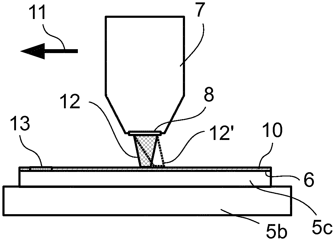
| Current U.S. Class: | 1/1 |
| Current CPC Class: | G02B 21/002 20130101; G02B 21/33 20130101; G02B 21/34 20130101 |
| International Class: | G02B 21/00 20060101 G02B021/00; G02B 21/33 20060101 G02B021/33; G02B 21/34 20060101 G02B021/34 |
Foreign Application Data
| Date | Code | Application Number |
|---|---|---|
| Aug 21, 2017 | DE | 10 2017 119 094.5 |
Claims
1. A method for examining a sample by scanning microscopy, comprising the steps of: using an immersion medium between a sample carrier or a cover slip and a microscope objective, said immersion medium wetting the sample carrier or the cover slip, displacing, for imaging purposes, the microscope objective relatively over the sample carrier or the cover slip, and using the sample carrier or cover slip, having a surface facing toward the microscope objective such that the surface repels the immersion medium.
2. The method as claimed in claim 1, wherein the surface is omniphobic.
3. The method as claimed in claim 1, further comprising the steps of initially applying the sample to a sample carrier, placing a cover slip on the sample for covering purposes, and then treating the surface of the sample carrier or cover slip, which faces the microscope objective during the examination by microscopy, to be repelling.
4. The method as claimed in claim 1, wherein the sample carrier comprises a Petri dish or a microtiter plate.
5. A sample carrier or cover slip for examining a sample, to be disposed on the sample carrier or under the cover slip, by scanning microscopy, wherein the sample carrier or the cover slip comprises one surface to be disposed toward the objective which surface is lipophobic, hydrophobic or omniphobic.
6. The sample carrier or cover slip as claimed in claim 5, comprising a marking that indicates a repelling side.
7. The sample carrier or cover slip as claimed in claim 5, comprising a sample carrier that is a Petri dish or a microtiter plate
Description
PRIORITY CLAIM
[0001] The present application is a National Phase entry of PCT Application No. PCT/EP2018/071472, filed Aug. 8, 2018, which claims priority from German Patent Application 10 2017 119 095.5, filed Aug. 21, 2017, the disclosures of which are hereby incorporated by reference herein in their entirety.
FIELD OF THE INVENTION
[0002] The invention relates to a method for examining a sample by scanning microscopy, wherein an immersion medium is used between a sample carrier and a microscope objective, said immersion medium wetting a surface of the sample carrier, and, for imaging purposes, the microscope objective is displaced in relative fashion over the surface of the sample carrier. Further, the invention relates to a sample carrier or cover slip for examining a sample, to be disposed on the sample carrier or under the cover slip, by scanning microscopy.
[0003] In microscopy, the use of immersion objectives offers many advantages, which ultimately arise from the higher obtainable numerical apertures of the objectives. An immersion medium with a refractive index that is as high as possible but does not exceed that of the cover slip of the sample maximizes the aperture in microscopy. Different immersion media are used depending on the type of sample, including organic replacement media for water, e.g., Carl Zeiss Immersol W and Immersol G. As a rule, the immersion media are liquid at the normal temperature. Water-based immersion media are used for microscopy of living cells situated in an aqueous environment. Since the refractive indices of the immersion medium and of the sample medium are very similar in that case but the cover slip, as a rule, has a different refractive index, an optical correction is needed to avoid spherical aberrations when penetrating deeper into the sample. However, this correction only applies to a certain cover slip thickness and type, which is why water immersion objectives generally have a correction mechanism that, by displacing a lens or lens group in the objective, corrects the deviations from the cover slip thickness and type that form the basis of the correction.
[0004] The prior art has disclosed various approaches for ensuring that a front lens of a microscope objective is wetted as completely as possible with an immersion medium. EP 1717628 A1 and EP 2256535 A1 disclose a mechanism for inverted microscope objectives, i.e., microscope objectives that examine a sample by microscopy from below. A mechanism is provided on the front edge of the objective casing, said mechanism preventing a drop of immersion liquid placed on the front lens from running off over the front edge of the objective casing. Moreover, provision is made of outflow tubes that drain the immersion liquid downward in targeted fashion. An inner zone of the edge is configured to repel the immersion liquid for which the microscope is designed. A surrounding outer zone is configured in exactly the opposite way, and so it drains immersion liquid reaching it to the outside. With reference to further publications, JP 4603295 discusses various concepts that avoid contamination of the objective interior with immersion liquid. Two of the solutions described therein correspond to those of the specified EP documents. A third solution, which is described in the Japanese publication, provides for a groove on the objective that prevents excess immersion liquid from running into the objective. Further, for an oil immersion-based microscope, JP 4603295 proposes a lipophilic coating on the lens surface, which is surrounded by a lipophobic coating on the edge of the lens surface. Thus, the prior art is concerned in various approaches with avoiding contamination of an objective with immersion liquid or draining excess immersion liquid in a targeted manner.
[0005] US 2015/0241682 A1, provides elastomeric immersion media. These are shape-stable but elastically deformable plastics or polymers, the glass transition point of which is situated below the temperature of use. Such elastomeric immersion media can elastically deformable under a tensile or compressive load, but subsequently return back to their original undeformed form.
SUMMARY OF THE INVENTION
[0006] Difficulties arise when using immersion media, particularly in the case of scanning microscopy. The travel speed with which the objective can be displaced over the sample is limited by the fact that shear forces occur at too high movement speeds, said shear forces possibly leading to the immersion film tearing off or to an inadmissible deformation of an elastomeric immersion medium. In the case of an elastomeric immersion medium, an excessive shear force can sometimes displace the cover slip and thus lead to the sample being destroyed. A sample holder that is not completely fixed can also be displaced in this way, rendering it impossible to approach defined coordinates in the sample again. These problems can only be counteracted by using an excessive amount of immersion medium at the beginning of the microscopy process in order to compensate for the fact that the immersion medium is lost or deformed due to the travel speed and the resulting shear forces, leading to parts of the beam path being without immersion medium. As a result, however, the sample becomes contaminated by the immersion medium and the immersion medium consumption is sometimes quite high, which is costly.
[0007] The invention is therefore based on the object of specifying a method for scanning immersion microscopy of the type specified at the outset, in which the aforementioned problem of the scanning speed and the immersion medium consumption has been solved.
[0008] The embodiments of the invention are defined in the independent and dependent claims.
[0009] In scanning immersion microscopy, the surface of the sample carrier or of the cover slip, which is provided for use with the immersion medium and over which the likewise wetted immersion objective is displaced in relative fashion, is configured in such a way that it repels the immersion medium, for example by way of a treatment to be repulsive, in particular a repulsive coating. In this way, very much lower shear forces act in the immersion medium. In the case of an immersion liquid, the surface is not smeared with immersion liquid. A drop, once applied, remains on the objective because, due to the repulsive properties, it does not adhere to, or smear on, the surface of the sample carrier or cover slip. An elastomeric immersion is distorted much less or not at all, and so, as a result, the relative speed between microscope objective and sample carrier/cover slip can be increased and, at the same time, the problem of contamination is reduced on account of the immersion-repellent coating of the surface. What was found surprisingly here is that a coating of the sample carrier/cover slip with immersion-repellent properties, which by itself appears disadvantageous at a first glance, leads to a high quality during microscopy since the immersion medium remains reliably concentrated in the gap between microscope objective and sample carrier/cover slip and in front of the front lens of the microscope objective.
[0010] To the extent that reference is made here to the surface of the sample carrier or cover slip pointing toward the microscope objective, this is tantamount to the surface to be wetted with the immersion medium. In the method with a cover slip, the surface of the cover slip pointing away from the sample carrier is wetted with the immersion medium. In respect of the sample carrier or cover slip, the surface provided for wetting with the immersion medium is provided with a lipophobic, hydrophobic or omniphobic configuration.
[0011] The term surface treatment stipulates that this obtains the desired repulsive properties. The treatment can be a coating. This is preferred and will be described below purely by way of example. Equally, however, a structure could also be introduced into the surface, said structure producing the repulsive properties, or the surface could be treated in some other way, for example chemically, in order to obtain the repulsive properties.
[0012] For microscopy, a sample carrier or cover slip is provided, the surface of which, which is subsequently wetted with immersion medium, has been treated accordingly. The terms "sample carrier" and "cover slip" should be interpreted broadly here and comprise membranes or other sample delimiting elements, in particular. Such elements are included insofar as the sample carrier or cover slip is mentioned below. Depending on the application, two-sided repulsive properties are also possible, specifically if they do not interfere with the application of the sample substance on the opposite side. In the case with only single-sided repulsion, it may be preferable to apply a marking that allows the repulsive side to be identified. The marking may be applied either on the repulsive side or opposite thereto; ultimately, it only serves to distinguish between the two sides, particularly in cases where the repulsion itself is not identifiable optically.
[0013] Omniphobic repulsion, i.e., a surface property that is both hydrophobic and lipophobic, is particularly preferred. Then, the sample carrier/the cover slip is equally suitable for oil immersion microscopy and water immersion microscopy.
[0014] The repulsive treatment of the sample carrier or cover slip allows the immersion objective to be removed from the sample in such a way that as far as possible no immersion liquid remains on the sample carrier/cover slip. There are various options here. Firstly, the objective can simply be removed from the surface of the sample carrier/cover slip. In so doing, the distance between the objective and the treated surface is increased until the immersion liquid remains as completely as possible on the objective due to the repulsive properties of the surface of the sample carrier/cover slip. As an alternative or in addition thereto, the objective can be displaced laterally until it has been moved over the edge of the sample carrier/cover slip. In this way, the immersion liquid is likewise manipulated such that it remains on the objective and not on the sample carrier/cover slip. This procedure is advantageous in that a change between an objective with immersion and an objective without immersion, e.g., an objective embodied as an overview objective, is easily possible, without the image deteriorating. As no immersion liquid remains on the surface following the removal of the immersion objective, no disturbances arise for the immersion-free objective, e.g., the overview objective, either.
[0015] The proposed measures are possible in the case of an inverted microscope, and equally in the case of upright microscopy or for light sheet microscopy, too.
[0016] It is understood that the features specified above and the features yet to be explained below can be used not only in the specified combinations, but also in other combinations or on their own, without departing from the scope of the present invention.
BRIEF DESCRIPTION OF THE DRAWINGS
[0017] The invention is explained in even more detail below on the basis of exemplary embodiments, with reference being made to the appended drawings, which likewise disclose features essential to the invention. These exemplary embodiments are only illustrative and should not be construed as restrictive. By way of example, a description of an exemplary embodiment with a multiplicity of elements or components should not be construed as meaning that all of these elements or components are necessary for implementation. Rather, other exemplary embodiments could also contain alternative elements and components, fewer elements or components or additional elements or components. Elements or components of different exemplary embodiments can be combined with one another, unless stated otherwise. Modifications and variations, which are described for one of the exemplary embodiments, can also be applicable to other exemplary embodiments. To avoid repetitions, the same or corresponding elements in different figures are de-noted by the same reference sign and are not explained multiple times. In the figures:
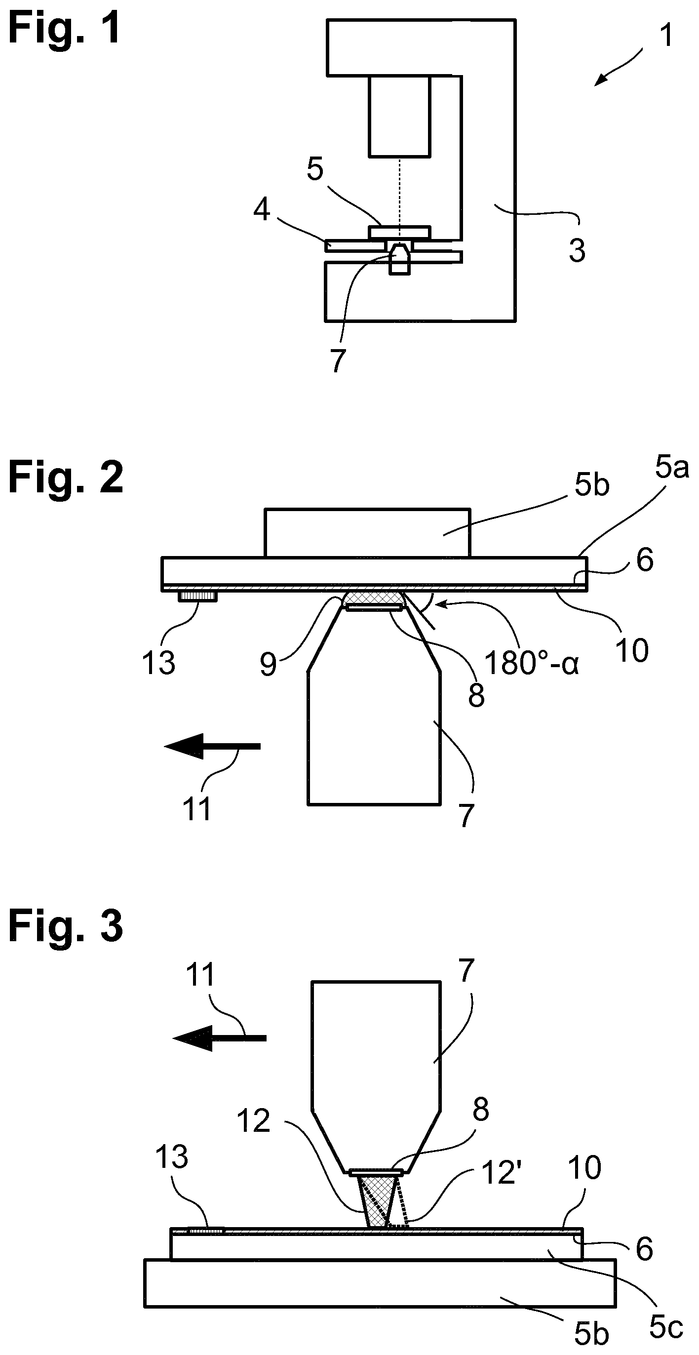
[0018] FIG. 1 shows a schematic illustration of an inverted microscope,
[0019] FIG. 2 shows an enlarged detail of the illustration of FIG. 1,
[0020] FIG. 3 shows the conditions of a microscope with an elastomeric immersion medium in the case of erect microscopy, and
[0021] FIG. 4A-4B show various options of applying a coating to a sample carrier or a cover slip.
DETAILED DESCRIPTION
[0022] FIG. 1 schematically shows a microscope 1, which comprises a nosepiece 2 in a base of a limb 3. A sample stage 4, on which a sample 5 is disposed, is also situated on the limb 3. An illumination device illuminates the sample 5 from above, an objective 7 held in the nosepiece 2 images the illuminated sample 5 from its surface 6 facing the objective (cf. FIG. 2).
[0023] FIG. 2 shows an enlarged view of the relationships between the objective 7 and the sample 5, the latter consisting of a sample carrier 5a, in this case a Petri dish, with, lying thereon, sample substance 5b.
[0024] The objective 7 comprises a front lens 8, on which an immersion liquid 9 is applied. The immersion liquid is selected appropriately depending on the application, i.e., the sample. In general, the objective 7 is designed for a specific immersion liquid. The immersion liquid 9 is located in a gap between the sample carrier 5a and the front lens 8 of the objective 7. The objective 7 and sample carrier 5a are displaced relative to one another, which is visualized in FIG. 2 by an arrow 11. The objective 7 is displaced in this exemplary embodiment. It is equally possible to move the sample carrier 5a or both. Additionally, the objective 7 can image the sample 5b via a cover slip. So that the immersion liquid 9 does not smear on the sample carrier 5a during the displacement along the arrow 11 and thus is lost from the gap between front lens 8 and sample carrier 5a, the surface 6 of the sample carrier 5a facing the objective 7 is provided with a coating 10, which has a repellent effect on the immersion medium 9. If the immersion medium 9 is water-based, use can be made of a hydrophobic coating 10, for example. A lipophobic coating 10 can be used in the case of oil-based immersion liquids. An embodiment in which an omniphobic coating 10 i.e., a coating that is both lipophobic and hydrophobic is used is particularly preferred. Such a coating is suitable for all possible types of sample carriers 5a, e.g., also for a membrane or a sample receiving vessel. In order to identify the surface 6 that is provided with the coating 10, the sample carrier 5a optionally has a marking 13 when said sample carrier has a symmetric embodiment, e.g., as a glass mount, the marking being applied to the coating 10 in the embodiment illustrated in FIG. 2 and allowing an identification of the coated surface. This is advantageous in that the coating 10 is one-sided and not disposed on the surface of the sample carrier 5a on which the sample substance 5b lies. Consequently, an interaction between the coating 10 and the sample substance 5b is precluded. As a rule, it would be disadvantageous since the type of immersion liquid, as a rule, equals the type of sample substance 5b. A water-based immersion medium 9 is required for aqueous samples 5b or samples 5b mounted in aqueous media. The coating 10 is then at least hydrophobic (or omniphobic) and would also repel the aqueous sample 5b in the case of a two-sided application on the sample carrier 5a/the cover slip. An analogous statement applies to an oil-containing sample 5b.
[0025] The effect of the coating 10 is that the immersion liquid 9 is repelled at the surface 6 on which the coating 10 has been applied. FIG. 2 elucidates this by a contact angle .alpha. of more than 90.degree. (the counter angle 180.degree.-.alpha. is plotted in the figure).
[0026] FIG. 3 shows the conditions in the case of an erect microscope, wherein, additionally, an elastomeric immersion is used as an immersion medium. Here, the sample 5b is covered by a cover slip 5c, the surface 6 of which pointing to the objective 7 likewise being provided with the coating 10, which is omniphobic in this exemplary embodiment. This coating prevents the elastomeric immersion from being deformed in the way indicated by the dashed form 12' during the relative displacement along the arrow 11. Such a deformation would occur if the repulsive coating 10 would be missing. Shown here, too, in exemplary fashion is that the marking 13 can be applied not only to the coating 10 but can also be provided in the coating 10. Equally, it is possible to provide the marking 13 on the opposite side. All that is important is that the marking 13 allows identification of the side on which the coating 10 that is only provided on one side is applied.
[0027] The coating 10 used during microscopy can already be stored on the sample carrier or the cover slip, as shown in FIGS. 2 and 3. In embodiments, it is equally possible to apply the coating only within the scope of the production of the preparation which is to be examined by microscopy. FIGS. 4A and 4B show possibilities to this end. In FIG. 4A, the coating 10 is applied from the liquid phase using an applicator 14, which comprises a roller 15 that has been wetted with a liquid substance, the substance forming the coating 10 following the application. The applicator 14 is guided along the arrow 16 over the surface 6 of the cover slip 5c or of the sample carrier 5a in such a way that the roller 15 rolls over the surface 6 and applies the coating 10 in the process. The roller 15 is continuously wetted with the substance in the applicator 14.
[0028] FIG. 4B shows an applicator 14 that is embodied in the style of a felt tip pen. By way of an application element 17, which is fed from a reservoir provided in the applicator 14, the coating 10 is applied to the surface 6 of the cover slip 5c.
[0029] Consequently, in embodiments of the microscopy method, the sample 5a is firstly applied to a sample carrier 5a and covered by a cover slip 5c where necessary, and then the surface 6, which will subsequently lie opposite the microscope objective 7, is provided with the coating 10. To this end, the applicators of FIGS. 4A and 4B are some of a plurality of options. A further option would lie in the spraying-on of a substance that forms the coating 10, the application with a coating cloth, etc.
* * * * *
D00000
D00001
D00002
XML
uspto.report is an independent third-party trademark research tool that is not affiliated, endorsed, or sponsored by the United States Patent and Trademark Office (USPTO) or any other governmental organization. The information provided by uspto.report is based on publicly available data at the time of writing and is intended for informational purposes only.
While we strive to provide accurate and up-to-date information, we do not guarantee the accuracy, completeness, reliability, or suitability of the information displayed on this site. The use of this site is at your own risk. Any reliance you place on such information is therefore strictly at your own risk.
All official trademark data, including owner information, should be verified by visiting the official USPTO website at www.uspto.gov. This site is not intended to replace professional legal advice and should not be used as a substitute for consulting with a legal professional who is knowledgeable about trademark law.