Laser scanner for monitoring a monitoring region
VAN LOO; Sebastien ; et al.
U.S. patent application number 16/623365 was filed with the patent office on 2020-06-11 for laser scanner for monitoring a monitoring region. The applicant listed for this patent is BEA SA. Invention is credited to Theodoros CAMPAS, Jean-Francois KLEIN, Marc MEYERS, Sebastien VAN LOO.
| Application Number | 20200183005 16/623365 |
| Document ID | / |
| Family ID | 62837853 |
| Filed Date | 2020-06-11 |

| United States Patent Application | 20200183005 |
| Kind Code | A1 |
| VAN LOO; Sebastien ; et al. | June 11, 2020 |
Laser scanner for monitoring a monitoring region
Abstract
Laser scanner monitors region in front of an opening. Monitoring region is delimited by a frame, in front of which an edge region is located. Propagation time sensing means determines position of an object in the monitoring region by a propagation time measurement of laser pulse, an evaluation unit being provided, by means of which first object information is produced, whether an object was sensed by the propagation time measurement. An intensity sensing means evaluating received laser pulse with respect to the intensity thereof and the sensed intensity is compared with a reference intensity stored in a memory unit. Second object information being provided in the event of deviation beyond a certain threshold value, whether an object is located in the hazard edge region on the basis of the intensity deviation. A "safety signal" generated by the evaluation unit if first or second object information is positive.
| Inventors: | VAN LOO; Sebastien; (Vaux-et-Borset, BE) ; MEYERS; Marc; (Seraing, BE) ; CAMPAS; Theodoros; (Boncelles, BE) ; KLEIN; Jean-Francois; (Eupen, BE) | ||||||||||
| Applicant: |
|
||||||||||
|---|---|---|---|---|---|---|---|---|---|---|---|
| Family ID: | 62837853 | ||||||||||
| Appl. No.: | 16/623365 | ||||||||||
| Filed: | June 15, 2018 | ||||||||||
| PCT Filed: | June 15, 2018 | ||||||||||
| PCT NO: | PCT/EP2018/065988 | ||||||||||
| 371 Date: | December 16, 2019 |
| Current U.S. Class: | 1/1 |
| Current CPC Class: | G01S 7/487 20130101; E05F 15/73 20150115; G01S 17/46 20130101; E05F 2015/765 20150115; G01S 17/42 20130101; E05Y 2400/456 20130101; G01S 17/88 20130101; E05F 15/74 20150115; E05Y 2400/852 20130101; E05Y 2900/132 20130101; G01S 17/10 20130101; E05Y 2900/148 20130101 |
| International Class: | G01S 17/10 20060101 G01S017/10; G01S 17/88 20060101 G01S017/88; E05F 15/73 20060101 E05F015/73 |
Foreign Application Data
| Date | Code | Application Number |
|---|---|---|
| Jun 16, 2017 | DE | 102017113237.6 |
Claims
1-10. (canceled)
11. Laser scanner (10, 32) for monitoring a monitoring region (36) in front of an opening that can be closed by a closing means, the design of which closing means defines a hazard region (40) in the monitoring region (36), the monitoring region (36) being delimited at least on one side by a frame (34), in front of which an edge region (38), comprising a laser transmitting/receiving unit (12), furthermore a propagation time sensing unit (14) being provided which determines the position of an object (22, 44, 46) in the monitoring region (36) by means of a time of flight measurement (TOF(RP) of a transmitted and received laser pulse, an evaluation unit (18) being provided by means of which first object information is produced, namely whether an object was sensed in a hazard edge region (42) by the propagation time measurement, furthermore an intensity sensing means (16) being provided, by means of which the received laser pulse is evaluated with respect to its intensity (1(RP)) and the detected intensity (1(RP)) is compared with a reference intensity (I.sub.REF) stored in a memory unit (24), second object information being provided in the event of deviation beyond a certain threshold value (D), if the propagation time sensing means (14) does not detect any object in the hazard region (40) outside the hazard edge region (42), namely, on the basis of the intensity deviation, whether an object is located in the hazard edge region (42), and a "safety" signal being generated by the evaluation unit (18) if either the first or the second object information is positive.
12. Laser scanner according to claim 1, characterized in that the laser transmitting/receiving unit (12) comprises an avalanche photodiode.
13. Laser scanner according to claim 1, characterized in that the intensity sensing (16) is performed by means of pulse width evaluation.
14. Laser scanner according to claim 1, characterized in that an initialization device is provided which enables an initialization of the laser scanner, with the reference intensity (I.sub.REF) of a frame (34) in the monitoring region (36) being stored in the memory unit (24) during initialization.
15. Laser scanner according to claim 4, characterized in that the monitoring region (36), the hazard region (40), the edge region (38) and the hazard edge region (42) are defined during initialization.
16. Arrangement (30) comprising an at least partially circumferential frame, a closing means for closing the opening formed by the frame (34), and a laser scanner (32) according to claim 1, the laser scanner (32) being mounted on the frame in such a way that the frame (34) at least partially delimits the monitoring region (36) of the laser scanner (32).
17. Arrangement according to claim 6, characterized in that the sensor (32) is mounted in the corner portion of the frame (32).
18. Arrangement according to claim 6, characterized in that the frame (34) is part of a window or a window reveal.
19. Arrangement according to one of claims 6, characterized in that the closing means is controlled by a control unit that is connected to the laser scanner.
20. Arrangement according to one of claims 6, characterized in that the closing means is a window.
21. Laser scanner according to claim 2, characterized in that the intensity sensing (16) is performed by means of pulse width evaluation.
22. Laser scanner according to claim 2, characterized in that an initialization device is provided which enables an initialization of the laser scanner, with the reference intensity (I.sub.REF) of a frame (34) in the monitoring region (36) being stored in the memory unit (24) during initialization.
23. Laser scanner according to claim 3, characterized in that an initialization device is provided which enables an initialization of the laser scanner, with the reference intensity (I.sub.REF) of a frame (34) in the monitoring region (36) being stored in the memory unit (24) during initialization.
24. Arrangement (30) comprising an at least partially circumferential frame, a closing means for closing the opening formed by the frame (34), and a laser scanner (32) according to claim 2, the laser scanner (32) being mounted on the frame in such a way that the frame (34) at least partially delimits the monitoring region (36) of the laser scanner (32).
25. Arrangement (30) comprising an at least partially circumferential frame, a closing means for closing the opening formed by the frame (34), and a laser scanner (32) according to claim 3, the laser scanner (32) being mounted on the frame in such a way that the frame (34) at least partially delimits the monitoring region (36) of the laser scanner (32).
26. Arrangement according to claim 7, characterized in that the frame (34) is part of a window or a window reveal.
27. Arrangement according to one of claims 7, characterized in that the closing means is controlled by a control unit that is connected to the laser scanner.
28. Arrangement according to one of claims 7, characterized in that the closing means is a window.
29. Arrangement according to one of claims 8, characterized in that the closing means is a window.
30. Arrangement according to one of claims 9, characterized in that the closing means is a window.
Description
[0001] The invention relates to a laser scanner for monitoring a monitoring region in front of an opening that can be closed by a closing means, as well as to an arrangement comprising at least a laser scanner and a frame member that delimits the monitoring region.
[0002] Laser scanners for automatic doors and windows are known in the prior art. In the prior art manner, these laser scanners include propagation time sensing means for determining a distance from the laser scanner and for making an assignment to a monitoring region. In this process, individual laser pulses, each assigned to an angle and emitted by the laser scanner, are reflected by an object. The reflection is evaluated by means of propagation time measurement. This allows the position of an object to be detected in the monitoring region. If such position is in a region defined as a hazard region, a so-called "safety" signal will routinely be sent to a control unit in order to prevent an object from being trapped in the automatic closing means, in particular a door or a window. A positive "safety" signal will routinely cause the control unit of the closing means to stop or to reverse the closing movement.
[0003] It is disclosed in DE 10 2006 043 615 DE that a laser scanner having a transmitting unit and a receiving unit can be used to detect an object in a monitoring region. The received signal is compared with a reference signal, which reference signal may be correlated with a door movement. A comparison is made both for the propagation time measurement and for the reflectivity measurement.
[0004] It is the object of the invention to achieve an as reliable as possible detection of a vulnerable object in the hazard region "safety" region. High reliability shall also be ensured when the hazard region is located in the vicinity of a frame that delimits the monitoring region. This is to apply to small objects in particular.
[0005] This object is accomplished by the characterizing features of claim 1.
[0006] Disclosed in the dependent claims are advantageous further embodiments of the invention.
[0007] According to the invention, a laser scanner for monitoring a monitoring region in front of an opening that can be closed by a closing means is designed as described below. Using an evaluation unit, the laser scanner determines the position of an object in the monitoring region by measuring the propagation time of a transmitted and received laser pulse. The monitoring region comprises at least one hazard region, and when an object is detected in said hazard region, the laser scanner will output a "safety" signal. If no object is detected in the hazard region outside the hazard edge region, first object information will be generated based on the propagation time measurement, namely whether an object was sensed in the hazard edge region by means of the propagation time measurement. Furthermore, the intensity of the received laser pulse will be evaluated and the sensed intensity will be compared with a reference intensity stored in a memory unit of the laser scanner. In the event of deviation beyond a certain threshold value, second object information will be provided, namely whether, based on the intensity deviation, an object is located in the hazard edge region. The hazard edge region is the region in the vicinity of which the monitoring region is physically delimited by a frame and which is moreover defined as a hazard region.
[0008] A distance from an edge region which is obtained in the vicinity of the frame that delimits the monitoring region at least on one side, in particular on two sides, is to be determined. The problem about the edge region is that the accuracy of the propagation time measurement in the edge region is only possible inaccurately. This makes it difficult to detect small objects in this region. The region in which no reliable distinction can be made between a small object and the background formed by the frame is called the gray area. The accuracy of the propagation time measurement which is captured by means of the reflected light pulse, also depends on the difference in the degree of reflectivity of the object with respect to the background.
[0009] On the basis of the received intensity, an error correction of the propagation time measurement can also be performed to allow a more accurate evaluation of the position.
[0010] A major difference in reflectivity will result in a high deviation that will affect the size of the gray area in the edge region of the frame.
[0011] The invention proposes that an intensity comparison be performed between the background and the current object measurement. If the deviation of the measured intensity exceeds a predefined threshold value, a detection will be reported, even if a propagation time measurement does not produce a detection result within the frame.
[0012] The intensity deviation is the amount of the difference between the reference intensity and the object intensity.
[0013] In this way, the inaccuracy of the propagation time measurement in the gray area in the region of an edge can be eliminated. This ensures high detection reliability even for small objects.
[0014] In a scanning operation, the laser scanner uses laser pulses distributed in a sector to scan a plane which, in its projection, covers the opening to be monitored, and which, in particular, is parallel to the opening plane.
[0015] The intensity is measured by evaluating the received pulse width. The detector used is an avalanche photodiode.
[0016] Preferably, the intensity is averaged over several successive laser pulses for a point, and a mean value is formed which is compared with a reference mean value.
[0017] The reference intensity is recorded during initial operation and in cycles, if necessary, and stored in the memory unit. The reference intensity can be corrected by the laser pulses detected during the measurement. In particular, a correction is made during each measurement in which no detection is made for the measured laser pulse. This allows continuous adaptation to changes in the environment.
[0018] If first object information is provided that represents an object in the monitoring region, a "safety" signal will be output at the laser scanner output.
[0019] If second object information is provided simultaneously that represents an object in the monitoring region, a comparison with the approximately simultaneous object information will be carried out.
[0020] The sensor comprises an electronic evaluation unit for evaluating propagation time and intensity. The evaluation unit furthermore includes a filter, with the filter properties affecting the size of the gray area.
[0021] It is also possible for the monitoring region to include, in addition to the hazard edge region, other detection regions which may, for example, trigger activation. For these regions, provision can be made to only take an object in such a region into account for the propagation measurement. This results in a more robust detection behavior of the laser scanner. For the hazard region, the intensity measurement will therefore not be taken into account unless it is an edge region.
[0022] As a rule, the size of the defined edge region is approx. 2 cm to 5 cm. This size depends, among other things, on the filters used to evaluate the propagation time information. According to another aspect of the invention, the invention relates to an arrangement comprising an at least partially circumferential frame, a closing means for closing the opening formed by the frame, and a laser scanner as previously described, said laser scanner being mounted on the frame in such a manner that the frame will at least partially delimit the monitoring region of the laser scanner.
[0023] The laser scanner is preferably mounted in a corner of the frame.
[0024] Furthermore, the arrangement may comprise a control unit for controlling the closing means, in particular a window, which cooperates with the laser scanner.
[0025] Additional advantages, features and possible applications of the present invention may be gathered from the following description in which reference is made to the embodiments illustrated in the drawings.
[0026] Throughout the description, claims and drawings, those terms and associated reference signs are used as are specified in the list of reference signs below. In the drawings:
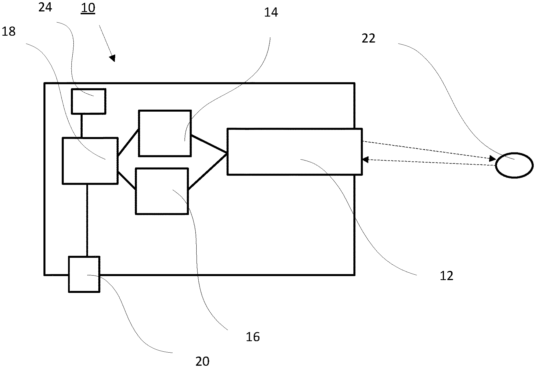
[0027] FIG. 1 is a laser scanner according to the invention;
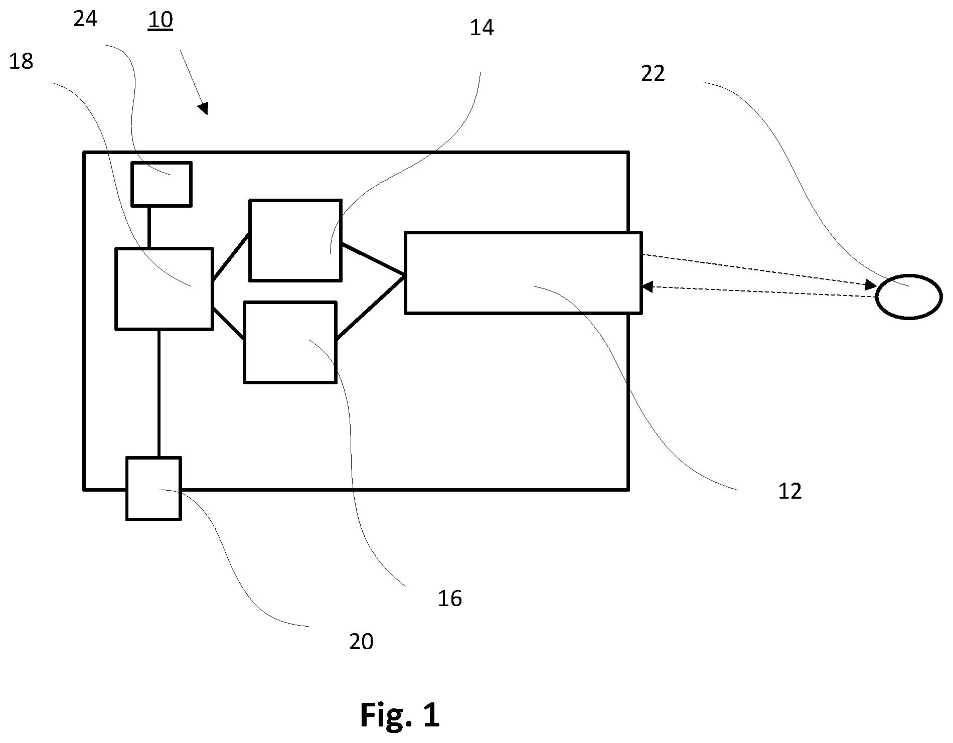
[0028] FIG. 2 is schematic view of an arrangement according to the invention where there is no object in the detection region;
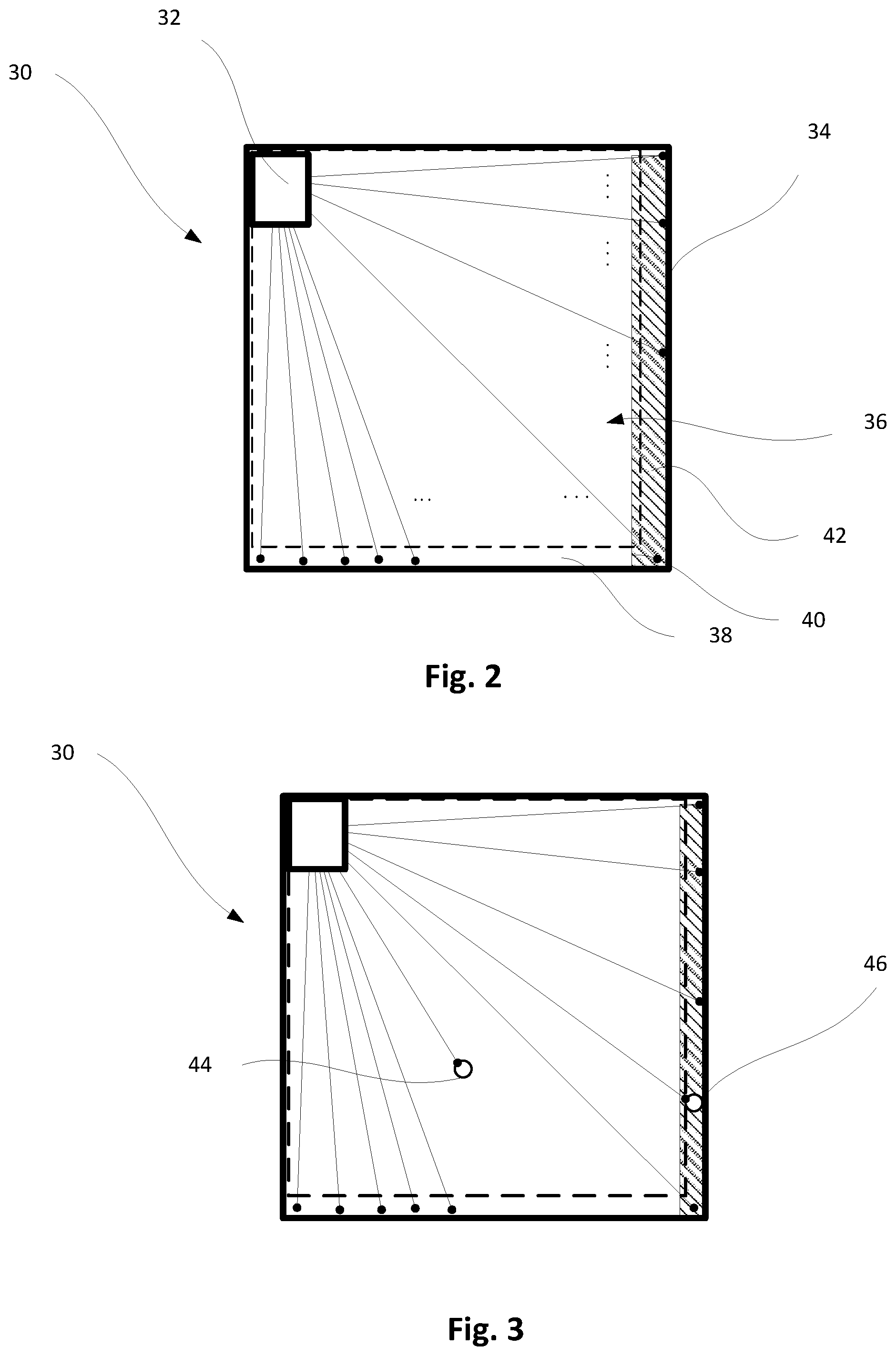
[0029] FIG. 3 is a schematic view of an arrangement according to invention where there is an object in the detection region and in the edge region, and
[0030] FIG. 4 is a schematic flow chart.
[0031] Fig.1 shows a laser scanner 10 according to the invention having a laser scanner transmitting and receiving unit 12 capable of transmitting laser pulses over an angular range and of receiving the laser pulses reflected by an object 22. The received laser pulses are then analyzed in a propagation time sensing means 14 and an intensity sensing means 16. Furthermore, an evaluation unit 18 is provided which makes a decision--based on the values generated by the propagation time sensing means 14 and the intensity sensing means 16--as to whether a positive "safety" signal is to be output at the "safety" output 20, whereby a control unit can be set to a safety mode. For evaluation, the evaluation unit 18 uses reference values that are stored in a memory unit 24. The exact function of the evaluation unit will be described in more detail with reference to FIG. 4.
[0032] FIG. 2 shows an arrangement 30 according to the invention, comprising a frame 34 and a laser scanner designed as a laser scanner 32. The laser scanner 32 emits laser pulses that can be reflected by an object in a monitoring region 36 or a frame 34 delimiting the monitoring region.
[0033] The propagation time from the emission of the laser pulse to the detection of the reflection is determined. The propagation time can be used to detect the position of an object within the frame 34 in the monitoring region 36. Owing to the accuracy of the propagation time measurement for small objects, this type of detection reaches its limits in the edge region 38 of the monitoring region 36 near the frame 34.
[0034] The edge region 38, delimited by the dashed line in the drawing, extends from the lower edge over the right edge of the frame 34 and is also considered a hazard region 40 at the right edge. In this region, the edge region 38 represents a hazard edge region 42 which is to be evaluated in a reliable manner.
[0035] According to the invention, in addition to the propagation time, also the intensity of the reflected laser pulse is evaluated in the hazard edge region 42. The evaluation is carried out as described in more detail with reference to FIG. 4, by determining the reference values of frame 34 for each laser pulse in an initialization cycle. The sensed intensity is compared to the reference intensity stored in the laser scanner 32. If the deviation exceeds a predefined threshold value, a "safety" signal will be sent to the control unit to control the closing means (not shown here for reasons of clarity), in particular the window, with the result that a potential closing process will be interrupted.
[0036] FIG. 3 shows the arrangement 30 of FIG. 2, with two objects 44, 46 being illustrated in this case, of which object 44 is detected by means of the propagation time measurement and object 46 can be detected in an evaluation of the hazard edge region taking into account the intensity measurement, although the propagation time measurement in the gray zone does not permit an unambiguous evaluation. To measure the intensity of the laser pulse, the pulse width of the received laser pulse is evaluated.
[0037] FIG. 4 shows a flow chart for detecting sensing an object that is detected in a hazard edge region. A propagation time measurement is performed, which is also referred to as time of flight (TOF) measurement. Using the propagation time of the laser pulse, the distance of a point off which the laser pulse is reflected is assigned to a position in the monitoring region, or is discarded if it is outside the monitoring region.
[0038] Depending on the design of the closing means, there is a hazard region which is assigned to the monitoring region. Thus a hazard region is defined in the monitoring region, if an object is detected in the hazard region, a so-called "safety" signal will be output by the evaluation unit.
[0039] If the monitoring region is delimited by a physical frame in the hazard region, this will result in a hazard edge region. In this edge region, an evaluation of the propagation time measurement cannot always be carried out with sufficient accuracy to allow the detection of a small object.
[0040] During initial operation of the laser scanner, in an initialization run thereof, the position of the edge region is detected by means of a TOF measurement and its reflectivity is measured by means of the reflected laser pulse, which is stored as a reference value for the corresponding measuring point in a memory of the laser scanner.
[0041] Therefore, when the TOF measurement is evaluated, it is decided whether the value of the TOF distance measurement is greater than the distance from the defined hazard edge region.
[0042] If this is the case, a hazard edge region evaluation is carried out. During such hazard edge region evaluation, besides first object information obtained from the TOF measurement, second object information is produced. The second object information shows whether a deviation of the reflectivity of the currently measured laser pulse is greater than the measured value of an assigned reference reflectivity, which reflects the reflectivity of the frame. The reflectivity is evaluated as a function of the intensity of the received laser pulse, and
[0043] is determined from the pulse width. If the amount of the difference between intensity and reference intensity is above the threshold value D, the second object information provided will be positive, otherwise negative.
[0044] If the value of the TOF measurement of the reflected point lies in the hazard edge region, the first object information provided will also be positive, otherwise negative.
[0045] The evaluation unit will output a positive "safety" signal if the first object information or the second object information is positive.
[0046] In this way, in the edge region, where particularly large inaccuracies occur in the TOF measurement when there is a large difference between the reflectivity of the object and the frame behind ft can be largely eliminated by using the intensity information for this purpose.
[0047] Consequently, even small objects will be detected in the hazard region.
[0048] If the deviation of the intensity is less than the threshold value D, the stored reference reflectivity is corrected with this value.
LIST OF REFERENCE SIGNS
[0049] 10 laser scanner
[0050] 12 laser scanner transmitting/receiving unit
[0051] 14 propagation time sensing means
[0052] 16 intensity sensing means
[0053] 18 evaluation unit
[0054] 20 "safety" output
[0055] 22 object
[0056] 24 memory
[0057] 30 arrangement
[0058] 32 laser scanner
[0059] 34 frame
[0060] 36 monitoring region
[0061] 38 edge region
[0062] 40 hazard region
[0063] 42 hazard edge region
[0064] 44 first object
[0065] 46 second object
[0066] D threshold
* * * * *
D00000
D00001
D00002
D00003
XML
uspto.report is an independent third-party trademark research tool that is not affiliated, endorsed, or sponsored by the United States Patent and Trademark Office (USPTO) or any other governmental organization. The information provided by uspto.report is based on publicly available data at the time of writing and is intended for informational purposes only.
While we strive to provide accurate and up-to-date information, we do not guarantee the accuracy, completeness, reliability, or suitability of the information displayed on this site. The use of this site is at your own risk. Any reliance you place on such information is therefore strictly at your own risk.
All official trademark data, including owner information, should be verified by visiting the official USPTO website at www.uspto.gov. This site is not intended to replace professional legal advice and should not be used as a substitute for consulting with a legal professional who is knowledgeable about trademark law.