Device And Method For Determining The Weight Of A Hydraulic Accumulator
KLOFT; Peter ; et al.
U.S. patent application number 16/341101 was filed with the patent office on 2020-06-11 for device and method for determining the weight of a hydraulic accumulator. The applicant listed for this patent is HYDAC TECHNOLOGY GMBH. Invention is credited to Herbert BALTES, Peter KLOFT.
| Application Number | 20200182683 16/341101 |
| Document ID | / |
| Family ID | 59761917 |
| Filed Date | 2020-06-11 |


| United States Patent Application | 20200182683 |
| Kind Code | A1 |
| KLOFT; Peter ; et al. | June 11, 2020 |
DEVICE AND METHOD FOR DETERMINING THE WEIGHT OF A HYDRAULIC ACCUMULATOR
Abstract
The invention relates to a device for determining the weight of a hydraulic accumulator (10) during the operation thereof in a hydraulic facility, where a pressurised liquid is introduced into a pressure vessel at least partially filled with a gas, said pressurised liquid compressing the gas and being stored in such a way that when it leaves the accumulator (10), hydraulic energy is emitted to the facility, and where the respective current weight of the hydraulic accumulator (10) is detected by means of a weighing device (14) applied to the hydraulic accumulator (10).
| Inventors: | KLOFT; Peter; (Ransbach-Baumbach, DE) ; BALTES; Herbert; (Losheim, DE) | ||||||||||
| Applicant: |
|
||||||||||
|---|---|---|---|---|---|---|---|---|---|---|---|
| Family ID: | 59761917 | ||||||||||
| Appl. No.: | 16/341101 | ||||||||||
| Filed: | September 4, 2017 | ||||||||||
| PCT Filed: | September 4, 2017 | ||||||||||
| PCT NO: | PCT/EP2017/001042 | ||||||||||
| 371 Date: | April 11, 2019 |
| Current U.S. Class: | 1/1 |
| Current CPC Class: | G01G 17/04 20130101; G01G 19/00 20130101; G01G 21/28 20130101; G01L 19/0023 20130101; G01L 9/006 20130101 |
| International Class: | G01G 17/04 20060101 G01G017/04; G01L 19/00 20060101 G01L019/00 |
Foreign Application Data
| Date | Code | Application Number |
|---|---|---|
| Oct 14, 2016 | DE | 10 2016 012 621.3 |
Claims
1. A device for determining the weight of a hydraulic accumulator (10) during operation within a hydraulic plant, in which a pressurized liquid is introduced into a pressure vessel that is at least partially filled with gas, in which the gas is compressed and the liquid is stored under pressure in such a way that, at its discharge from the accumulator (10), hydraulic energy is released to the plant, and in which the current weight of the hydraulic accumulator (10) is determined by a weighing device (14) that engages with the hydraulic accumulator (10).
2. The device according to claim 1, characterized in that the weighing device (14) is provided with a seat (18) that surrounds the housing (16) of the hydraulic accumulator (10) at least partially, or onto which the hydraulic accumulator (10) can be seated with its bottom end, and that the seat (18) interacts with a measuring facility for determining the weight of the hydraulic accumulator (10).
3. The device according to claim 1, characterized in that the measuring facility comprises at least one load cell (22) with a bending beam (24) and at least one strain gauge disposed thereon.
4. The device according to claim 1, characterized in that the measuring facility is connected to a signal amplifier for the purpose of visualizing its measuring result.
5. The device according to claim 1, characterized in that the load cell (22) is designed as double bending beam made from a metallic material of preferably rectangular cross-section.
6. The device according to claim 1, characterized in that disposed on the upper side of the respective load cell (22) is the collar together with the associated components for supporting the hydraulic accumulator (10).
7. The device according to claim 1, characterized in that the seat (18) takes the form of a support ring (28), on which the bottom end of the hydraulic accumulator (10) rests and at least partially engages with the opening of said support ring (28), and that the support ring (28) is supported by at least three sensing columns (34) that are disposed at a distance from each other, which stand on three associable load cells (22) that are braced at the bottom against an equipment ring (32), which is firmly attached to the load cells (22).
8. The device according to claim 1, characterized in that the respective support ring (28) surrounds a passage opening in such a way that liquid-conducting tube can be connected to the pressure vessel on the liquid side of the hydraulic accumulator (10).
9. A method for the implementation of a weight measurement on a hydraulic accumulator to determine the present gas volume at the gas side of the hydraulic accumulator (10), in which it is determined, based upon a reference value for the stored gas volume, how the said stored gas volume diminishes if, at a predeterminable operating state of the hydraulic accumulator (10) the volume of the liquid in the liquid side of the hydraulic accumulator (10) increases.
10. A method for the implementation of a piston position measurement in a piston accumulator (12) by means of a weight measurement for determining the respective current piston position wherein, based upon a reference value for a predetermined piston position, how said piston position changes if, at a predeterminable operating state of the piston accumulator (12) the gas volume in the gas side diminishes and the volume of the liquid in the liquid side of the piston accumulator (12) increases.
Description
[0001] The invention concerns a device for determining the weight of a hydraulic accumulator during operation within a hydraulic plant, in which a pressurized liquid is introduced into a pressure vessel that is partially filled with gas, in which the gas is compressed and the liquid is stored under pressure in such a way that, at its discharge from the accumulator, hydraulic energy is released to the plant, and in which the weight of the hydraulic accumulator is determined by a weighing device that engages with the hydraulic accumulator. The invention concerns, moreover, a method for implementing the determination of the weight, preferably by application of such a device.
[0002] With hydropneumatic accumulators or hydraulic accumulators it has so far been necessary to check the pressure level of the gas required for the correct operation of such an accumulator at certain time intervals since, depending on the operating mode of the respective hydraulic accumulator, gas losses are likely to occur. To this end it is possible to fully release the pressure from the hydraulic plant on the so-called liquid side or oil side, at least from that part of the plant to which the hydraulic accumulator is connected, to be able to check, in said pressure-free state, the pre-load pressure of the gas inside the hydraulic accumulator, often in form of nitrogen gas, and to replenish any missing quantities on the gas-side of the accumulator if necessary. This process is, however, time-consuming and the hydraulic accumulator plant is not operational for the duration of said test.
[0003] To overcome said disadvantages, the document DE 43 20 383 C2 proposes a device for measuring the actual gas pre-load pressure of a gas in a hydropneumatic accumulator, which provides a gas connection between the accumulator and a measuring chamber that is a fraction of the size of the accumulator volume, wherein said measuring chamber may be shut off, and where a measuring sensor is disposed between the accumulator and the shut-off device, making it possible to measure the gas pressure inside the accumulator when the connection is shut off as well as to measure the resulting change in pressure when the connection is opened. The actual gas pre-load pressure may then be calculated from the pair of measuring values obtained in this manner. This makes it possible to determine the actual gas pre-load pressure using a simple design and a single measuring process, which in turn allows for a judgement concerning the operational state of the accumulator. That is because if the actual gas pre-load pressure that was determined through the measurement is either less or greater with respect to a target gas pre-load pressure, the accumulator has to be charged or discharged respectively at its gas end with a predeterminable quantity of gas via a corresponding dosing device to ensure the operational reliability of the hydraulic accumulator. However, since in the known solution the operating gas or stored gas in the hydraulic accumulator necessarily expands when flowing into the connected measuring chamber for a measuring operation, temperature differences occur between the stored gas and the gas to be measured, which has a negative effect on the measuring quality.
[0004] Moreover, the document DE 42 27 657 A1 discloses an ultrasonic measuring device for a hydraulic accumulator in form of a piston accumulator, which serves to ascertain the predeterminable target position of the piston that is displaceable inside the accumulator housing, wherein said piston serves as the separating element between the gas side and the liquid side of the accumulator. The piston is provided with at least one measuring element that is detectable by the measuring device, wherein a visible marker is assigned to said measuring element that indicates the target position of the piston on the outside of the accumulator housing. With respect to said accumulator housing marker, an ultrasonic measuring device, which is provided for the respective measuring element on the piston, may be placed onto the accumulator or pressure vessel housing, which makes it possible to measure a plurality of different accumulators of a certain size and said markings with a single measuring device, which limits the instrumentation requirements for the measurements.
[0005] Since the position of the piston inside the piston accumulator can be equated with a certain, predeterminable filling volume at the gas side of the hydraulic accumulator, it is possible to check a plurality of accumulators concerning compliance with a predeterminable target gas pressure by using a single, hand-held unit as measuring device, wherein said target gas pressure corresponds to the original gas pre-load pressure of the accumulator when it was first supplied or taken into operation. If the actual gas pressure value deviates from the target value, that is, the actual value is less than the target value, the separating piston of the piston accumulator is displaced towards the reduced gas volume due to the increased amount of liquid streaming in and thus placing the piston outside the marker, which is detected by the ultrasonic measuring device and thereby provides the opportunity to replenish the accumulator at its gas side until the piston is back in its predeterminable target position that is indicated by the respective marker so that the full functionality of the hydraulic accumulator is restored again in this manner.
[0006] Since the above-described measuring device must be operated manually, and possibly a large number of hydraulic accumulators may need to be checked, this causes a significant manual measuring effort, reflected in high expenses.
[0007] Based upon said prior art it is the object of the invention to provide a device and method with which it is possible to ascertain the functional reliability of a hydraulic accumulator at a small effort and free of measuring errors.
[0008] Said object is met by a device that bears the characteristics of claim 1 in its entirety as well as a method according to the characteristics described in claims 9 and 10.
[0009] According to the characteristics of claim 1, the weight of the hydraulic accumulator is measured, preferably continuously, even whilst in operation inside a hydraulic plant to which it is connected, by means of a separate weighing device that engages with the respective hydraulic accumulator. The weighing device that engages with the respective hydraulic accumulator constantly or permanently may at the beginning, when the hydraulic accumulator is not charged with a liquid, such as a hydraulic medium for example, or is only partially charged, determine its empty weight. Once the empty weight of the respective hydraulic accumulator of a certain volume class has been determined, it is known from prior measurements or from practical experience how much liquid such an accumulator is able to take up so that it can be pre-loaded with a predeterminable gas pressure at the gas side of the hydraulic accumulator to be able to fulfill its function reliably. When considering this it is also feasible to utilize a reference hydraulic accumulator with a functional "operating weight" that is known. If the hydraulic accumulator is now in operation in the plant to which it is connected, it will, in the long run at least, lose gas from the gas side towards the liquid side, for example due to permeation or other leakage of the respective separating element that separates the gas side from the liquid side. The consequence of this is that the actual gas pre-load pressure drops below the target pressure, which causes more liquid to enter into the accumulator, which the weighing device connected to the hydraulic accumulator senses immediately. If any predeterminable, intolerable mass limits are exceeded, the respective hydraulic accumulator will have to be replaced altogether, or its gas side has to be replenished as part of the maintenance process.
[0010] Due to the possibility of a continuous weight measurement of the accumulator it is possible to recognize developing trends, which make it possible to determine at what stage the functional reliability of the hydraulic accumulator is no longer provided. In extreme instances the separating element of the hydraulic accumulator, which often is provided in form of an elastomeric membrane or an accumulator bladder, could rip, or the separating piston could start leaking around the circumference. The result of a failure of this kind would be that the hydraulic accumulator loses its entire volume of gas in the direction of the liquid side, and the liquid starts to completely fill the pressure vessel or the accumulator housing during operation of the accumulator, which is something that the weighing device senses immediately and reliably due to the rapidly increasing weight of the accumulator due to the weight of the liquid. In particular hydraulic accumulators that are used for emergency functions in plants used for example in nuclear power stations, it is in this way possible to monitor the required functional reliability over longer operating periods by means of the weighing device. This constitutes an important gain in reliability.
[0011] To achieve particularly accurate measurements, the weighing device may be connected to a higher-level electronic control and monitoring unit, which also receives pressure and/or temperature inputs, so that, based on the usual gas equations of state, the determined weights can be recalculated to exactly the liquid and gas volumes introduced into the respective hydraulic accumulator. Since the hydraulic accumulator constitutes a closed system it is sufficient to regularly sense the pressure and/or temperature values at the liquid side of the accumulator since, at least in the long term operation of the accumulator, the pressure and/or temperature values on the gas side of the accumulator adapt necessarily to those on the liquid side.
[0012] The invention, moreover, concerns a method for implementing a weight measurement on a hydraulic accumulator, preferably by using the device according to the invention, to determine the respective current gas volume on the gas side of the pressure vessel in which, based upon a reference value as target value, the respective gas volume is determined as actual value, which becomes less if at a certain operating state of the hydraulic accumulator the volume of the liquid on the liquid side of the pressure vessel unintentionally increases.
[0013] Using such a weight measurement method it is also possible to perform a piston position measurement in a piston accumulator so as to draw indirect conclusions from the measured position of the piston to the remaining gas volume of the hydraulic accumulator during operation.
[0014] The device according to the invention for determining the weight of a hydraulic accumulator will now be explained in greater detail by way of exemplary embodiments shown in the drawings. Shown are, in schematic form and not to scale, in
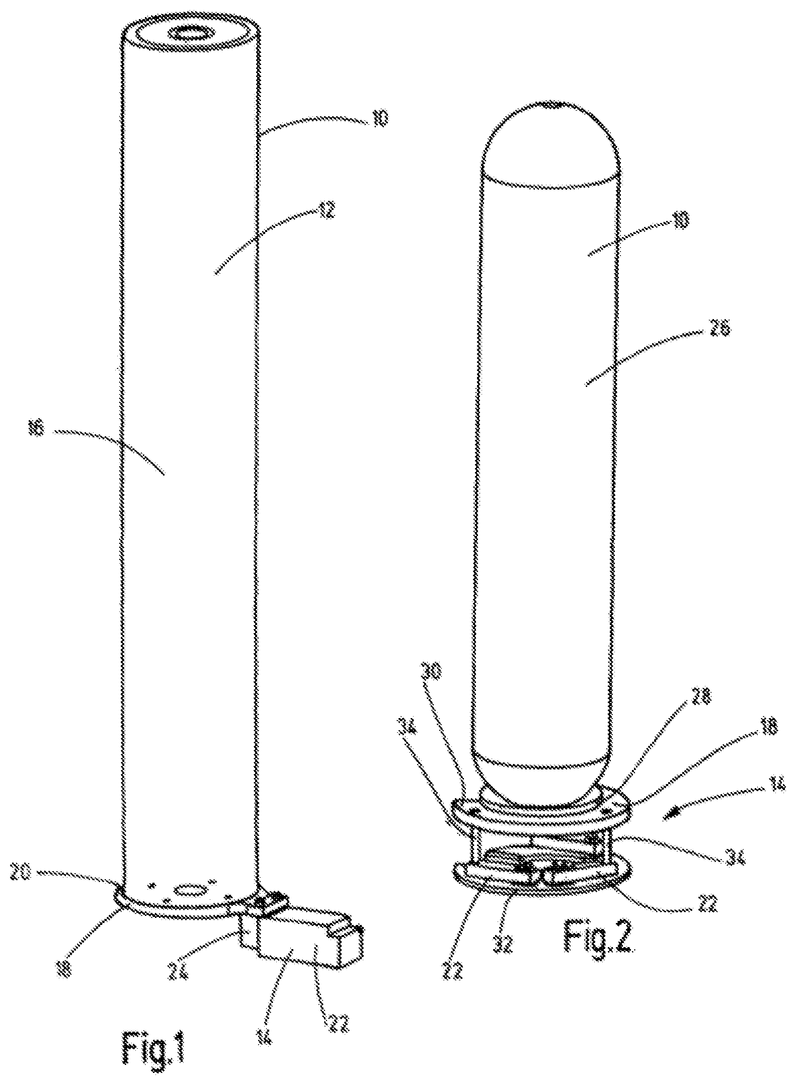
[0015] FIGS. 1 & 2 a perspective view of a piston accumulator or a bladder accumulator respectively including the associated weighing device;
[0016] FIGS. 3 & 4 once in perspective view and once in side elevation, the weighing device used for a bladder accumulator according to FIG. 2.
[0017] FIG. 1 depicts a device for determining the weight of a hydraulic accumulator 10 in form of a piston accumulator 12 in which the respective actual weight of the accumulator 10, 12 is ascertained by means of a weighing device 14 that engages with the hydraulic accumulator 10.
[0018] Such hydraulic accumulators are also called hydropneumatic accumulators or simply accumulators in the industry. The basic purpose of such hydraulic accumulators is to store a liquid, in particular in form of a hydraulic medium, under pressure inside the accumulator. When discharging the liquid inside the accumulator under the pressure of the pre-loaded gas into the hydraulic circuit of a hydraulic plant, the stored hydraulic energy can be released. To this end the respective hydraulic accumulator 10 is usually connected at its lower end through tubes (not shown in detail in FIGS. 1 and 2) to a hydraulic circuit or a hydraulic plant (not shown). The pressure of the liquid in the accumulator compresses a gas, usually in form of nitrogen, inside the hydraulic accumulator. After the volume discharge described above the accumulator gas expands and the pressure at the gas side is reduced. The gas stored inside the hydraulic accumulator and the hydraulic liquid are usually separated from each other by a separating element, which is preferably sealed against media leakage. Different separating elements are used depending on the design of the accumulator. A membrane accumulator uses a membrane as separating element; a bladder accumulator an elastomer bladder, a piston accumulator a piston and a bellows-type accumulator a metal bellows as separating member or separating element. The object of the separating member or separating element is to provide a separation between gas and liquid over a prolonged operating period of the respective hydraulic accumulator, wherein the loss of gas via the separating element into the liquid side of the accumulator can basically not be avoided.
[0019] The actual loss of gas essentially depends on the type of elastomer used for the separating membrane or the accumulator bladder, as well as the liquid used and the molecule size of the accumulator gas. Further influencing variables are predetermined by the choice of material and the thickness of the separating element, but the pressure differences during operation of the hydraulic accumulator between gas and liquid side as well as the number of load cycles in operation and the operating temperature of the hydraulic accumulator also play a significant role. Piston accumulators can generally lose gas from the gas side of the piston accumulator to its liquid side via the sealing system of the separating piston, which is guided along the inner circumference of the accumulator housing or pressure housing. The above-mentioned metal bellows accumulators, which are another kind of hydraulic accumulators, are on the other hand virtually gas-tight and have no permeation since the bellows-like metal membranes commonly used in them do not let any gas through, even at high temperatures; only in the instance of failure, that is, when the metal bellows rips, the accumulator also loses its ability to function, which also applies for failures of the separating element of membrane accumulators, bladder accumulators and piston accumulators.
[0020] The equations for the change of state of gases are used for sizing of the respective hydraulic accumulator, wherein nitrogen is commonly used as accumulator gas for hydraulic accumulators. When calculating and sizing accumulators the ideal change of state in gases is often used, whereas at very high pressures the respective real gas characteristics must be taken into consideration. Moreover, iterative computations are used under consideration of measured values for pressure change, temperature change and volume change.
[0021] As already explained, the functionality of the respective hydraulic accumulator is diminished if, due to losses, there is insufficient accumulator gas present in the gas side that is under a predeterminable pressure inside the accumulator 10. In this instance the liquid side of the hydraulic accumulator 10 necessarily takes up more liquid, which can easily be measured via the weighing device 14 for the hydraulic accumulator 10.
[0022] It is therefore possible, for example, to determine the empty weight by means of the weighing device 14 prior to taking the hydraulic accumulator 10 into service and, based upon reference values of known, functional accumulators it is possible to set the ideal liquid filling volume inside the hydraulic accumulator 10, the weight of which is detected by the weighing device 14. It is therefore known very accurately what the weight of a hydraulic accumulator 10 of a certain type and size in service should be to be operational. In the instance that the gas volume in the gas side decreases unintentionally during operation of the accumulator, the volume of the liquid in the liquid side increases correspondingly, depending on the operating cycle, and the resulting increase in mass or weight is registered by the weighing device 14. As soon as any predeterminable limit values are exceeded, the hydraulic accumulator 10 is recognized as being diminished in functionality or as inoperative with the result that the gas in the gas side is replenished at a predeterminable pressure, or it is replaced by a new accumulator.
[0023] Since the weighing device 14 is permanently attached to the hydraulic accumulator 10 and takes measurements continuously, it is possible to register trends via an evaluation and diagnosis unit (not shown in detail) and so determine for how long the accumulator may be functionally reliable. If the respective separating element fails, in this instance in form of a separating piston for the piston accumulator 12, the weighing device 14 detects this immediately since the entire hydraulic accumulator 10 fills up rapidly with liquid, wherein the rapidly rising liquid inrush is interpreted by the weighing device 14 together with the connected electronic evaluation unit as a failure of the hydraulic accumulator 10, which makes it particularly sensible to use such weighing devices 14 for those hydraulic accumulators 10 in machine components that are used, for example, in the power generation sector, if they are to ensure their reliability in the instance of failure by providing their function also in a breakdown situation.
[0024] By determining the state of the liquid and gas volumes through the weighing device 14, it is indirectly also possible to establish the piston position inside the accumulator housing of the piston accumulator 12, which in turn gives an indication regarding the desired unrestricted movement of the piston as separating element inside the accumulator housing 16.
[0025] The tube connections (not shown) of the hydraulic plant to which the hydraulic accumulators 10 with their liquid side are commonly connected at their bottom end have only a very indirect negative effect on the weight measurement by means of the weighing device 14 since the tubing is necessarily flexible and their influence on the weight can be compensated for by the electronic evaluation unit to which the weighing device 14 is connected. Erroneous measurements due to respective operating conditions of the hydraulic accumulator 10 are therefore excluded.
[0026] According to the representation in FIG. 1 the weighing device 14 is provided with a circular seat 18, which tightly encloses the bottom end 20 of the housing 16 of the hydraulic accumulator 10 so that the pressure vessel of the hydraulic accumulator 10 can be placed with its bottom end onto the seat 18 and is retained there. The seat 18 therefore supports the piston accumulator 12 in the manner of a weighing pan. The seat 18 is part of the weighing device 14, and the associated measuring facility comprises a load cell 22 with a bending beam 24 and at least one strain gauge (not shown) that is attached thereto. Load cells 22 of this kind are also called platform load cells in the industry. They may, for example, be purchased under the trading name PW12C . . . from the German company Hottinger Baldwin Messtechnik GmbH. The respective load cell 22 may also be designed as a double bending beam made from a metallic material, such as aluminum, with a preferably rectangular cross-section. Moreover, said measuring facility may also be connected to a signal amplifier of the electronic evaluation unit in order to visualize the measuring results. A suitable signal amplifier, for example DAD141.1, may be purchased from the company Soemer.
[0027] The annular seat 18 consists of a solid metal ring, which makes it possible for the tube connections (not shown) at the liquid side of the piston accumulator 12 to pass through the ring. According to the representation in FIG. 1, moreover, the respective collar in form of the seat 18 is, together with the associated components for mounting the piston accumulator 12, mounted to the seat 18 at the upper end of the respective load cell 22.
[0028] A weight measurement for a bladder accumulator 26 of a commonly used design is depicted in the embodiment according to FIG. 2. Through consideration of reference values for comparable bladder accumulators, and preferably based upon the determination of the weight when empty by means of the weighing device 14, it is now for the first time possible for a bladder accumulator 26 to ascertain a value for the fill level of the accumulator on the gas side in order to obtain an indication concerning the functionality and functional reliability of the bladder accumulator 26.
[0029] To this end the bladder accumulator 26 is inserted with its bottom end into a support ring 28, which is part of the already described seat 18. As is shown in particular in FIG. 3, the depicted support ring 28 is closed and is disposed at the upper side onto a slotted attachment ring 30, which is also part of the seat 18 and thus part of the weighing device 14. An equipment ring 32, which has a slot that corresponds to the attachment ring 30, extends coaxial to the support ring 28 and the attachment ring 30 below both said rings. The equipment ring 32 is also part of the weighing device 14 as a whole, and with it the weighing device 14 can be stood on a floor or other surface together with the bladder accumulator 26. Three load cells 22 are disposed and firmly attached on the upper annular ring surface of the equipment ring 32, wherein said load cells 22 carry at their top side a sensing column 34 each, which engage with their free upper end with the underside of the attachment ring 30.
[0030] The load cell 22 according to the embodiment in FIGS. 2 to 4 may be purchased under the product name K2A at the German company Wagetechnik Kohn GmbH. Said load cell K2A is part of the series of so-called double bending beam load cells that have an aluminum housing of a rectangular cross-section. The above-mentioned strain gauges are disposed on the upper and lower side. To this extent the sensing columns 34 are in operative connection with the upper strain gauge DMS of the load cell K2A.
[0031] Thus, with the combination of components depicted in FIGS. 3 and 4 a weighing device 14 has been provided as a measuring facility, which permits the acquisition of measurements concerning weight or mass respectively at any stage of fill level of hydraulic accumulators 10, such as, for example, the bladder accumulator 26 shown in FIG. 2. The load cells 22 described above have proven to be particularly suitable so that conclusions may be drawn, indirectly via the weight measurement of the hydraulic accumulator 10, to its current gas charging state. This has no equivalent in the prior art.
* * * * *
D00000
D00001
D00002
XML
uspto.report is an independent third-party trademark research tool that is not affiliated, endorsed, or sponsored by the United States Patent and Trademark Office (USPTO) or any other governmental organization. The information provided by uspto.report is based on publicly available data at the time of writing and is intended for informational purposes only.
While we strive to provide accurate and up-to-date information, we do not guarantee the accuracy, completeness, reliability, or suitability of the information displayed on this site. The use of this site is at your own risk. Any reliance you place on such information is therefore strictly at your own risk.
All official trademark data, including owner information, should be verified by visiting the official USPTO website at www.uspto.gov. This site is not intended to replace professional legal advice and should not be used as a substitute for consulting with a legal professional who is knowledgeable about trademark law.