Laser Level
ZHUANG; Zhiwei ; et al.
U.S. patent application number 16/710417 was filed with the patent office on 2020-06-11 for laser level. This patent application is currently assigned to Zhejiang Rongsheng Tools Co., Ltd. The applicant listed for this patent is Zhejiang Rongsheng Tools Co., Ltd. Invention is credited to Jianrong QIAN, Zhiwei ZHUANG.
| Application Number | 20200182616 16/710417 |
| Document ID | / |
| Family ID | 68013959 |
| Filed Date | 2020-06-11 |

| United States Patent Application | 20200182616 |
| Kind Code | A1 |
| ZHUANG; Zhiwei ; et al. | June 11, 2020 |
LASER LEVEL
Abstract
A laser level is provided. The laser level has a housing and a laser inside the housing. The laser level also has a laser fixing plate and a front cover plate. The laser is disposed in a mounting slot of the laser fixing plate. A sliding block is disposed in a space formed between the laser fixing plate and the front cover plate. A minus-shaped laser beam splitter and a cross-shaped laser beam splitter are disposed on the sliding block in a vertical direction. Both sides of the sliding block are further respectively provided with a sliding block pusher disposed in a way of passing through two sides of the housing. The sliding block pushers can move the sliding block in the vertical direction. The laser level can achieve positional exchange between the to minus-shaped laser beam splitter and the cross-shaped laser beam splitter.
| Inventors: | ZHUANG; Zhiwei; (Zhejiang, CN) ; QIAN; Jianrong; (Zhejiang, CN) | ||||||||||
| Applicant: |
|
||||||||||
|---|---|---|---|---|---|---|---|---|---|---|---|
| Assignee: | Zhejiang Rongsheng Tools Co.,
Ltd Zhejiang CN |
||||||||||
| Family ID: | 68013959 | ||||||||||
| Appl. No.: | 16/710417 | ||||||||||
| Filed: | December 11, 2019 |
| Current U.S. Class: | 1/1 |
| Current CPC Class: | G01C 15/008 20130101; G01C 15/004 20130101 |
| International Class: | G01C 15/00 20060101 G01C015/00 |
Foreign Application Data
| Date | Code | Application Number |
|---|---|---|
| Dec 11, 2018 | CN | 201822079333.4 |
Claims
1. A laser level comprising: a housing and a laser disposed inside the housing, and a laser fixing plate and a front cover plate disposed in sequence in the direction of the outgoing light of the laser, wherein the laser is disposed in a mounting slot of the laser fixing plate, a sliding block is disposed in a space formed between the laser fixing plate and the front cover plate, and a minus-shaped laser beam splitter and a cross-shaped laser beam splitter are disposed on the sliding block in a vertical direction, and wherein both sides of the sliding block are further respectively provided with a sliding block pusher disposed in a way of passing through two sides of the housing, the sliding block pushers being configured to move the sliding block in the vertical direction to utilize the minus-shaped laser beam splitter and the cross-shaped laser beam splitter to convert the outgoing light of the laser.
2. The laser level according to claim 1, wherein the laser fixing plate is further provided with a positioning steel ball and a compression spring for positioning the sliding block.
3. The laser level according to claim 2, wherein the sliding block is sequentially provided in a vertical direction with a first positioning groove and a second positioning groove for accommodating the positioning steel ball.
4. The laser level according to claim 1, wherein a laser switch is further disposed at the top of the housing.
5. The laser level according to claim 1, wherein the top of the housing is further provided with a horizontal bubble seat and a turning bubble seat for positioning the laser level.
6. The laser level according to claim 5, wherein the top of the housing is further provided with a bubble lamp switch.
7. The laser level according to claim 1, wherein the bottom of the housing is further provided with a magnet for fixing the housing.
Description
[0001] This application claims the benefit of priority to Chinese Patent Application No. 201822079333.4 titled "LASER LEVEL", filed with the Chinese State Intellectual Property Office on Dec. 11, 2018, the entire disclosure of which is incorporated herein by reference for all purposes. No new matter has been introduced.
TECHNICAL FIELD
[0002] The application belongs to the technical field of measuring devices, and in particular relates to a laser level.
BACKGROUND
[0003] The laser level is a measurement tool that is often used in civil construction, decoration, and installation of items. Due to the limitations of its own profile and size, the laser levels manufactured both at home and abroad can only produce one laser horizontal point and one laser horizontal line. When it is necessary to measure or correct a measured object in the horizon direction, such a level cannot meet the requirements.
SUMMARY
[0004] The object of the application is to address at least one of the above defects and shortcomings, and it is realized through the following technical solutions.
[0005] A laser level is proposed by the application, which includes a housing and a laser disposed inside the housing, and further includes a laser fixing plate and a front cover plate disposed in sequence in the direction of the outgoing light of the laser, wherein the laser is disposed in a mounting slot of the laser fixing plate, a sliding block is disposed in a space formed between the laser fixing plate and the front cover plate, and a minus-shaped laser beam splitter and a cross-shaped laser beam splitter are disposed on the sliding block in a vertical direction; both sides of the sliding block are further respectively provided with a sliding block pusher disposed in a way of passing through two sides of the housing, the sliding block pushers being capable of moving the sliding block in the vertical direction, thereby utilizing the minus-shaped type laser beam splitter and the cross-shaped laser beam splitter to convert the outgoing light of the laser.
[0006] Further, in the laser level of the present application, the laser fixing plate is further provided with a positioning steel ball and a compression spring for positioning the sliding block.
[0007] to Further, in the laser level of the present application, the sliding block is sequentially provided in a vertical direction with a first positioning groove and a second positioning groove for accommodating the positioning steel ball.
[0008] Further, in the laser level of the present application, a laser switch is further disposed at the top of the housing.
[0009] Further, in the laser level of the present application, the top of the housing is further provided with a horizontal bubble seat and a turning bubble seat for positioning the laser level.
[0010] Further, in the laser level of the present application, the top of the housing is further provided with a bubble lamp switch.
[0011] Further, in the laser level of the present application, the bottom of the housing is further provided with a magnet for fixing the housing.
[0012] By using the laser level of the present application, the positional exchange between the minus-shaped laser beam splitter and the cross-shaped laser beam splitter can be effectively realized, so that the laser level not only can emit mutually perpendicular cross laser lines perpendicularly projected onto the object, but also emit a minus-shaped laser line that is projected in parallel onto the object.
BRIEF DESCRIPTION OF THE DRAWINGS
[0013] Various further advantages and benefits will become apparent to those skilled in the art upon reading a detailed description of the following preferred embodiments. The drawings are only provided for the purpose of illustrating the preferred embodiments, and are not intended to limit of the present application. Throughout the drawings, identical reference numerals are used to denote identical parts.
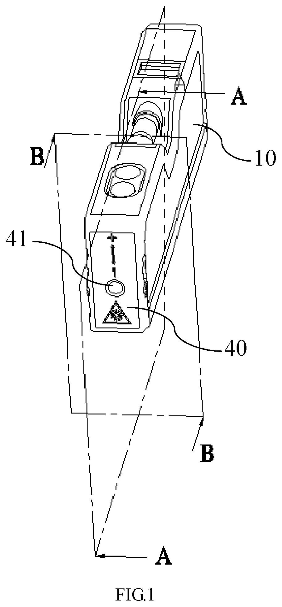
[0014] FIG. 1 is a schematic view of the overall structure of the present application;
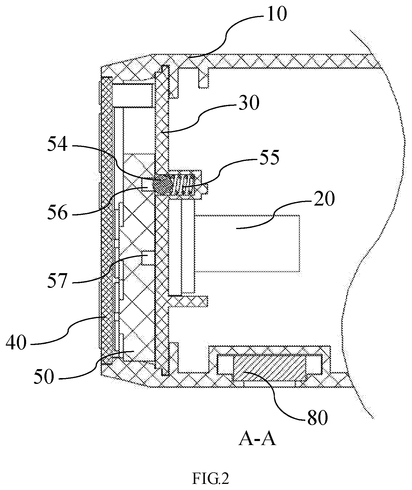
[0015] FIG. 2 is a schematic cross-sectional view taken along line A-A in the embodiment shown in FIG. 1; and
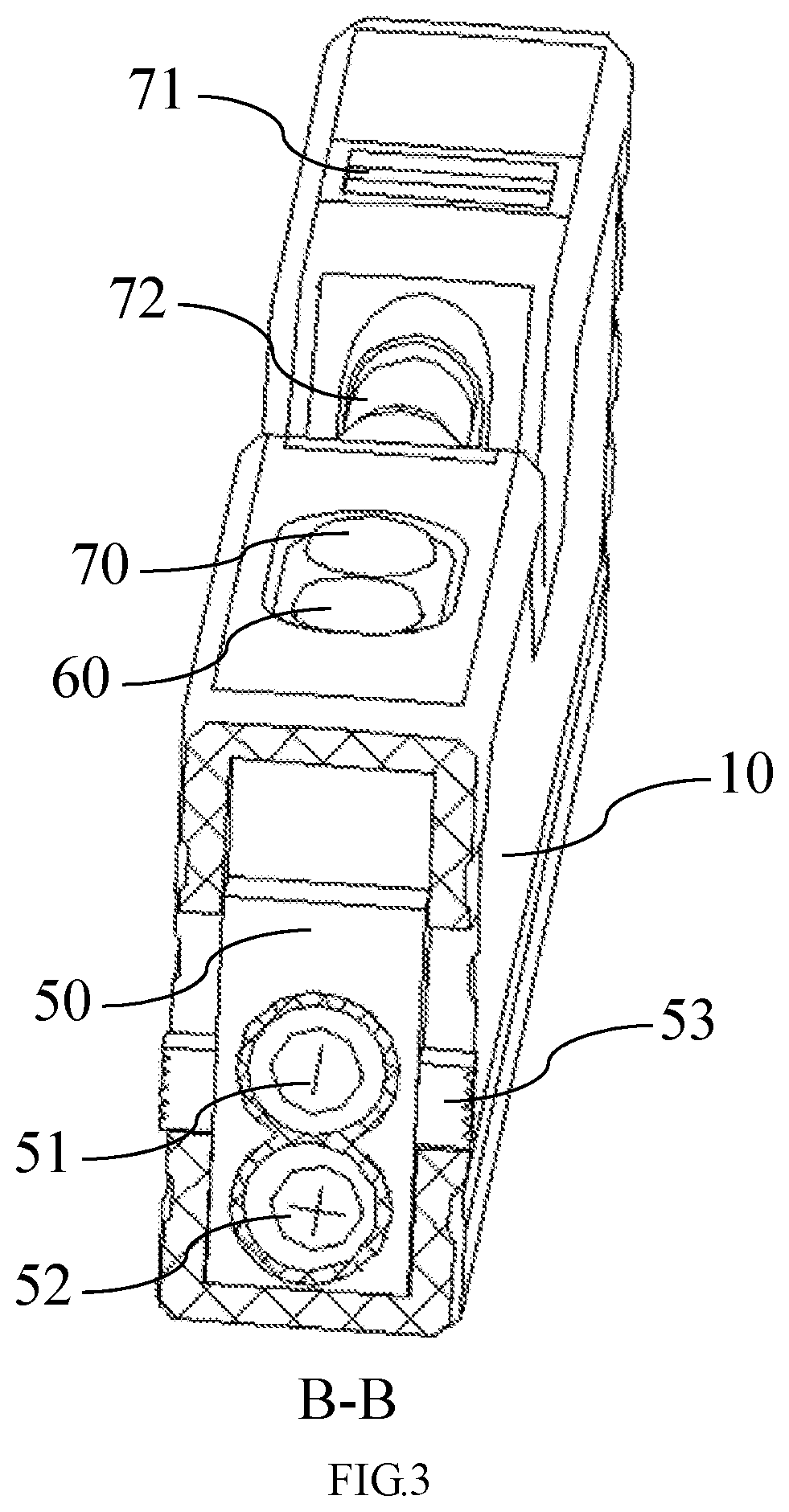
[0016] FIG. 3 is a schematic cross-sectional view taken along line B-B in the embodiment shown in FIG. 1.
LIST OF REFERENCE NUMERALS IN THE DRAWINGS
[0017] 10: housing; 20: laser; 30; laser fixing plate; 40: front cover plate; 41: light-through hole; 50: sliding block; 51: minus-shaped laser beam splitter; 52: cross-shaped laser beam splitter; 53: sliding block pusher; 54: positioning steel ball; 55: compression spring; 56: first positioning groove; 57: second positioning groove; 60: laser switch; 70: bubble lamp switch; 71: horizontal bubble seat; 72: turning bubble seat; 80: magnet.
DETAILED DESCRIPTION
[0018] Exemplary embodiments of the present disclosure will be described in greater detail below with reference to the accompanying drawings. While the exemplary embodiments of the present disclosure are shown in the drawings, it is understood that the present disclosure may be embodied in various forms and is not limited by the embodiments set forth herein. Rather, these embodiments are provided so that the present disclosure will be more fully understood, and the scope of the present disclosure can be fully conveyed to those skilled in the art.
[0019] It is to be understood that terms are used herein for the purpose of describing particular exemplary embodiments and are not intended to be limiting. The singular forms "a", "one" and "the" may also refer to plural forms, unless explicitly specified otherwise in the context. The terms "comprise", "contain", "comprising" and "have" are inclusive, and therefore indicate the existence of the recited features, steps, operations, elements and/or components, without precluding the existence or addition of one or more other features, steps, operations, elements, components and/or a combination thereof. The method steps, processes, and operations described herein are not to be construed as necessarily requiring that they are executed in the particular sequence as described or illustrated herein, unless the sequence is explicitly specified. It should also be understood that additional or alternative steps may be used.
[0020] Although the terms "first", "second", "third", etc. may be used to describe a plurality of elements, components, regions, layers and/or sections, these elements, components, regions, layers and/or sections should not be limited by these terms. These terms may be only used to distinguish one element, component, region, layer or section from another region, layer or section. Terms such as "first", "second" and other numerical terms when used in the present disclosure do not imply the sequence or order, unless explicitly specified otherwise in the context. Thus, the first element, component, region, layer or section may be referred to as the second element, component, region, layer or section without departing from the teachings of the exemplary embodiments.
[0021] For convenience of description, terms indicating spatial relative relationship may be used herein to describe the relationship of one element or feature as shown in the drawings with respect to another element or feature, such as "internal", "external", "inside", "outside", "beneath", "below", "on top of", "above", etc. Such terms indicating spatial relative relationship are intended to encompass different orientations of devices in use or in operation in addition to the orientation depicted in the drawings. For example, if the device in the drawings is turned over, the element described as "below another element or feature " or "beneath another element or feature" would then be oriented "above another element or feature" or "on top of another element or feature". Thus, the exemplary term "below" can encompass both orientations of "above" and "below". The device can be otherwise oriented (rotated by 90 degrees or oriented in other directions) and the spatial relative relationship descriptors used in the context are interpreted accordingly.
[0022] FIG. 1 is a schematic view of the overall structure of the present application; FIG. 2 is a schematic cross-sectional view taken along line A-A in the embodiment shown in FIG. 1; and FIG. 3 is a schematic cross-sectional view taken along line B-B in the embodiment shown in FIG. 1. As shown, the laser level according to the embodiment includes a housing 10 and a laser 20 disposed inside the housing 10, and further includes a laser fixing plate 30 and a front cover plate 40 disposed in sequence in the direction of the outgoing light of the laser 20, wherein the laser 20 is disposed in a mounting slot of the laser fixing plate 30, a sliding block 50 is disposed in a space formed between the laser fixing plate 30 and the front cover plate 40, and a minus-shaped laser beam splitter 51 and a cross-shaped laser beam splitter 52 are disposed on the sliding block 50 in a vertical direction; both sides of the sliding block 50 are further respectively provided with a sliding block pusher 53 disposed in a way of passing through two sides of the housing 10, the sliding block pushers 53 being capable of moving the sliding block 50 in the vertical direction, thereby utilizing the minus-shaped laser beam splitter 51 and the cross-shaped laser beam splitter 52 to convert the outgoing light of the laser 20.
[0023] In the embodiment, the minus-shaped laser beam splitter 51 and the cross-shaped laser beam splitter 52 are disposed on the sliding block 50, and by moving the sliding block pushers 53, the sliding block 50 is moved in the vertical direction so that the minus-shaped laser beam splitter 51 and the cross-shaped laser beam splitter 52 are utilized to convert the outgoing light of the laser 20. Meanwhile, the front cover plate 40 is disposed at the front end of the sliding block 50, and the front cover plate 40 is provided with a light-through hole 41 coaxially arranged with the laser 20. The front cover plate 40 can effectively protect the minus-shaped laser beam splitter 51 and the cross-shaped laser beam splitter 52 in the sliding block 50, and the arrangement of the sliding block pushers 53 enable a more convenient and swift switch of the positions of the minus-shaped laser beam splitter 51 and the cross-shaped laser beam splitter 52.
[0024] Further, in order to position the converted positions of the minus-shaped laser beam splitter 51 and the cross-shaped laser beam splitter 52, the laser fixing plate 30 is also provided with a positioning steel ball 54 and a compression spring 55 for positioning the sliding block 50. Correspondingly, the sliding block 50 is sequentially provided in a vertical direction with a first positioning groove 56 and a second positioning groove 57 for accommodating the positioning steel ball 54.
[0025] As shown in FIG. 2, when the first positioning groove 56 mates with the positioning steel ball 54, the positioning steel ball 54 is captured inside the first positioning groove 56 so that the position of the sliding block 50 is fixed. At this point, the minus-shaped laser beam splitter 51 is coaxially disposed with the laser 20, and the outgoing light of the laser 20 is therefore converted into a minus-shaped laser line that is projected in parallel onto the object. to When the second positioning groove 57 mates with the positioning steel ball 54, the positioning steel ball 54 is captured inside the second positioning groove 57 so that the position of the sliding block 50 is fixed. At this point, the cross-shaped laser beam splitter 52 is coaxially disposed with the laser 20, and the outgoing light of the laser 20 is therefore converted into mutually perpendicular cross laser lines perpendicularly projected onto the object.
[0026] As shown in FIG. 3, a laser switch 60 is further disposed at the top of the laser level of the embodiment. By pressing the laser switch 60, the laser 20 can be turned on so as to emit lights. The top of the housing 10 is further provided with a horizontal bubble seat 71 and a turning bubble seat 72 for positioning the laser level. The horizontal bubble seat 71 can be used for the alignment of the laser level in the horizontal direction, and the turning bubble seat 72 can be used for detecting a specific inclined angle of the laser level.
[0027] Further, in order to enable the use of the laser level of the embodiment in a poorly-illuminated environment, the top of the housing 50 is also provided with a bubble lamp switch 70. By pressing the bubble lamp switch 70, a bubble lamp inside the bubble seat can be turned on so as to effect illuminating and facilitate observation.
[0028] Further, in order to fix the laser level of the embodiment and prevent positional displacement thereof, the bottom of the housing 10 is also provided with a magnet 80 for fixing the housing 10. By fixing the laser level onto the surface of a fixing seat of a magnetic object, the magnet 80 and the fixing seat are attracted to each other, thus fixing the laser level.
[0029] By using the laser level of the present application, the positional exchange between the minus-shaped laser beam splitter and the cross-shaped laser beam splitter can be effectively realized, so that the laser level not only can emit mutually perpendicular cross laser lines perpendicularly projected onto the object, but also emit a minus-shaped laser line that is projected in parallel onto the object.
[0030] What have been described above are only specific preferred embodiments of the present application, and the scope of protection of the present application is not limited thereto. Variations and substitutes that can be readily conceived by any person skilled in the art within the technical scope disclosed by the present application are intended to be included within the to scope of protection of the present application. Therefore, the scope of protection of the present application should be determined by the scope of protection of the claims.
* * * * *
D00000
D00001
D00002
D00003
XML
uspto.report is an independent third-party trademark research tool that is not affiliated, endorsed, or sponsored by the United States Patent and Trademark Office (USPTO) or any other governmental organization. The information provided by uspto.report is based on publicly available data at the time of writing and is intended for informational purposes only.
While we strive to provide accurate and up-to-date information, we do not guarantee the accuracy, completeness, reliability, or suitability of the information displayed on this site. The use of this site is at your own risk. Any reliance you place on such information is therefore strictly at your own risk.
All official trademark data, including owner information, should be verified by visiting the official USPTO website at www.uspto.gov. This site is not intended to replace professional legal advice and should not be used as a substitute for consulting with a legal professional who is knowledgeable about trademark law.