Projectile Launcher With Inward Rotating Arms
Pauluhn; Adam Cuthbert ; et al.
U.S. patent application number 16/213659 was filed with the patent office on 2020-06-11 for projectile launcher with inward rotating arms. The applicant listed for this patent is Adam Cuthbert Beran Pauluhn. Invention is credited to Mark A. Beran, Adam Cuthbert Pauluhn.
| Application Number | 20200182582 16/213659 |
| Document ID | / |
| Family ID | 70972467 |
| Filed Date | 2020-06-11 |


| United States Patent Application | 20200182582 |
| Kind Code | A1 |
| Pauluhn; Adam Cuthbert ; et al. | June 11, 2020 |
PROJECTILE LAUNCHER WITH INWARD ROTATING ARMS
Abstract
A projectile launcher with a stationary element extending outwardly from a body and a pivotal element attached so as to extend forward, the pivotal element having a cocked position directed toward the body and a released position directed in the forward direction and a second stationary element and pivotal element similarly mounted but extending outwardly from the body in an opposite direction. A bowstring extending between the two pivotal elements and movable between a cocked and a released position. A latch movable between a closed position, retaining the bowstring in the cocked position, and an open position, releasing the bowstring. A tubular torsion bar coupled to the pivotal elements and movable between energy storage and releasing configurations. A delivery system coupling the torsion bar to the pivotal elements and transferring energy to and from the torsion bar when the bowstring is moved between the cocked and released positions.
| Inventors: | Pauluhn; Adam Cuthbert; (Niwot, CO) ; Beran; Mark A.; (Niwot, CO) | ||||||||||
| Applicant: |
|
||||||||||
|---|---|---|---|---|---|---|---|---|---|---|---|
| Family ID: | 70972467 | ||||||||||
| Appl. No.: | 16/213659 | ||||||||||
| Filed: | December 7, 2018 |
| Current U.S. Class: | 1/1 |
| Current CPC Class: | F41B 5/123 20130101; F41B 5/12 20130101; F41B 5/0094 20130101 |
| International Class: | F41B 5/12 20060101 F41B005/12 |
Claims
1. A projectile launcher with inward rotating arms comprising: a body having a rearward end, and a forward end, with a forward end direction being directed general toward the forward end; a first rigid arm having a first rigid stationary element extending outwardly from the body defining a first outer end area and a first rigid pivotal element pivotally attached to the first outer end area of the first rigid stationary element so as to extend in the forward end direction and defining a first distal end, the first rigid pivotal element being pivotable between a cocked position directed generally toward the body and a released position directed generally in the forward direction; a second rigid arm having a second rigid stationary element extending outwardly from the body in a direction opposite the first rigid stationary element defining a second outer end area and a second rigid pivotal element pivotally attached to the second outer end area of the second rigid stationary element so as to extend in the forward end direction and defining a second distal end, the second rigid pivotal element being pivotable between a cocked position directed generally toward the body and a released position directed generally in the forward direction; a bowstring extending between the distal ends of the first and second rigid pivotal arm elements and movable between a cocked position and a released position, movement of the bowstring from the released position to the cocked position rotates or pivots the first rigid pivotal element and the second rigid pivotal element from the released position to the cocked position; a latch mechanism movable between a closed position, retaining the bowstring in the cocked position, and an open position, releasing the bowstring to allow movement to the released position; at least one tubular torsion bar coupled to the pair of rigid arms, the at least one tubular torsion bar movable between a mechanical energy storage configuration and a mechanical energy releasing configuration; and a mechanical energy delivery system coupling the at least one tubular torsion bar to the first and second rigid pivotal elements, the mechanical energy delivery system transferring mechanical energy in the form of rotary movement of the first and second rigid pivotal elements to the at least one tubular torsion bar when the bowstring is moved from the released position to the cocked position, and transferring mechanical energy from the at least one tubular torsion bar to the first and second rigid pivotal elements to move the first and second rigid pivotal elements from the cocked position to the released position and the bowstring from the cocked position to the released position; and wherein the at least one tubular torsion bar includes an inner tube and an axially aligned outer tube and the mechanical energy delivery system includes a free end of the inner tube terminated with a first coaxially mounted pulley and a free end of the outer tube terminated with a second coaxially mounted pulley, the first and second coaxially mounted pulleys forming a portion of the mechanical energy delivery system.
2. (canceled)
3. A projectile launcher with inward rotating arms as claimed in claim 1 wherein the mechanical energy delivery system further includes a first pulley arrangement mounted at the first outer end area of the first rigid stationary element for rotation with rotation of the first rigid pivotal element and a second pulley arrangement mounted at the second outer end area of the second rigid stationary element for rotation with rotation of the second rigid pivotal element.
4. A projectile launcher with inward rotating arms as claimed in claim 3 wherein the mechanical energy delivery system further includes one or more strings wound at least partially around the first coaxially mounted pulley, the first pulley arrangement mounted at the first outer end area, the second pulley arrangement mounted at the second outer end area, and the second coaxially mounted pulley.
5. A projectile launcher with inward rotating arms as claimed in claim 3 wherein the first rigid pivotal element is pivotally attached to the first rigid stationary element by a first axle and the first pulley arrangement includes a first pair of spaced apart pulleys attached to the first axle for rotation therewith and the second rigid pivotal element is pivotally attached to the second rigid stationary element by a second axle and the second pulley arrangement includes a second pair of spaced apart pulleys attached to the second axle for rotation therewith.
6. A projectile launcher with inward rotating arms comprising: a body having a rearward end, and a forward end, with a forward end direction being directed general toward the forward end; a first rigid arm having a first rigid stationary element extending outwardly from the body defining a first outer end area and a first rigid pivotal element pivotally attached to the first outer end area of the first rigid stationary element so as to extend in the forward end direction and defining a first distal end, the first rigid pivotal element being pivotable between a cocked position directed generally toward the body and a released position directed generally in the forward direction; a second rigid arm having a second rigid stationary element extending outwardly from the body in a direction opposite the first rigid stationary element defining a second outer end area and a second rigid pivotal element pivotally attached to the second outer end area of the second rigid stationary element so as to extend in the forward end direction and defining a second distal end, the second rigid pivotal element being pivotable between a cocked position directed generally toward the body and a released position directed generally in the forward direction; a bowstring extending between the distal ends of the first and second rigid pivotal arm elements and movable between a cocked position and a released position, movement of the bowstring from the released position to the cocked position rotates or pivots the first rigid pivotal element and the second rigid pivotal element from the released position to the cocked position; a latch mechanism movable between a closed position, retaining the bowstring in the cocked position, and an open position, releasing the bowstring to allow movement to the released position; at least one tubular torsion bar coupled to the pair of rigid arms, the at least one tubular torsion bar movable between a mechanical energy storage configuration and a mechanical energy releasing configuration; a mechanical energy delivery system coupling the at least one tubular torsion bar to the first and second rigid pivotal elements, the mechanical energy delivery system transferring mechanical energy in the form of rotary movement of the first and second rigid pivotal elements to the at least one tubular torsion bar when the bowstring is moved from the released position to the cocked position, and transferring mechanical energy from the at least one tubular torsion bar to the first and second rigid pivotal elements to move the first and second rigid pivotal elements from the cocked position to the released position and the bowstring from the cocked position to the released position; and wherein the at least one tubular torsion bar includes two tubular torsion bars each having an inner tube and an axially aligned outer tube and the mechanical energy delivery system includes a free end of one of the inner tube and the outer tube of each of the two tubular torsion bars terminated with coaxially mounted pulleys.
7. A projectile launcher with inward rotating arms as claimed in claim 1 wherein the first and second rigid stationary elements are formed as a single unit.
8. A projectile launcher with inward rotating arms comprising: a body having a rearward end, and a forward end, with a forward end direction being directed general toward the forward end; a first rigid arm having a first rigid stationary element extending outwardly from the body defining a first outer end area and a first rigid pivotal element pivotally attached to the first outer end area of the first rigid stationary element so as to extend in the forward end direction and defining a first distal end, the first rigid pivotal element being pivotable between a cocked position directed generally toward the body and a released position directed generally in the forward direction; a second rigid arm having a second rigid stationary element extending outwardly from the body in a direction opposite the first rigid stationary element defining a second outer end area and a second rigid pivotal element pivotally attached to the second outer end area of the second rigid stationary element so as to extend in the forward end direction and defining a second distal end, the second rigid pivotal element being pivotable between a cocked position directed generally toward the body and a released position directed generally in the forward direction; a bowstring extending between the distal ends of the first and second rigid pivotal arm elements and movable between a cocked position and a released position, movement of the bowstring from the released position to the cocked position rotates or pivots the first rigid pivotal element and the second rigid pivotal element from the released position to the cocked position; a latch mechanism movable between a closed position, retaining the bowstring in the cocked position, and an open position, releasing the bowstring to allow movement to the released position; a mechanical energy delivery system including a tubular torsion bar including an inner tube and an axially aligned outer tube, a free end of the inner tube terminated with a first coaxially mounted pulley and a free end of the outer tube terminated with a second coaxially mounted pulley, the tubular torsion bar movable between a mechanical energy storage configuration and a mechanical energy releasing configuration; and the mechanical energy delivery system further including a first pulley arrangement mounted at the first outer end area of the first rigid stationary element for rotation with rotation of the first rigid pivotal element and a second pulley arrangement mounted at the second outer end area of the second rigid stationary element for rotation with rotation of the second rigid pivotal element, and one or more strings wound at least partially around the first coaxially mounted pulley, the first pulley arrangement mounted at the first outer end area, the second pulley arrangement mounted at the second outer end area, and the second coaxially mounted pulley for opposite rotation of the first and second coaxially mounted pulleys; the mechanical energy delivery system transferring mechanical energy in the form of rotary movement of the first and second rigid pivotal elements to opposite rotation of the first and second coaxially mounted pulleys when the bowstring is moved from the released position to the cocked position, and transferring mechanical energy from the tubular torsion bar to the first and second rigid pivotal elements to move the first and second rigid pivotal elements from the cocked position to the released position and the bowstring from the cocked position to the released position.
9. A projectile launcher with inward rotating arms as claimed in claim 8 wherein the first and second rigid stationary elements are formed as a single unit.
10. A projectile launcher with inward rotating arms as claimed in claim 8 wherein the first rigid pivotal element is pivotally attached to the first rigid stationary element by a first axle and the first pulley arrangement includes a first pair of spaced apart pulleys attached to the first axle for rotation therewith and the second rigid pivotal element is pivotally attached to the second rigid stationary element by a second axle and the second pulley arrangement includes a second pair of spaced apart pulleys attached to the second axle for rotation therewith.
11. A projectile launcher with inward rotating arms comprising: a body having a rearward end, and a forward end, with a forward end direction being directed general toward the forward end; a first rigid arm having a first rigid stationary element extending outwardly from the body defining a first outer end area and a first rigid pivotal element pivotally attached to the first outer end area of the first rigid stationary element so as to extend in the forward end direction and defining a first distal end, the first rigid pivotal element being pivotable between a cocked position directed generally toward the body and a released position directed generally in the forward direction; a second rigid arm having a second rigid stationary element extending outwardly from the body in a direction opposite the first rigid stationary element defining a second outer end area and a second rigid pivotal element pivotally attached to the second outer end area of the second rigid stationary element so as to extend in the forward end direction and defining a second distal end, the second rigid pivotal element being pivotable between a cocked position directed generally toward the body and a released position directed generally in the forward direction; a bowstring extending between the distal ends of the first and second rigid pivotal arm elements and movable between a cocked position and a released position, movement of the bowstring from the released position to the cocked position rotates or pivots the first rigid pivotal element and the second rigid pivotal element from the released position to the cocked position; a latch mechanism movable between a closed position, retaining the bowstring in the cocked position, and an open position, releasing the bowstring to allow movement to the released position; a mechanical energy delivery system including a plurality of tubular torsion bars each including an inner tube and an axially aligned outer tube, each of the plurality of tubular torsion bars including a free end of one of the inner and outer tubes terminated with a coaxially mounted pulley, each of the plurality of tubular torsion bars movable between a mechanical energy storage configuration and a mechanical energy releasing configuration; and the mechanical energy delivery system further including a first pulley arrangement mounted at the first outer end area of the first rigid stationary element for rotation with rotation of the first rigid pivotal element and a second pulley arrangement mounted at the second outer end area of the second rigid stationary element for rotation with rotation of the second rigid pivotal element, and one or more strings wound at least partially around the coaxially mounted pulleys, the first pulley arrangement mounted at the first outer end area, and the second pulley arrangement mounted at the second outer end area; the mechanical energy delivery system transferring mechanical energy in the form of rotary movement of the first and second rigid pivotal elements to rotation of the coaxially mounted pulleys when the bowstring is moved from the released position to the cocked position, and transferring mechanical energy from the plurality of tubular torsion bars to the first and second rigid pivotal elements to move the first and second rigid pivotal elements from the cocked position to the released position and the bowstring from the cocked position to the released position.
12. A projectile launcher with inward rotating arms as claimed in claim 11 wherein the first and second rigid stationary elements are formed as a single unit.
13. A projectile launcher with inward rotating arms as claimed in claim 11 wherein the first rigid pivotal element is pivotally attached to the first rigid stationary element by a first axle and the first pulley arrangement includes a first pair of spaced apart pulleys attached to the first axle for rotation therewith and the second rigid pivotal element is pivotally attached to the second rigid stationary element by a second axle and the second pulley arrangement includes a second pair of spaced apart pulleys attached to the second axle for rotation therewith.
Description
CROSS-REFERENCE TO RELATED APPLICATION
[0001] This application claims the benefit of U.S. Provisional Application No. 62/570,608, filed 10 Oct. 2017.
FIELD OF THE INVENTION
[0002] This invention relates to mechanisms for launching projectiles and more specifically to projectile mechanisms with inward rotating arms to generate larger stored mechanical energy.
BACKGROUND OF THE INVENTION
[0003] As explained in detail in U.S. Pat. No. 9,310,156, entitled "Projectile Launcher", issued Apr. 12, 2016, in the field of projectile launchers, there are three main categories, chemical energy devices (i.e. firearms), compressed air devices (i.e. air guns), and mechanical energy devices, (i.e. crossbows). Each have particular strengths and weaknesses. Mechanical energy devices, specifically crossbows, can provide great power with a large projectile. They are quiet to use with no flash, and are cost effective since the mechanical energy device can typically be reset. In traditional crossbows, the energy used to launch the projectile is stored in the flexing of the bow arms. The projectile launcher in the above cited patent incorporates one or more tubular torsion bars in which energy is stored by stressing components of the tubular torsion bars through rotation of bow arms and a pulley system. In this system, the amount of energy that can be stored in the tubular torsion bar or bars is determined by the amount of rotation of the pulleys which is determined by the movement (rotation) of the bow arms. Generally, the bow arms are limited to a pivotal or rotary movement of less than ninety degrees.
[0004] It would be highly advantageous, therefore, to remedy the foregoing and other deficiencies inherent in the prior art.
[0005] An object of the present invention is to provide a new and improved projectile launcher with inward rotating arms to produce greater power than the prior art.
[0006] Another object of the present invention is to provide a new and improved projectile launcher with inward rotating arms to produce increased energy storage capabilities.
SUMMARY OF THE INVENTION
[0007] Briefly, to achieve the desired objects and advantages of the instant invention provided is a projectile launcher with inward rotating arms. The projectile launcher includes a body having a rearward end, and a forward end, with a forward end direction being directed general toward the forward end. The launcher further includes a first rigid arm having a first rigid stationary element extending outwardly from the body defining a first outer end area and a first rigid pivotal element pivotally attached to the first outer end area of the first rigid stationary element so as to extend in the forward end direction and defining a first distal end. The first rigid pivotal element is pivotable between a cocked position directed generally toward the body and a released position directed generally in the forward direction. A second rigid arm has a second rigid stationary element extending outwardly from the body in a direction opposite the first rigid stationary element defining a second outer end area and a second rigid pivotal element pivotally attached to the second outer end area of the second rigid stationary element so as to extend in the forward end direction and defining a second distal end. The second rigid pivotal element is pivotable between a cocked position directed generally toward the body and a released position directed generally in the forward direction. The launcher further includes a bowstring extending between the distal ends of the first and second rigid pivotal arm elements and movable between a cocked position and a released position, movement of the bowstring from the released position to the cocked position rotates or pivots the first rigid pivotal element and the second rigid pivotal element from the released position to the cocked position. A latch mechanism is movable between a closed position, retaining the bowstring in the cocked position, and an open position, releasing the bowstring to allow movement to the released position. At least one tubular torsion bar is coupled to the pair of rigid arms, the at least one tubular torsion bar is movable between a mechanical energy storage configuration and a mechanical energy releasing configuration. A mechanical energy delivery system couples the at least one tubular torsion bar to the first and second rigid pivotal elements. The mechanical energy delivery system transfers mechanical energy in the form of rotary movement of the first and second rigid pivotal elements to the at least one tubular torsion bar when the bowstring is moved from the released position to the cocked position, and transfers mechanical energy from the at least one tubular torsion bar to the first and second rigid pivotal elements to move the first and second rigid pivotal elements from the cocked position to the released position and the bowstring from the cocked position to the released position.
[0008] A specific embodiment of a projectile launcher with inward rotating arms includes a body having a rearward end, and a forward end, with a forward end direction being directed general toward the forward end. A first rigid arm has a first rigid stationary element extending outwardly from the body defining a first outer end area and a first rigid pivotal element pivotally attached to the first outer end area of the first rigid stationary element so as to extend in the forward end direction and defining a first distal end. The first rigid pivotal element is pivotable between a cocked position directed generally toward the body and a released position directed generally in the forward direction. A second rigid arm has a second rigid stationary element extending outwardly from the body in a direction opposite the first rigid stationary element defining a second outer end area and a second rigid pivotal element pivotally attached to the second outer end area of the second rigid stationary element so as to extend in the forward end direction and defining a second distal end. The second rigid pivotal element is pivotable between a cocked position directed generally toward the body and a released position directed generally in the forward direction. A bowstring extends between the distal ends of the first and second rigid pivotal arm elements and is movable between a cocked position and a released position, movement of the bowstring from the released position to the cocked position rotates or pivots the first rigid pivotal element and the second rigid pivotal element from the released position to the cocked position. A latch mechanism is movable between a closed position, retaining the bowstring in the cocked position, and an open position, releasing the bowstring to allow movement to the released position. A mechanical energy delivery system includes a tubular torsion bar having an inner tube and an axially aligned outer tube, a free end of the inner tube terminated with a first coaxially mounted pulley and a free end of the outer tube terminated with a second coaxially mounted pulley. The tubular torsion bar is movable between a mechanical energy storage configuration and a mechanical energy releasing configuration. The mechanical energy delivery system further includes a first pulley arrangement mounted at the first outer end area of the first rigid stationary element for rotation with rotation of the first rigid pivotal element and a second pulley arrangement mounted at the second outer end area of the second rigid stationary element for rotation with rotation of the second rigid pivotal element, and one or more strings wound around the first coaxially mounted pulley, the first pulley arrangement mounted at the first outer end area, the second pulley arrangement mounted at the second outer end area, and the second coaxially mounted pulley for opposite rotation of the first and second coaxially mounted pulleys. The mechanical energy delivery system transfers mechanical energy in the form of rotary movement of the first and second rigid pivotal elements to opposite rotation of the first and second coaxially mounted pulleys when the bowstring is moved from the released position to the cocked position, and transferring mechanical energy from the tubular torsion bar to the first and second rigid pivotal elements to move the first and second rigid pivotal elements from the cocked position to the released position and the bowstring from the cocked position to the released position.
[0009] A specific embodiment of a projectile launcher with inward rotating arms includes a body having a rearward end, and a forward end, with a forward end direction being directed general toward the forward end. The specific embodiment further includes a first rigid arm having a first rigid stationary element extending outwardly from the body defining a first outer end area and a first rigid pivotal element pivotally attached to the first outer end area of the first rigid stationary element so as to extend in the forward end direction and defining a first distal end, the first rigid pivotal element being pivotable between a cocked position directed generally toward the body and a released position directed generally in the forward direction. A second rigid arm has a second rigid stationary element extending outwardly from the body in a direction opposite the first rigid stationary element defining a second outer end area and a second rigid pivotal element pivotally attached to the second outer end area of the second rigid stationary element so as to extend in the forward end direction and defining a second distal end. The second rigid pivotal element is pivotable between a cocked position directed generally toward the body and a released position directed generally in the forward direction. A bowstring extends between the distal ends of the first and second rigid pivotal arm elements and is movable between a cocked position and a released position, movement of the bowstring from the released position to the cocked position rotates or pivots the first rigid pivotal element and the second rigid pivotal element from the released position to the cocked position. A latch mechanism is movable between a closed position, retaining the bowstring in the cocked position, and an open position, releasing the bowstring to allow movement to the released position. A mechanical energy delivery system includes a plurality of tubular torsion bars each including an inner tube and an axially aligned outer tube, each of the plurality of tubular torsion bars including a free end of one of the inner and outer tubes terminated with a coaxially mounted pulley, each of the plurality of tubular torsion bars movable between a mechanical energy storage configuration and a mechanical energy releasing configuration. The mechanical energy delivery system further including a first pulley arrangement mounted at the first outer end area of the first rigid stationary element for rotation with rotation of the first rigid pivotal element and a second pulley arrangement mounted at the second outer end area of the second rigid stationary element for rotation with rotation of the second rigid pivotal element, and one or more strings wound around the coaxially mounted pulleys, the first pulley arrangement mounted at the first outer end area, and the second pulley arrangement mounted at the second outer end area. The mechanical energy delivery system transferring mechanical energy in the form of rotary movement of the first and second rigid pivotal elements to rotation of the coaxially mounted pulleys when the bowstring is moved from the released position to the cocked position, and transferring mechanical energy from the plurality of tubular torsion bars to the first and second rigid pivotal elements to move the first and second rigid pivotal elements from the cocked position to the released position and the bowstring from the cocked position to the released position.
BRIEF DESCRIPTION OF THE DRAWINGS
[0010] The foregoing and further and more specific objects and advantages of the invention will become readily apparent to those skilled in the art from the following detailed description of a preferred embodiment thereof, taken in conjunction with the drawings in which:
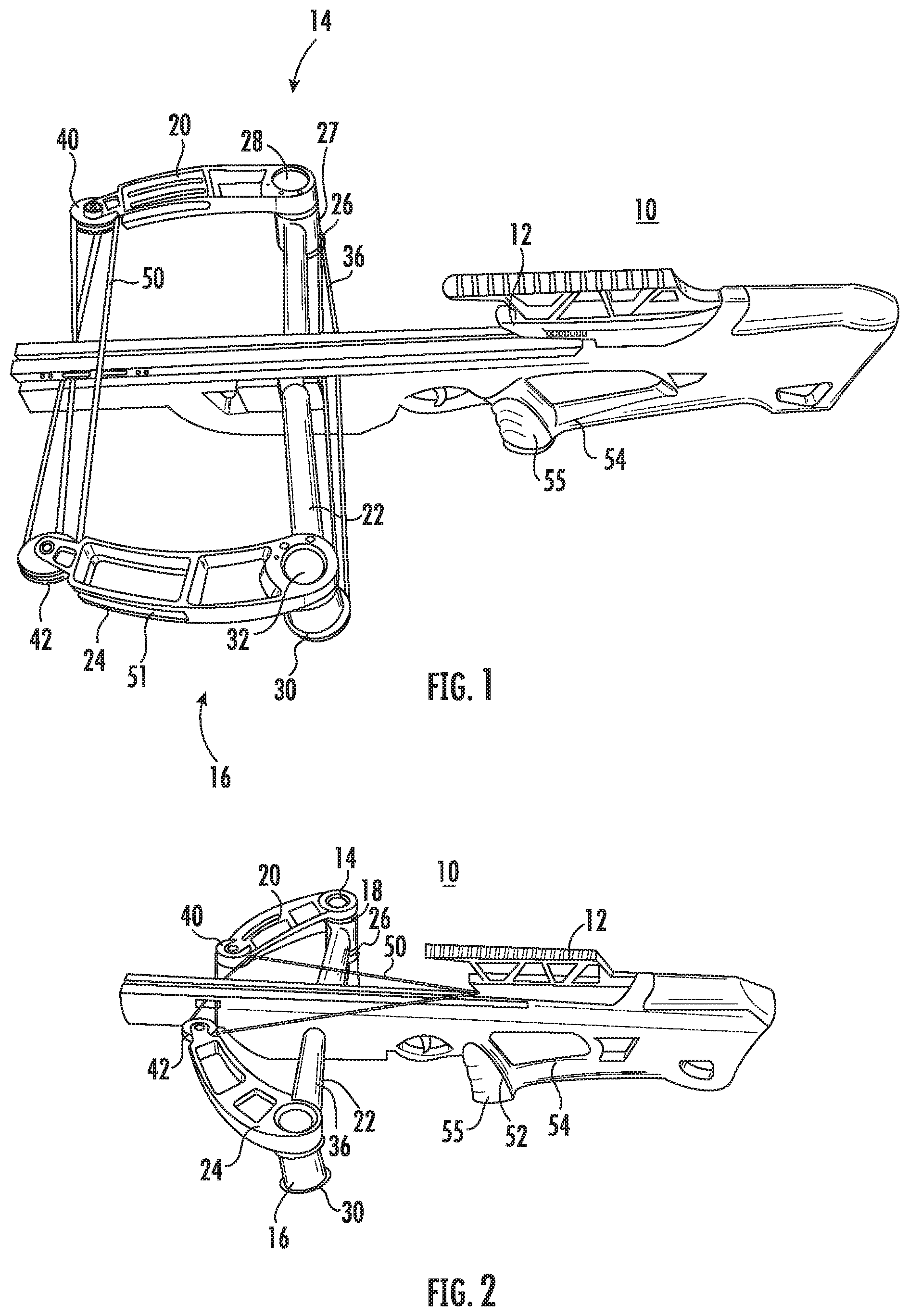
[0011] FIG. 1 is a perspective top view of a projectile launcher with inward swinging arms according to the present invention;
[0012] FIG. 2 is a perspective bottom view of the projectile launcher of FIG. 1;
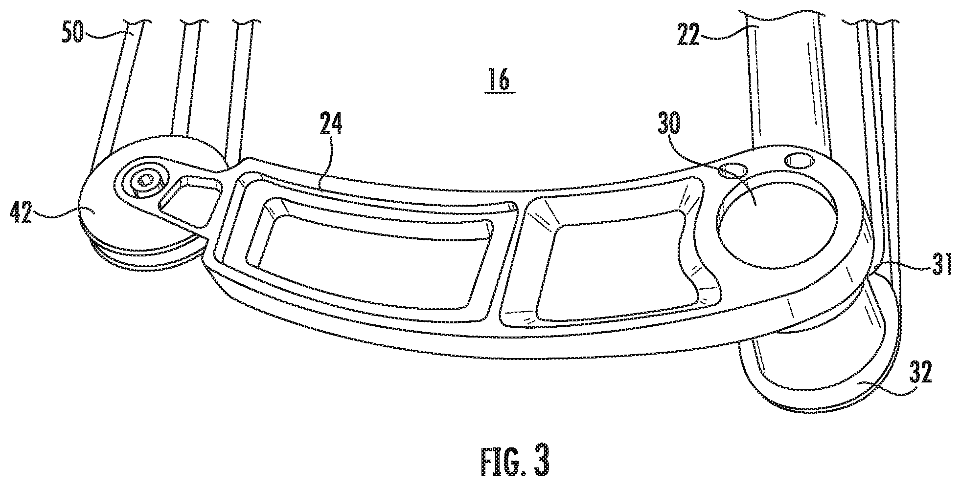
[0013] FIG. 3 is an enlarged perspective view of one end of the inward swinging arms mounting system;
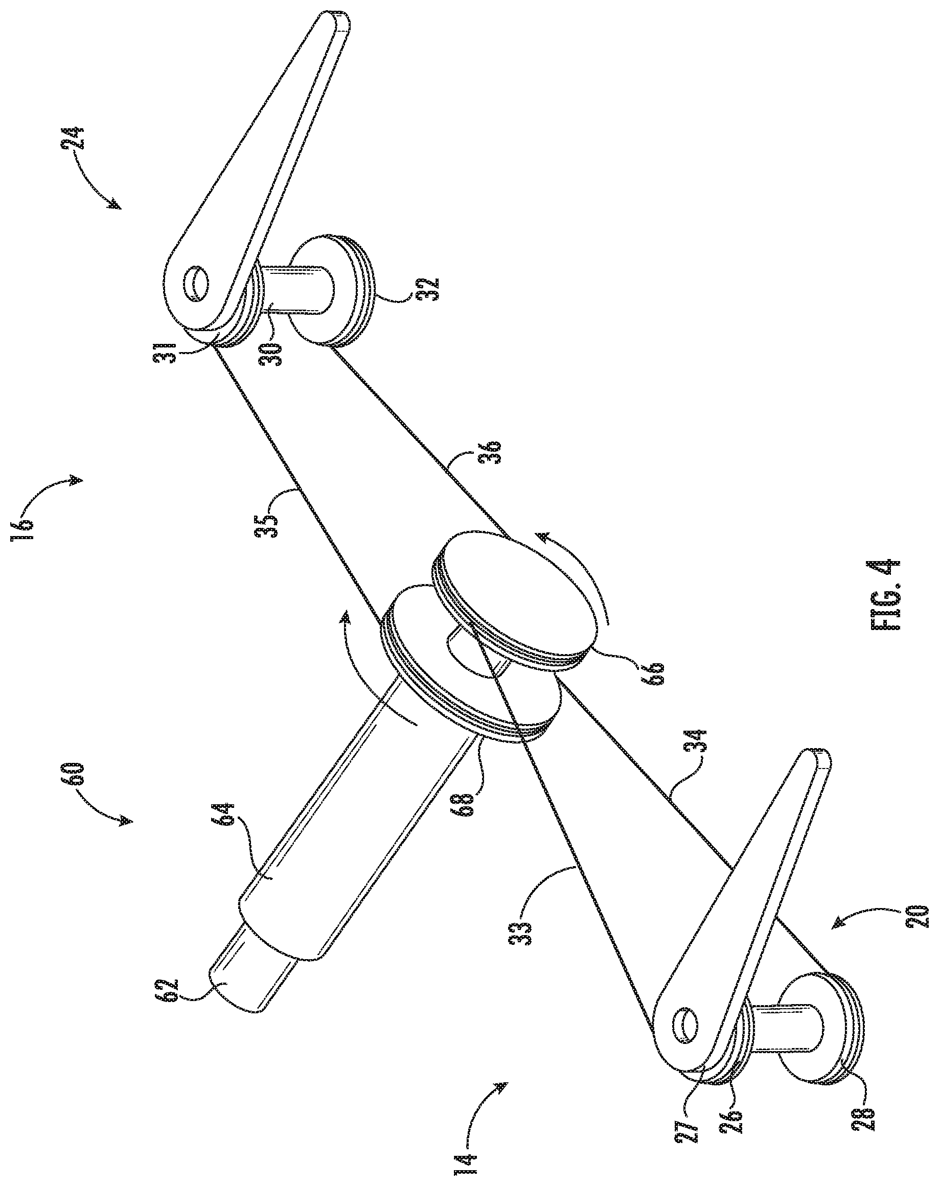
[0014] FIG. 4 is a simplified perspective view of the coupling between the energy storage and delivery system and the inward swinging arms of the present invention, in the unloaded spring (released) position;
[0015] FIG. 5 is a simplified perspective view of the coupling between the energy storage and delivery system and the inward swinging arms of the present invention, in the spring loaded (cocked) position; and
[0016] FIG. 6 is a perspective view of the energy storage and delivery system of the projectile launcher with multiple tubular torsion bars.
DETAILED DESCRIPTION OF A PREFERRED EMBODIMENT
[0017] Turning now to the drawings in which like reference characters indicate corresponding elements throughout the several views, attention is directed to FIGS. 1 and 2 which illustrate a projectile launcher generally designated 10. Projectile launcher 10 includes a body 12 having a rearward end terminating in a buttstock and a forward end. Body 12 receives, supports, and guides a projectile, preferably along a groove formed on a top surface thereof. Body 12 carries a pair of arms 14 and 16 extending outwardly in opposite directions. Arm 14 includes a rigid stationary element 18 extending outwardly in a right-hand direction, perpendicular to the body. A rigid pivotal arm element 20 is rotatably or pivotally attached at one end to the outer end of rigid stationary element 18 so as to extend in a generally (because of the preferred arcuate shape) forward direction and movable between a released position, generally parallel to body 12 in the embodiment, and a cocked position, generally perpendicular to body 12 in this embodiment. Arm 16 includes a rigid stationary element 22 extending outwardly in a left-hand direction, perpendicular to the body. A rigid pivotal arm element 24 is rotatably or pivotally attached at one end to the outer end of rigid stationary element 22 so as to extend in a generally (because of the preferred arcuate shape) forward direction and movable between a released position, generally parallel to body 12 in the embodiment, and a cocked position, generally perpendicular to body 12 in this embodiment. It should be understood that rigid stationary element 18 and rigid stationary element 22 could be provided as separate elements attached to body 12 or they could be provided as a single continuous element attached to body 12 so as to extend outwardly in opposite directions. In any case the outwardly projecting portions are considered components of the pair of arms 14 and 16.
[0018] Pivotal arm element 20 is rotatably attached to stationary element 18 by an axle 26 with an at least one pulley arrangement, which in this specific example includes a pulley 27 fixedly attached adjacent the upper end for rotation therewith and a pulley 28 fixedly attached to the lower end for rotation therewith. Thus, rotation of pivotal arm element 20 rotates pulleys 27 and 28 by way of axle 26. Similarly, pivotal arm element 24 is rotatably attached to stationary element 22 by an axle 30 with an at least one pulley arrangement which in this specific example includes a pulley 31 fixedly attached adjacent the upper end for rotation therewith and a pulley 32 fixedly attached to the lower end for rotation therewith. Pivotal arm element 24 is attached to stationary element 22 at an angle similar to pivotal arm element 20. Thus, rotation of pivotal arm element 24 rotates pulleys 31 and 32 by way of axle 30. Strings are wound around pulleys 27, 28, 31 and 32 and attached to elements of one or more tubular torsion bars mounted on body 12 to move pivotal arm elements 20 and 24 from the cocked position to the release position. Examples of this mounting arrangement are described in more detail below.
[0019] A pulley 40 is rotatably mounted at the distal or forward end of pivotal arm element 20 and a pulley 42 is rotatably mounted at the distal or forward end of pivotal arm element 24. A bow string 50 is wound around pulleys 40 and 42 with one section extending directly between the two for engagement with a latch mechanism 52. Bowstring 50 is movable between a cocked position (illustrated in FIG. 2) and a released position (illustrated in FIG. 1). In the cocked position, bowstring 50 is pulled rearwardly and retained by latch mechanism 52, concurrently moving pivotal arm elements 20 and 24 to the cocked position. Latch mechanism 52 is movable between an open and a closed position by a trigger assembly 54 coupled thereto. In the closed configuration, latch mechanism 52 retains bowstring 50 in the cocked position. In the open configuration, latch mechanism 52 disengages bowstring 50, releasing it to the released position, concurrently allowing one or more tubular torsion bars to move pivotal arm elements 20 and 24 to the released position. While not described in any detail, a cocking mechanism 55 is provided and can include substantially any conventional mechanism used in conventional crossbows for moving the bowstring rearwardly to the cocked position. These mechanisms can include levers, cranks, a user fingers and the like. In the present embodiment, a lever mechanism is illustrated. The specific winding or arrangement of bow string 50 is described in more detail below.
[0020] Referring additionally to FIG. 3, an enlarged view of a portion of arm 16 is illustrated. Since both arms 14 and 16 are identical, only the attachment of arm 16 is illustrated. As can be seen in more detail, pivotal arm element 24 is rotatably attached to stationary element 22 by an axle 30 which has a pulley 31 fixedly attached to the upper end for rotation therewith and a pulley 32 fixedly attached to the lower end for rotation therewith. Thus, rotation of pivotal arm element 24 rotates pulleys 31 and 32 by way of axle 30. Strings are wound around pulleys 31 and 32 and attached to elements of one or more tubular torsion bars mounted on body 12. Pulley 42 is rotatably mounted at the distal or forward end of pivotal arm element 24. A bow string 50 is wound around pulley 42 with one section extending directly between the pulleys 40 and 42 for engagement with a latch mechanism 52 on body 12. Turning now to FIG. 4, the coupling between the energy storage and delivery system of projectile launcher 10 and the inward swinging arms 14 and 16 in the unloaded spring (released) position (some spring tension can remain in the unloaded spring position), is illustrated in a simplified view. In FIG. 4, only the moving components are illustrated in their relative positions to simplify understanding of the operation. In this specific example, the energy storage and delivery system includes a single tubular torsion bar 60. Torsion bar 60 includes an inner tube 62 and an axially aligned outer tube 64 fixedly joined at a distal end (not shown) by a mounting structure or the like and the outer ends are free. Torsional or spring energy is stored in torsion bar 60 by relative rotation between inner tube 62 and outer tube 64 with the amount of relative rotation determining the amount of energy stored.
[0021] Tubular torsion bar 60 will not be described in detail herein, as torsion bars are described in detail in U.S. Pat. No. 8,505,888, entitled "Tubular Torsion Bar", issued Aug. 13, 2013 and included herein by reference. As will be understood from the following detailed description, in this specific example the free ends of inner tube 62 and outer tube 64 are both rotated simultaneously but in opposite directions to achieve maximum relative rotation and, thus, maximum stored energy. Still referring to FIG. 4, the string coupling pulleys 27, 28, 31, 32, 66, and 68 includes four string components or string sections 33, 34, 35, and 36 all formed of any convenient flexible material sufficiently rugged to perform the required operations, such as wire, cable, rope, string, etc. all of which are included in the term "string". The free end of inner tube 62 is terminated with a coaxially mounted pulley 66. The free end of outer tube 64 is terminated with a coaxially mounted pulley 68. String section 33 is attached to pulley 66, and is wound on upper pulley 66 a partial turn (in this example) or it may wrap around one or more times, and extends over the upper edge or tangent of pulley 66 to upper pulley 27, in the released position illustrated, to allow rotary movement of pulley 66 with rotary movement of upper pulley 27. String section 34 is attached to pulley 68 and is wound around pulley 68 one or more times and extends under the lower edge or tangent of pulley 68 to lower pulley 28, in the released position illustrated, to allow rotary movement of pulley 68 with rotary movement of pulley 28. String section 35 is attached to pulley 68 and is wound on pulley 68 a partial turn (in this example) or it may wrap around one or more times and extends over the upper edge or tangent of pulley 68 to upper pulley 31, in the released position illustrated, to allow rotary movement of pulley 68 with rotary movement of pulley 31. String section 36 is attached to pulley 66 and is wound around pulley 66 one or more times and extends under the lower edge or tangent of pulley 66 to lower pulley 32, in the released position illustrated, to allow rotary movement of pulley 66 with rotary movement of pulley 32. It will be noted that upper pulley 27 and lower pulley 28 are vertically separated on axle 26 approximately the diameter of pulley 68 and upper pulley 31 and lower pulley 32 are vertically separated on axle 30 approximately the diameter of pulley 68 so that string sections 33 through 36 extend approximately level. While a specific string arrangement is illustrated and described as a working sample, it will be understood that other arrangements for providing the described functions may be devised, all of which are intended to be included herein. In the present mechanical energy delivery system, string sections 33 through 36 are wound around pulleys 68, 27, 28, 66, 31, and 32 such that the simultaneous rotation of arm 20 inward toward body 12 to the cocked position (and pulleys 27 and 28 in a counterclockwise direction) and rotation of arm 24 inward toward body 12 to the cocked position (and pulleys 31 and 32 in a clockwise direction) causes a clockwise rotation of pulley 68 (and outer tube 64) and a counterclockwise rotation of pulley 66 (and inner tube 62). This movement is accomplished by the drawing of bowstring 50 rearward. It will be understood that there are several features that can be adjusted or selected to change the relative rotation of inner tube 62 and outer tube 64 and, thus, the amount of energy stored, including the diameter of the various pulleys, the size and material of tubular torsion bar 60, etc.
[0022] Turning to FIG. 5, the coupling between torsion bar 60 and inward swinging arms 20 and 24 in the loaded spring (cocked) position, is illustrated in a simplified view. Bow string 50, which is one continuous string, is wound around pulley 40 at the end of arm 20 and pulley 42 at the end of arm 24 (see FIG. 1 or 2) so that when a section 51 of string 50, extending directly between pulleys 40 and 42, is drawn back to latch mechanism 52 in the loaded spring (cocked) position as illustrated in FIG. 5, arms 20 and 24 are rotated inwardly to a cocked position, rotating pulleys 27, 28, 31 and 32 and causing strings 33 through 36 to produce opposite rotation of pulleys 66 and 68. Thus, it can be seen that through the novel arrangement of pulleys and strings projectile launcher 10 can be relatively easily fabricated to produce maximum stored energy or power from virtually any tubular torsion bar.
[0023] Turning to FIG. 6, an energy storage and delivery system 100 for a projectile launcher. such as projectile launcher 10 above, is illustrated. In this example, energy storage and delivery system 100 incorporates two tubular torsion bars 110 and 112. Torsion bar 110 includes an inner tube 114 and a coaxially oriented outer tube 115. Similarly, torsion bar 112 includes an inner tube 116 and a coaxially oriented outer tube 117. Further, in this specific example, only outer free tubes 115 and 117 are terminated, one each, in pulleys 118 and 119, respectively, and inner tubes 114 and 116 are anchored and do not rotate. Alternatively, outer tubes 114 and 116 could be free and terminated, one each, in pulleys 118 and 119, respectively, and inner tubes 115 and 117 could be anchored and not rotate. Four string sections 133, 134, 135, and 136 are attached and wound around pulleys 118 and 119 and around left-hand pulleys 126 and 128, attached to a pivotal arm element 120 (not shown) by an axle 126 and around right-hand pulleys 131 and 132, attached to a pivotal arm element 124 (not shown) by an axle 130. String sections 133 through 136 are wound (generally as described above relative to strings 33 through 36) so that simultaneous counterclockwise rotation of pulleys 127 and 128 and clockwise rotation of pulleys 131 and 132 produces rotation in either direction of pulleys 118 and 119. In this specific example both tubular torsion bars 110 and 112 are mounted so that rotation of pulleys 118 and 119 produces relative rotation between fixed inner tubes 114 and 116 and free outer tubes 115 and 117 in each of the two tubular torsion bars 110 and 112 and, thus storage and release of energy. It should be understood that the above are only examples and additional tubular torsion bars each with one or more activating pulleys can be incorporated into a projectile launcher in accordance with the present teaching.
[0024] Thus, a new and improved projectile launcher with greater power than the prior art is disclosed. Further, the new and improved projectile launcher has increased energy storage capabilities. Through the novel arrangement of pulleys and strings projectile launchers can be relatively easily fabricated to produce maximum stored energy or power incorporating virtually any single or multiple tubular torsion bars. Further, through adjustments or specific selection of components in the pulleys and strings and the tubular torsion bars, projectile launchers of virtually any size and strength can be fabricated.
[0025] Various changes and modifications to the embodiments herein chosen for purposes of illustration will readily occur to those skilled in the art. To the extent that such modifications and variations do not depart from the spirit of the invention, they are intended to be included within the scope thereof, which is assessed only by a fair interpretation of the following claims.
* * * * *
D00000
D00001
D00002
D00003
D00004
D00005
XML
uspto.report is an independent third-party trademark research tool that is not affiliated, endorsed, or sponsored by the United States Patent and Trademark Office (USPTO) or any other governmental organization. The information provided by uspto.report is based on publicly available data at the time of writing and is intended for informational purposes only.
While we strive to provide accurate and up-to-date information, we do not guarantee the accuracy, completeness, reliability, or suitability of the information displayed on this site. The use of this site is at your own risk. Any reliance you place on such information is therefore strictly at your own risk.
All official trademark data, including owner information, should be verified by visiting the official USPTO website at www.uspto.gov. This site is not intended to replace professional legal advice and should not be used as a substitute for consulting with a legal professional who is knowledgeable about trademark law.