Multi-Configuration Suppressor
Turnblom; Jacob
U.S. patent application number 16/574387 was filed with the patent office on 2020-06-11 for multi-configuration suppressor. The applicant listed for this patent is SilencerCo LLC. Invention is credited to Jacob Turnblom.
| Application Number | 20200182578 16/574387 |
| Document ID | / |
| Family ID | 70970667 |
| Filed Date | 2020-06-11 |


| United States Patent Application | 20200182578 |
| Kind Code | A1 |
| Turnblom; Jacob | June 11, 2020 |
Multi-Configuration Suppressor
Abstract
A suppressor for a firearm uses a container tube to house pluralities of first and second baffles having truncated cones. The baffles may be arranged so that all of their cones project toward the muzzle of the firearm, or so that the plurality of second baffles, located distal to the muzzle, project away from the muzzle. The baffles include blast baffles having spacer portions which project toward and away from the muzzle of the firearm.
| Inventors: | Turnblom; Jacob; (West Valley City, UT) | ||||||||||
| Applicant: |
|
||||||||||
|---|---|---|---|---|---|---|---|---|---|---|---|
| Family ID: | 70970667 | ||||||||||
| Appl. No.: | 16/574387 | ||||||||||
| Filed: | September 18, 2019 |
Related U.S. Patent Documents
| Application Number | Filing Date | Patent Number | ||
|---|---|---|---|---|
| 62765062 | Aug 16, 2018 | |||
| Current U.S. Class: | 1/1 |
| Current CPC Class: | F41A 21/30 20130101 |
| International Class: | F41A 21/30 20060101 F41A021/30 |
Claims
1. A suppressor for a firearm having a barrel defining a firing axis, said barrel having a muzzle end, said suppressor comprising: a first container tube having first and second ends oppositely disposed; a muzzle attachment cap mounted on said first end of said first container tube, said muzzle attachment cap defining an entrance opening adapted to receive said muzzle end of said barrel; a first plurality of baffles positioned within said first container tube, said first plurality of baffles including at least a first baffle comprising a blast baffle, said blast baffle comprising: a truncated cone defining an aperture aligned coaxially with said firing axis, said truncated cone projecting in a direction toward said muzzle attachment cap; a first spacer portion surrounding said truncated cone and projecting along said firing axis in said direction toward said muzzle attachment cap; and a second spacer portion surrounding said truncated cone and projecting along said firing axis in an opposite direction away from said muzzle attachment cap.
2. The suppressor according to claim 1, wherein said blast baffle is positioned adjacent to said muzzle attachment cap.
3. The suppressor according to claim 1, wherein said first plurality of baffles includes a second baffle comprising: a second truncated cone defining a second aperture aligned coaxially with said firing axis, said second truncated cone projecting in said direction toward said muzzle attachment cap; a skirt surrounding said second truncated cone and projecting in said opposite direction away from said muzzle attachment cap.
4. The suppressor according to claim 3, wherein said blast baffle is positioned between said muzzle attachment cap and said second baffle.
5. The suppressor according to claim 1, wherein said muzzle attachment cap comprises helical threads surrounding said opening.
6. The suppressor according to claim 1, wherein said first container tube has a round cross section.
7. The suppressor according to claim 1, further comprising a front cap attached to said second end of said first container tube, said front cap defining an exit opening aligned with said firing axis.
8. The suppressor according to claim 3, further comprising: a second container tube having first and second ends oppositely disposed, said first end of said second container tube being attached to said second end of said first container tube; a second plurality of baffles positioned within said second container tube, said second plurality of baffles comprising at least one said blast baffle and one said second baffle.
9. The suppressor according to claim 8, wherein said blast baffle is positioned between said second baffle and said first container tube.
10. The suppressor according to claim 8, further comprising a front cap attached to said second end of said second container tube, said front cap defining an exit opening aligned with said firing axis.
11. The suppressor according to claim 8, further comprising a coupler tube positioned between said first and said second container tubes, said coupler tube effecting a joint between said first and second container tubes.
12. The suppressor according to claim 11, wherein said coupler tube surrounds a third baffle, said third baffle comprising a third truncated cone defining an aperture.
13. The suppressor according to claim 12, wherein said third truncated cone projects in said direction toward said muzzle attachment cap.
14. A suppressor for a firearm having a barrel defining a firing axis, said barrel having a muzzle end, said suppressor comprising: a container tube having first and second ends oppositely disposed; a muzzle attachment cap mounted on said first end of said container tube, said muzzle attachment cap defining an entrance opening adapted to receive said muzzle end of said barrel; a front cap attached to said second end of said container tube, said front cap defining an exit opening aligned with said firing axis; a plurality of first baffles positioned within said container tube, each of said first baffles comprising a first truncated cone defining a first aperture aligned coaxially with said firing axis, said first truncated cones projecting in a direction toward said muzzle attachment cap; a plurality of second baffles positioned within said container tube, each of said second baffles comprising a second truncated cone defining a second aperture aligned coaxially with said firing axis, said second truncated cones projecting in a direction away from said muzzle attachment cap.
15. The suppressor according to claim 14, wherein said plurality of first baffles are positioned between said plurality of second baffles and said muzzle attachment cap.
16. The suppressor according to claim 15, wherein: at least one of said first baffles comprises a blast baffle, said blast baffle comprising: a first spacer portion surrounding said truncated cone and projecting along said firing axis in said direction toward said muzzle attachment cap; and a second spacer portion surrounding said truncated cone and projecting along said firing axis in an opposite direction away from said muzzle attachment cap.
17. The suppressor according to claim 16, wherein said blast baffle is positioned proximate to said muzzle attachment cap.
18. The suppressor according to claim 15, wherein at least one of said first baffles comprises a skirt surrounding said truncated cone and projecting in said opposite direction away from said muzzle attachment cap.
19. The suppressor according to claim 15, wherein: at least one of said second baffles comprises a blast baffle, said blast baffle comprising: a first spacer portion surrounding said truncated cone and projecting along said firing axis in said direction toward said muzzle attachment cap; and a second spacer portion surrounding said truncated cone and projecting along said firing axis in an opposite direction away from said muzzle attachment cap.
20. The suppressor according to claim 19, wherein said blast baffle is positioned proximate to said front cap.
21. The suppressor according to claim 15, wherein at least one of said second baffles comprises a skirt surrounding said truncated cone and projecting in said direction toward said muzzle attachment cap.
22. The suppressor according to claim 14, wherein said container tube comprises: a first container tube portion having a first end attached to said muzzle attachment cap and a second end oppositely disposed, said plurality of first baffles being positioned within said first container tube portion; a second container tube portion having a first end attached to said second end of said first container tube portion and a second end attached to said front cap, said plurality of second baffles being positioned within said second container tube portion.
23. The suppressor according to claim 22, further comprising a coupler tube positioned between said first and second container tube portions.
24. The suppressor according to claim 22, wherein said first and second container tube portions are releasably attached to one another.
25. The suppressor according to claim 22, wherein said first and second container tube portions have a round cross section.
26. The suppressor according to claim 14, wherein said container tube has a non-round cross section.
27. The suppressor according to claim 26, wherein said container tube comprises a plurality of segments.
28. The suppressor according to claim 27, further comprising at least one tension rod extending between said segments and holding said segments together.
29. The suppressor according to claim 27, wherein each said segment comprises a spacer.
Description
CROSS REFERENCE TO RELATED APPLICATIONS
[0001] This application is based upon and claims benefit of priority to U.S. Provisional Application No. 62/765,062, filed Aug. 16, 2018 which application is hereby incorporated by reference.
FIELD OF THE INVENTION
[0002] This invention relates to noise suppressors for firearms optimized for both rifles and pistols.
BACKGROUND
[0003] Suppressors for firearms are specifically adapted to the type of firearm; i.e., pistol or rifle, and are not optimally configurable between the two. It would be advantageous to have a suppressor which is configurable for optimal noise suppression in both rifles and pistols.
SUMMARY
[0004] The invention concerns a suppressor for a firearm having a barrel defining a firing axis. The barrel has a muzzle end. In one example embodiment the suppressor comprises a first container tube having first and second ends oppositely disposed. A muzzle attachment cap is mounted on the first end of the first container tube. The muzzle attachment cap defines an entrance opening adapted to receive the muzzle end of the barrel. A first plurality of baffles is positioned within the first container tube. The first plurality of baffles include at least a first baffle comprising a blast baffle. In one example the blast baffle comprises a truncated cone defining an aperture aligned coaxially with the firing axis. The truncated cone projects in a direction toward the muzzle attachment cap. A first spacer portion surrounds the truncated cone and projects along the firing axis in the direction toward the muzzle attachment cap. A second spacer portion surrounds the truncated cone and projects along the firing axis in an opposite direction away from the muzzle attachment cap.
[0005] In an example embodiment the blast baffle is positioned adjacent to the muzzle attachment cap. By way of example the first plurality of baffles includes a second baffle comprising a second truncated cone defining a second aperture aligned coaxially with the firing axis. The second truncated cone projects in the direction toward the muzzle attachment cap. A skirt surrounds the second truncated cone and projects in the opposite direction away from the muzzle attachment cap. In an example embodiment the blast baffle is positioned between the muzzle attachment cap and the second baffle. In an example embodiment the muzzle attachment cap comprises helical threads surrounding the opening. Further by way of example the first container tube may have a round cross section. In a further example, a front cap is attached to the second end of the first container tube. The front cap defines an exit opening aligned with the firing axis.
[0006] An example suppressor may further comprise a second container tube having first and second ends oppositely disposed. The first end of the second container tube is attached to the second end of the first container tube. A second plurality of baffles are positioned within the second container tube. The second plurality of baffles comprise at least one blast baffle and one second baffle. In an example embodiment the blast baffle is positioned between the second baffle and the first container tube. In a further example, a front cap is attached to the second end of the second container tube. The front cap defines an exit opening aligned with the firing axis.
[0007] An example suppressor embodiment may also comprise a coupler tube positioned between the first and the second container tubes. The coupler tube effects a joint between the first and second container tubes. By way of example the coupler tube may surround a third baffle. The third baffle comprises a third truncated cone defining an aperture. In an example embodiment the third truncated cone projects in the direction toward the muzzle attachment cap.
[0008] The invention also encompasses a suppressor for a firearm having a barrel defining a firing axis, the barrel having a muzzle end, wherein an example suppressor comprises a container tube having first and second ends oppositely disposed. A muzzle attachment cap is mounted on the first end of the container tube. The muzzle attachment cap defines an entrance opening adapted to receive the muzzle end of the barrel. A front cap is attached to the second end of the container tube. The front cap defines an exit opening aligned with the firing axis. A plurality of first baffles is positioned within the container tube. Each of the first baffles comprises a first truncated cone defining a first aperture aligned coaxially with the firing axis. The first truncated cones project in a direction toward the muzzle attachment cap. A plurality of second baffles is positioned within the container tube. Each of the second baffles comprises a second truncated cone defining a second aperture aligned coaxially with the firing axis. The second truncated cones project in a direction away from the muzzle attachment cap.
[0009] In an example embodiment the plurality of first baffles is positioned between the plurality of second baffles and the muzzle attachment cap. Further by way of example, at least one of the first baffles comprises a blast baffle. An example blast baffle comprises a first spacer portion surrounding the truncated cone and projecting along the firing axis in the direction toward the muzzle attachment cap, and a second spacer portion surrounding the truncated cone and projecting along the firing axis in an opposite direction away from the muzzle attachment cap. By way of example the blast baffle may be positioned proximate to the muzzle attachment cap. Further by way of example at least one of the first baffles comprises a skirt surrounding the truncated cone and projecting in the opposite direction away from the muzzle attachment cap. In an example embodiment, at least one of the second baffles comprises a blast baffle. In an example embodiment the blast baffle is positioned proximate to the front cap.
[0010] Further by way of example at least one of the second baffles comprises a skirt surrounding the truncated cone and projecting in the direction toward the muzzle attachment cap. In an example embodiment the container tube comprises a first container tube portion having a first end attached to the muzzle attachment cap and a second end oppositely disposed. The plurality of first baffles is positioned within the first container tube portion. A second container tube portion has a first end attached to the second end of the first container tube portion and a second end attached to the front cap. The plurality of second baffles is positioned within the second container tube portion in this example. Further by way of example a coupler tube may be positioned between the first and second container tube portions. In an example the first and second container tube portions may be releasably attached to one another. In an example embodiment the first and second container tube portions may have a round cross section. Further by way of example the container tube may have a non-round cross section. Additionally by way of example, the container tube may comprise a plurality of segments. At least one tension rod extends between the segments and holds the segments together. In an example embodiment, each segment comprises a spacer.
BRIEF DESCRIPTION OF THE DRAWINGS
[0011] FIG. 1 is an exploded longitudinal sectional view of an example suppressor according to the invention;
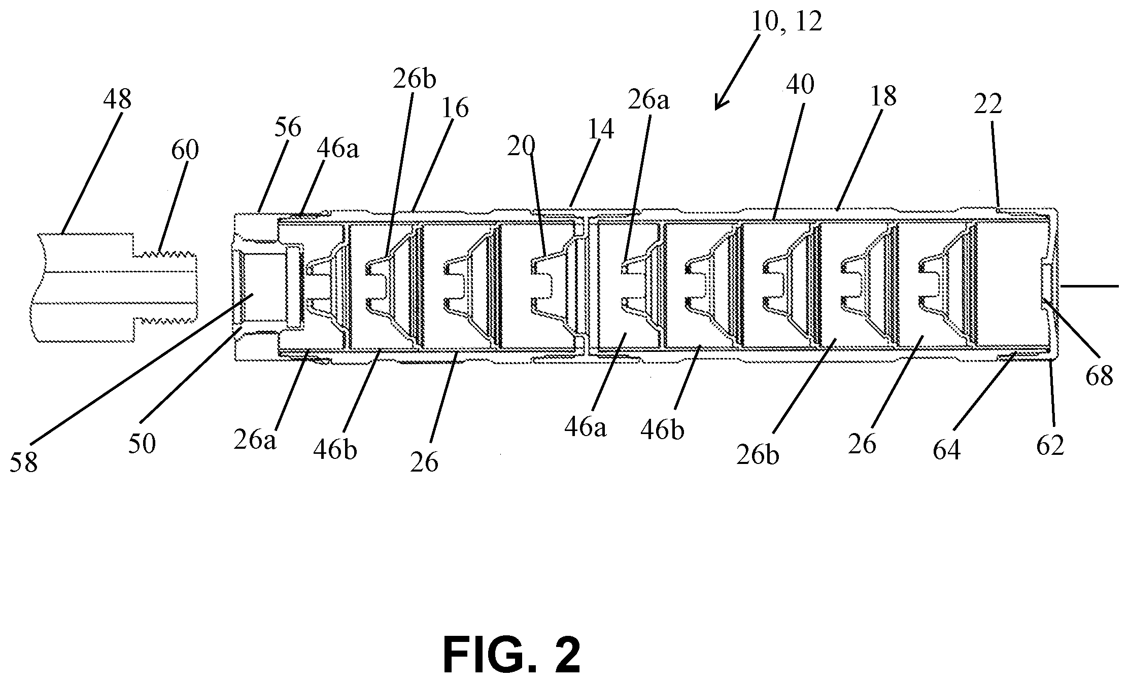
[0012] FIG. 2 is a longitudinal sectional view of the suppressor shown in FIG. 1;
[0013] FIG. 3 is an isometric view of a baffle on an enlarged scale;
[0014] FIGS. 4 and 5 are isometric longitudinal sectional views of baffles on an enlarged scale;
[0015] FIG. 6 is an exploded longitudinal sectional view of another example suppressor according to the invention;
[0016] FIGS. 7-9 are longitudinal sectional views of additional example suppressors according to the invention;
[0017] FIG. 10 is a longitudinal sectional view of example non-round suppressor configured for a pistol; and
[0018] FIG. 11 is a longitudinal sectional view of example non-round suppressor configured for a rifle.
DETAILED DESCRIPTION
[0019] FIGS. 1 and 2 show an example embodiment of a suppressor 10 arranged in a first configuration 12 for use on a pistol. The exploded view of FIG. 1 shows a coupler tube 14 and two container tubes, a first container tube 16 and a second container tube 18. For effective suppression, first tubes 16 ranging in length from about 1 inches to about 4 inches and from 0.5 inches to about 1.5 inches in diameter are considered feasible, as are second tubes also ranging in length from about 1 inches to about 4 inches and from about 0.5 inches to about 1.5 inches in diameter. Tubes 16 and 18 may be of equal length, or, as shown in this embodiment, of unequal length. In this example embodiment the container tubes 16 and 18 are hollow and cylindrical, but non-round cross sectional shapes are also feasible. As shown in this example, the coupler tube 14 may comprise at least one baffle 20 positioned therein. In this example embodiment both the container tubes 16 and 18 have outer (male) helical threads 22 at both ends. The male helical threads 22 of the container tubes 16 and 18 are engageable with internal (female) helical threads 24 arranged on opposite ends of the coupler tube 14 to permit the container tubes 16 and 18 to be coupled together as shown in FIG. 2.
[0020] For the suppressor 10 in pistol configuration 12 shown in FIG. 2, both the container tubes 16 and 18 receive a first plurality of baffles 26. In this example embodiment, the first container tube 16 is sized to receive three baffles 26, one "blast" baffle 26a, and two "standard" baffles 26b. The second container tube 18 is sized to receive five baffles 26, one blast baffle 26a and four standard baffles 26b. Although two container tubes are used in this example, other embodiments, having fewer or more container tubes are also feasible.
[0021] As shown in detail in FIGS. 3 and 4, standard baffles 26b (and baffle 20 of the coupler tube 14) comprise a truncated cone 28 extending along the firing axis 30 and defining an opening 32 arranged coaxially with firing axis 30 through which a projectile will pass. In this example embodiment the truncated cone 28 is ported, with the port 34 located near the small diameter end of the truncated cone. Non-ported baffles are also feasible, as well as multiple ports in a truncated cone. Each standard baffle 26b further comprises a spacer 36, in this example a cylindrical skirt 38 which surrounds the large diameter end of the truncated cone 28 and which projects along the firing axis 30 in the opposite direction from the truncated cone 28. Spacers 36 support the cones 28 in spaced relation when assembled in the baffle stack 40 (see FIG. 2), and may be integrally formed with the cones, or separate piece parts. In this example embodiment each standard baffle 26b has a projection 42 positioned at one end of spacer 36, and a notch 44 positioned at the opposite end of the spacer. The projections 42 and notches 44 constrain relative position of the ports 34 in cones 28, and the projections 42 of one baffle 26b are received within the notches 44 of a neighboring baffle when formed into the baffle stack 40 (see FIG. 2). In this example embodiment all of the ports 34 align with one another lengthwise along the firing axis 30 for optimum suppressor performance.
[0022] As shown in FIG. 5, in addition to the baffle cone 28 the blast baffle 26a comprises a spacer 46 which surrounds the baffle cone and has a spacer portion 46a which projects along the firing axis 30 in the direction of cone 28, and a spacer portion 46b which in the opposite direction from the cone 28. spacer portion 46b has a notch 44 which accepts a projection 42 from a standard baffle 26b to constrain relative position of the ports 34 in the standard and blast baffles when in the baffle stack 40 (FIG. 2). Blast baffle 26a in the first tube 16 is positioned in baffle stack 40 closest to the firearm muzzle 48. The spacer portion 46a provides a support interface between the baffle stack 40 and a muzzle attachment cap 50 (see also FIG. 1). Muzzle attachment cap 50 may comprise one or more component parts and has internal (female) helical threads 52 which receive outer (male) helical threads 22 on the end of the first tube 16. A shoulder 56 is positioned within the muzzle attachment cap 50 which contacts spacer portion 46a of the blast baffle 26a and secures a portion of the baffle stack within the first tube 16 against the baffle 20 within the coupler tube 14. Muzzle attachment cap 50 also defines a helically threaded opening 58 which is coaxially aligned with firing axis 30 and receives compatible threads 60 on the firearm muzzle 48 for mounting the suppressor 10 thereto.
[0023] As shown in FIGS. 1 and 2, second tube 18 also receives a second plurality of baffles 26. In this example embodiment the second tube receives one blast baffle 26a and four standard baffles 26b. Spacer portion 46a of blast baffle 26a interfaces with baffle 20 in coupler tube 14 to support the baffle stack 40 within the second tube 18. A front cap 62 captures the baffle stack 40 within the second tube 18. Front cap 62 has internal (female) threads 64 which engage outer (male) threads 22 on the second tube 18 to secure it to the second tube. Front cap 62 also defines an opening 68, coaxially aligned with firing axis 30 to allow a projectile to exit the suppressor 10.
[0024] When assembling the suppressor 10 in configuration 12 it is advantageous to align the ports 34 in the baffles 26a and 26b with the port 34 in baffle 20 within the coupler tube 14. Engagement of the projections 42 and notches 44 constrain port alignment of the baffles 26 within the stack 40, and in this example embodiment the baffles 26 in the first and second tubes 16 and 18 are readily visually aligned with the baffle 20 so that all ports 34 are aligned throughout the entire stack 40. As shown in FIG. 6, it is feasible to assemble the suppressor 10 in a configuration 70 wherein the muzzle attachment cap 50 is attached to the second tube 18 and the front cap 62 is attached to the first tube 16, thereby interchanging the positions of the first and second tubes but maintaining the orientation of the baffles 26 and 20.
[0025] Using tubes 16 and 18 of different lengths and configurable with multiple orientations of the baffle stack 40 and common helical threads on the tubes, muzzle attachment cap 50 and front cap 62 permits the suppressor 10 to be readily arranged in multiple configurations. FIG. 7 shows an example suppressor configuration 72 using only the second tube 18, four standard baffles 26b, one blast baffle 26a, the muzzle attachment cap 50 and the front cap 62. FIG. 8 shows another suppressor configuration 74 comprising the first tube 14, two standard baffles 26b, one blast baffle 26a, the muzzle attachment cap 50 and the front cap 62.
[0026] FIG. 9 shows a suppressor configuration 76 which is optimized for use with a rifle. In configuration 76 the baffles 26 in the second tube portion 18 are reversed such that the large diameter ends of cones 28 face the rifle muzzle 78 and the cones project in a direction away from the muzzle attachment cap. The baffles 26 in the first tube portion 16 are oriented such that the small diameter ends of the cones 28 face the rifle muzzle and the cones project in a direction toward the muzzle attachment cap. Testing of configuration 76 mounted on a rifle and using sub-sonic .22 LR ammunition yielded a near-field sound pressure level ranging from 107 to 110 dB. The measured sound pressure levels of configuration 76 are 5 to 6 dB down from the configuration 12 shown in FIG. 2 as well as some commercially available suppressors.
[0027] FIGS. 10 and 11 show example embodiments of suppressors having non-round cross sectional shape. Suppressor 80, shown in FIG. 10 has its baffles 26 configured with the small diameter ends of all cones 28 facing the firearm muzzle, projecting toward the muzzle attachment cap, and is thus optimized for use with a pistol. FIG. 11 shows a suppressor 82 wherein the cones 28 distal to the firearm muzzle are configured such that their large diameter ends face the muzzle and project away from the muzzle attachment cap, and is thus optimized for use with a rifle or other long gun. For both suppressors 80 and 82, the spacers 36 and cones 28 comprise segments held together in a baffle stack 40 using one or more tension rods 84. One end of the tension rod 84 is threaded and is received in a threaded receptacle 86 in the muzzle attachment cap 50. The other end of tension rod 84 is received within a cap screw 88 which applies compression to the baffle stack 40 by reacting through front cap 62.
[0028] It is advantageous to construct the baffles 20 and 26 from heat treated stainless steel, which may also be case hardened, by nitriding for example, to prevent galling and facilitate cleaning. The container tubes 16 and 18 may be made of titanium for high strength and light weight. For larger caliber projectiles, blast baffles 26a may be made of thicker gauge material than the standard baffles 26b, and more than one blast baffle may be used. It is further understood that the lengths and diameters of tubes 16 and 18 and the number of baffles 26 illustrated and described herein are by way of example of effective suppressor designs, and not meant as limiting the invention.
* * * * *
D00000
D00001
D00002
D00003
D00004
D00005
D00006
D00007
XML
uspto.report is an independent third-party trademark research tool that is not affiliated, endorsed, or sponsored by the United States Patent and Trademark Office (USPTO) or any other governmental organization. The information provided by uspto.report is based on publicly available data at the time of writing and is intended for informational purposes only.
While we strive to provide accurate and up-to-date information, we do not guarantee the accuracy, completeness, reliability, or suitability of the information displayed on this site. The use of this site is at your own risk. Any reliance you place on such information is therefore strictly at your own risk.
All official trademark data, including owner information, should be verified by visiting the official USPTO website at www.uspto.gov. This site is not intended to replace professional legal advice and should not be used as a substitute for consulting with a legal professional who is knowledgeable about trademark law.