Tensioned Support Shaft And Other Molten Metal Devices
Cooper; Paul V.
U.S. patent application number 16/790734 was filed with the patent office on 2020-06-11 for tensioned support shaft and other molten metal devices. This patent application is currently assigned to Molten Metal Equipment Innovations, LLC. The applicant listed for this patent is Molten Metal Equipment Innovations, LLC. Invention is credited to Paul V. Cooper.
| Application Number | 20200182247 16/790734 |
| Document ID | / |
| Family ID | 59274837 |
| Filed Date | 2020-06-11 |


View All Diagrams
| United States Patent Application | 20200182247 |
| Kind Code | A1 |
| Cooper; Paul V. | June 11, 2020 |
TENSIONED SUPPORT SHAFT AND OTHER MOLTEN METAL DEVICES
Abstract
A vertical member, which is preferably a support post used in a molten metal pump, includes a ceramic tube and tensioning structures to add a compressive load to the tube along its longitudinal axis. This makes the tube less prone to breakage. A device, such as a pump, used in a molten metal bath includes one or more of such vertical members.
| Inventors: | Cooper; Paul V.; (Chesterland, OH) | ||||||||||
| Applicant: |
|
||||||||||
|---|---|---|---|---|---|---|---|---|---|---|---|
| Assignee: | Molten Metal Equipment Innovations,
LLC Middlefield OH |
||||||||||
| Family ID: | 59274837 | ||||||||||
| Appl. No.: | 16/790734 | ||||||||||
| Filed: | February 14, 2020 |
Related U.S. Patent Documents
| Application Number | Filing Date | Patent Number | ||
|---|---|---|---|---|
| 16144873 | Sep 27, 2018 | |||
| 16790734 | ||||
| 15406515 | Jan 13, 2017 | 10267314 | ||
| 16144873 | ||||
| 62278314 | Jan 13, 2016 | |||
| Current U.S. Class: | 1/1 |
| Current CPC Class: | F04D 7/065 20130101; F04D 29/628 20130101; F04D 13/06 20130101; F04D 29/605 20130101; F04D 29/026 20130101; F04D 29/043 20130101; F05D 2300/20 20130101 |
| International Class: | F04D 7/06 20060101 F04D007/06; F04D 29/62 20060101 F04D029/62; F04D 29/043 20060101 F04D029/043 |
Claims
1. A support post for use in a molten metal pump, the support post comprising: (a) a tube defining a hollow channel and having a first tube end and a second tube end; (b) a tension rod positioned inside of the hollow channel and having a first rod end positioned outside of the hollow channel beyond the first tube end and a second rod end positioned outside the hollow channel beyond the second tube end; (c) a bottom cap that is coupled to the first rod end, and that has a first end that presses against and exerts axial pressure on the first tube end; and (d) a top cap that is coupled to the second rod end, and that has a first cap end that presses against and exerts axial pressure on the second tube end; wherein the tension rod is configured to provide a compressive load to the tube in response to being coupled to the bottom cap and the top cap.
2. The support post of claim 1, wherein the tube comprises one or both of ceramic and graphite.
3. The support post of claim 1, wherein the tube comprises silicon carbide.
4. The support post of claim 1, wherein the tube further comprises an interior surface, and wherein the tension rod is separated from the interior surface defining a gap between the tension rod and the interior surface.
5. The support post of claim 1, wherein the bottom cap is made of graphite.
6. The support post of claim 1, wherein the bottom cap and top cap are each comprised of one or more of graphite and silicon carbide.
7. The support post of claim 1, wherein the bottom cap comprises a two-piece assembly that is configured to isolate the tension rod from a molten metal environment.
8. The support post of claim 1, wherein the second rod end is configured to protrude through the top cap.
9. The support post of claim 1 that is configured so the second end of the tension rod can pass through a superstructure of a molten metal pump.
10. The support post of claim 1 that further comprises a first support post end configured to be attached to a superstructure of a molten metal pump and a second support post end configured to be connected to a molten metal pump base.
11. The support post of claim 1, wherein the top cap further comprises a housing and a first spring positioned in the housing.
12. The support post of claim 11, wherein part of the first spring is positioned outward of the housing.
13. The support post of claim 11, wherein the second end of the tension rod is positioned inside of the first spring.
14. The support post of claim 11, wherein the top cap further comprises a spring cover that helps retain the first spring.
15. The support post of claim 1 that further comprises a fastener connected to the second end of the tension rod.
16. The support post of claim 15, wherein the fastener is threaded onto the second end of the tension rod.
17. The support post of claim 1, wherein the bottom cap has a housing and the first end of the tension rod is connected to the housing.
18. The support post of claim 17, wherein the tension rod is connected to the housing by a threaded connection.
19. A molten metal pump comprising: (a) a superstructure; (b) a motor having a motor shaft with a first end connected to the motor and a second end; (c) a rotor shaft operatively coupled to the second end of the motor shaft; (d) the support post of claim 1 having a first end connected to the superstructure, and; (e) a base connected to a second end of the support post.
20. The molten metal pump of claim 19 further comprising a rotor connected to the rotor shaft.
21. The molten metal pump of claim 19 further comprising a gas injection tube coupled to the superstructure.
22. The molten metal pump of claim 20 further comprising a pump chamber in the base, wherein the rotor is positioned in the pump chamber.
23. The molten metal pump of claim 19, wherein the tube comprises an interior surface, and wherein the tension rod is separated from the interior surface defining a gap between the tension rod and the interior surface.
24. The molten metal pump of claim 19, wherein the bottom cap and top cap are each comprised of one or more of graphite and silicon carbide.
25. The molten metal pump of claim 11, wherein the bottom cap comprises a two-piece assembly that is configured to isolate the tension rod from a molten metal environment.
26. The molten metal pump of claim 11, wherein the second rod end is configured to protrude through the top cap.
Description
CROSS-REFERENCE TO RELATED APPLICATIONS
[0001] This application is a continuation of, and claims priority to U.S. patent application Ser. No. 16/144,873, filed Sep. 27, 2018, and entitled "Tensioned Support Shaft and Other Molten Metal Devices" which is a continuation of, and claims priority to, U.S. patent application Ser. No. 15/406,515 (Now U.S. Pat. No. 10,267,314), filed Jan. 13, 2017, and entitled "Tensioned Support Shaft and Other Molten Metal Devices," which claims the benefit of U.S. Provisional Application Ser. No. 62/278,314, filed Jan. 13, 2016, and entitled "Tensioned Support Shaft and Other Molten Metal Devices," the contents of each of the foregoing applications, are incorporated herein by reference, to the extent such contents do not conflict with the present disclosure.
FIELD OF THE INVENTION
[0002] The invention relates to tensioned support shafts that may be used in various devices, particularly pumps for pumping molten metal.
BACKGROUND OF THE INVENTION
[0003] As used herein, the term "molten metal" means any metal or combination of metals in liquid form, such as aluminum, copper, iron, zinc and alloys thereof. The term "gas" means any gas or combination of gases, including argon, nitrogen, chlorine, fluorine, Freon, and helium, which are released into molten metal.
[0004] Known molten-metal pumps include a pump base (also called a housing or casing), one or more inlets (an inlet being an opening in the housing to allow molten metal to enter a pump chamber), a pump chamber of any suitable configuration, which is an open area formed within the housing, and a discharge, which is a channel or conduit of any structure or type communicating with the pump chamber (in an axial pump the chamber and discharge may be the same structure or different areas of the same structure) leading from the pump chamber to an outlet, which is an opening formed in the exterior of the housing through which molten metal exits the casing. An impeller, also called a rotor, is mounted in the pump chamber and is connected to a drive system. The drive shaft is typically an impeller shaft connected to one end of a motor shaft, the other end of the drive shaft being connected to an impeller. Often, the impeller (or rotor) shaft is comprised of graphite and/or ceramic, the motor shaft is comprised of steel, and the two are connected by a coupling. As the motor turns the drive shaft, the drive shaft turns the impeller and the impeller pushes molten metal out of the pump chamber, through the discharge, out of the outlet and into the molten metal bath. Most molten metal pumps are gravity fed, wherein gravity forces molten metal through the inlet and into the pump chamber as the impeller pushes molten metal out of the pump chamber. Other molten metal pumps do not include a base or support posts and are sized to fit into a structure by which molten metal is pumped. Most pumps have a metal platform, or super structure, that is either supported by a plurality of support posts attached to the pump base, or unsupported if there is no base. The motor is positioned on the superstructure, if a superstructure is used.
[0005] This application incorporates by reference the portions of the following publications that are not inconsistent with this disclosure: U.S. Pat. No. 4,598,899, issued Jul. 8, 1986, to Paul V. Cooper, U.S. Pat. No. 5,203,681, issued Apr. 20, 1993, to Paul V. Cooper, U.S. Pat. No. 5,308,045, issued May 3, 1994, by Paul V. Cooper, U.S. Pat. No. 5,662,725, issued Sep. 2, 1997, by Paul V. Cooper, U.S. Pat. No. 5,678,807, issued Oct. 21, 1997, by Paul V. Cooper, U.S. Pat. No. 6,027,685, issued Feb. 22, 2000, by Paul V. Cooper, U.S. Pat. No. 6,124,523, issued Sep. 26, 2000, by Paul V. Cooper, U.S. Pat. No. 6,303,074, issued Oct. 16, 2001, by Paul V. Cooper, U.S. Pat. No. 6,689,310, issued Feb. 10, 2004, by Paul V. Cooper, U.S. Pat. No. 6,723,276, issued Apr. 20, 2004, by Paul V. Cooper, U.S. Pat. No. 7,402,276, issued Jul. 22, 2008, by Paul V. Cooper, U.S. Pat. No. 7,507,367, issued Mar. 24, 2009, by Paul V. Cooper, U.S. Pat. No. 7,906,068, issued Mar. 15, 2011, by Paul V. Cooper, U.S. Pat. No. 8,075,837, issued Dec. 13, 2011, by Paul V. Cooper, U.S. Pat. No. 8,110,141, issued Feb. 7, 2012, by Paul V. Cooper, U.S. Pat. No. 8,178,037, issued May 15, 2012, by Paul V. Cooper, U.S. Pat. No. 8,361,379, issued Jan. 29, 2013, by Paul V. Cooper, U.S. Pat. No. 8,366,993, issued Feb. 5, 2013, by Paul V. Cooper, U.S. Pat. No. 8,409,495, issued Apr. 2, 2013, by Paul V. Cooper, U.S. Pat. No. 8,440,135, issued May 15, 2013, by Paul V. Cooper, U.S. Pat. No. 8,444,911, issued May 21, 2013, by Paul V. Cooper, U.S. Pat. No. 8,475,708, issued Jul. 2, 2013, by Paul V. Cooper, U.S. patent application Ser. No. 12/895,796, filed Sep. 30, 2010, by Paul V. Cooper, U.S. patent application Ser. No. 12/877,988, filed Sep. 8, 2010, by Paul V. Cooper, U.S. patent application Ser. No. 12/853,238, filed Aug. 9, 2010, by Paul V. Cooper, U.S. patent application Ser. No. 12/880,027, filed Sep. 10, 2010, by Paul V. Cooper, U.S. patent application Ser. No. 13/752,312, filed Jan. 28, 2013, by Paul V. Cooper, U.S. patent application Ser. No. 13/756,468, filed Jan. 31, 2013, by Paul V. Cooper, U.S. patent application Ser. No. 13/791,889, filed Mar. 8, 2013, by Paul V. Cooper, U.S. patent application Ser. No. 13/791,952, filed Mar. 9, 2013, by Paul V. Cooper, U.S. patent application Ser. No. 13/841,594, filed Mar. 15, 2013, by Paul V. Cooper, and U.S. patent application Ser. No. 14/027,237, filed Sep. 15, 2013, by Paul V. Cooper.
[0006] Three basic types of pumps for pumping molten metal, such as molten aluminum, are utilized: circulation pumps, transfer pumps and gas-release pumps. Circulation pumps are used to circulate the molten metal within a bath, thereby generally equalizing the temperature of the molten metal. Circulation pumps may be used in any vessel, such as in a reverbatory furnace having an external well. The well is usually an extension of the charging well, in which scrap metal is charged (i.e., added).
[0007] Standard transfer pumps are generally used to transfer molten metal from one structure to another structure such as a ladle or another furnace. A standard transfer pump has a riser tube connected to a pump discharge and supported by the superstructure. As molten metal is pumped it is pushed up the riser tube (sometimes called a metal-transfer conduit) and out of the riser tube, which generally has an elbow at its upper end, so molten metal is released into a different vessel from which the pump is positioned.
[0008] Gas-release pumps, such as gas-injection pumps, circulate molten metal while introducing a gas into the molten metal. In the purification of molten metals, particularly aluminum, it is frequently desired to remove dissolved gases such as hydrogen, or dissolved metals, such as magnesium. As is known by those skilled in the art, the removing of dissolved gas is known as "degassing" while the removal of magnesium is known as "demagging." Gas-release pumps may be used for either of both of these purposes or for any other application for which it is desirable to introduce gas into molten metal.
[0009] Gas-release pumps generally include a gas-transfer conduit having a first end that is connected to a gas source and a second end submerged in the molten metal bath. Gas is introduced into the first end and is released from the second end into the molten metal. The gas may be released downstream of the pump chamber into either the pump discharge or a metal-transfer conduit extending from the discharge, or into a stream of molten metal exiting either the discharge or the metal-transfer conduit. Alternatively, gas may be released into the pump chamber or upstream of the pump chamber at a position where molten metal enters the pump chamber. The gas may also be released into any suitable location in a molten metal bath.
[0010] Molten metal pump casings and rotors often employ a bearing system comprising ceramic rings wherein there are one or more rings on the rotor that align with rings in the pump chamber (such as rings at the inlet and outlet) when the rotor is placed in the pump chamber. The purpose of the bearing system is to reduce damage to the soft, graphite components, particularly the rotor and pump base, during pump operation.
[0011] Generally, a degasser (also called a rotary degasser) includes (1) an impeller shaft having a first end, a second end and a passage for transferring gas, (2) an impeller, and (3) a drive source for rotating the impeller shaft and the impeller. The first end of the impeller shaft is connected to the drive source and to a gas source and the second end is connected to the impeller.
[0012] Generally a scrap melter includes an impeller affixed to an end of a drive shaft, and a drive source attached to the other end of the drive shaft for rotating the shaft and the impeller. The movement of the impeller draws molten metal and scrap metal downward into the molten metal bath in order to melt the scrap. A circulation pump is preferably used in conjunction with the scrap melter to circulate the molten metal in order to maintain a relatively constant temperature within the molten metal.
[0013] The materials forming the components that contact the molten metal bath should remain relatively stable in the bath. Structural refractory materials, such as graphite or ceramics, that are resistant to disintegration by corrosive attack from the molten metal may be used. As used herein "ceramics" or "ceramic" refers to any oxidized metal (including silicon) or carbon-based material, excluding graphite, or other ceramic material capable of being used in the environment of a molten metal bath. "Graphite" means any type of graphite, whether or not chemically treated. Graphite is particularly suitable for being formed into pump components because it is (a) soft and relatively easy to machine, (b) not as brittle as ceramics and less prone to breakage, and (c) less expensive than ceramics.
[0014] Ceramic, however, is more resistant to corrosion by molten aluminum than graphite. It would therefore be advantageous to develop vertical members used in a molten metal device that are comprised of ceramic, but less costly than solid ceramic members, and less prone to breakage than normal ceramic.
SUMMARY OF THE INVENTION
[0015] The present invention relates to a vertical member used in a molten metal device. The member is comprised of a hollow ceramic outer shell that has tension applied along a longitudinal axis of a rod therein. When such tension is applied to the rod, the ceramic outer shell is much less prone to breakage. One type of vertical member that may employ the invention is a support post. The disclosure also relates to pump including such support posts and to other molten metal devices.
BRIEF DESCRIPTION OF THE DRAWINGS
[0016] FIG. 1 is a perspective view of a pump for pumping molten metal, which may include rotor shaft and plurality of support posts, in accordance with various embodiments.
[0017] FIG. 2A is a profile view of a support post, in accordance with various embodiments.
[0018] FIG. 2B is an exploded view of a support post, in accordance with various embodiments.
[0019] FIG. 3A is a cross sectional view of a support post, in accordance with various embodiments.
[0020] FIG. 3B is a cross sectional view of a bottom portion of a support post, in accordance with various embodiments.
[0021] FIG. 3C is a cross sectional view of a top portion of a support post, in accordance with various embodiments.
[0022] FIGS. 3D-3Z illustrate various components of exemplary support posts in accordance with various embodiments of the disclosure.
[0023] FIGS. 4A-4C illustrate a rotor plug in accordance with exemplary embodiments of the disclosure.
[0024] FIGS. 5A-1, 5A-2 and FIGS. 5B-5R illustrate a support post and various components thereof in accordance with additional exemplary embodiments of the disclosure.
[0025] FIGS. 6A-6J illustrate a rotor shaft and various components thereof in accordance with additional exemplary embodiments of the disclosure.
[0026] FIGS. 7A-7P illustrate a coupling and various components thereof in accordance with additional exemplary embodiments of the disclosure.
[0027] FIGS. 8A-8T illustrate a pump and various components thereof in accordance with exemplary embodiments of the disclosure.
DETAILED DESCRIPTION OF PREFERRED EMBODIMENTS
[0028] For any device described herein, any of the components that contact the molten metal are preferably formed by a material that can withstand the molten metal environment. Preferred materials are oxidation-resistant graphite and ceramics, such as silicon carbide.
[0029] Reference will now be made in detail to the present exemplary embodiments of the invention, examples of which are illustrated in the accompanying drawings. FIG. 1 depicts a molten metal pump 100 according to exemplary embodiments of the disclosure. When in operation, pump 100 is typically positioned in a molten metal bath in a pump well, which is typically part of the open well of a reverbatory furnace. Pump 100 includes motor 120, superstructure 130, support shafts 140, drive shaft 122, rotor 110, base 160, and a gas transfer system 170. The gas transfer system 170 may comprise gas-transfer foot 172 and gas-transfer tube 174.
[0030] The components of pump 100 or portions thereof that are exposed to the molten metal (such as support shafts 140, drive shaft 122, rotor 110, base 160, gas-transfer foot 172 and gas-transfer tube 174) are preferably formed of structural refractory materials, which are resistant to degradation in the molten metal.
[0031] Pump 100 need not be limited to the structure depicted in FIG. 1, but can be any structure or device for pumping or otherwise conveying molten metal, such as the pump disclosed in U.S. Pat. No. 5,203,681 to Cooper, or an axial pump having an axial, rather than tangential, discharge. Preferred pump 100 includes a base 160 (e.g., a pump base) for being submersed in a molten metal bath. Pump base 160 preferably includes a generally nonvolute pump chamber 210, such as a cylindrical pump chamber or what has been called a "cut" volute, although pump base 160 may have any shape pump chamber suitable of being used, including a volute-shaped chamber. Pump chamber 210 may be constructed to have only one opening, either in its top or bottom, if a tangential discharge is used, since only one opening is required to introduce molten metal into pump chamber 210. Generally, pump chamber 210 has two coaxial openings of the same diameter and usually one is blocked by a flow blocking plate mounted on, or formed as part of, rotor 110. Base 160 further includes a tangential discharge 220 (although another type of discharge, such as an axial discharge may be used) in fluid communication with pump chamber 210.
[0032] In this embodiment, one or more support posts 140 connect base 160 to a superstructure 130 of pump 100 thus supporting superstructure 130. Pump 100 could be constructed so there is no physical connection between the base and the superstructure, wherein the superstructure is independently supported. The motor, drive shaft and rotor could be suspended without a superstructure, wherein they are supported, directly or indirectly, to a structure independent of the pump base.
[0033] Motor 120, which can be any structure, system or device suitable for driving pump 100, but is preferably an electric or pneumatic motor, is positioned on superstructure 130 and is connected to an end of a drive shaft 122. A drive shaft 122 can be any structure suitable for rotating an impeller, and preferably comprises a motor shaft (not shown) coupled to a rotor shaft. The motor shaft has a first end and a second end, wherein the first end of the motor shaft connects to motor 120 and the second end of the motor shaft connects to the coupling. Rotor shaft 124 has a first end and a second end, wherein the first end is connected to the coupling and the second end is connected to rotor (or impeller) 110.
[0034] Rotor 110 can be any rotor suitable for use in a molten metal pump and the term "rotor," as used in connection with this disclosure, means any device or rotor used in a molten metal device to displace molten metal.
[0035] As described herein, support post (also referred to herein as support shaft) 140 may be a structure that is configured to support a motor and/or superstructure of a molten metal pump. In various embodiments and with reference to FIG. 2A and FIG. 2B, a support post 240, suitable for use as support post 140, comprises a tube 250, a tension rod 242, a bottom cap 246, and a top cap 244. Tension rod 242 may be disposed within a cavity 251 defined by the inner wall 149 of tube 250. Tension rod 242 may be attached at one and to bottom cap 246 and at its other end to top cap 244. In this embodiment, tension rod 242 is placed in tension by bottom cap 246 and top cap 244, creating a compressive load on tube 250.
[0036] Tube 250, illustrated in more detail in FIGS. 3L-3N, preferably comprises a first end 250A and a second end 250B. Bottom cap 246 is configured to receive, engage, retain, and/or otherwise mate to the first end 250A of tube 250. Bottom cap 246 may also be operatively coupled to the first end 242A of tension rod 242. Top cap 244 may be configured to receive, engage, mate with, couple to, and/or otherwise receive the second end 250B of tube 250. Similarly, top cap 244 may be configured to operatively couple to, engage, and/or otherwise mate with the second end 242B of tension rod 242 and/or a portion of tension rod 242 adjacent to the second end 242B of tension rod 242.
[0037] In various embodiments, tube 250 may comprise inner or interior surface 149 that defines a hollow channel or cavity 251 within tube 250. As discussed herein, tension rod 242 may be installable within and/or housed by tube 250 within its hollow channel. Moreover, tension rod 242 may be separated from the interior surface of tube 250. In this regard, there may be a gap defined between tension rod 242 and the interior surface 149 of tube 250.
[0038] In various embodiments, tube 250 may be a homogeneous ceramic material. For example, tube 250 may be formed of a ceramic material such as, for example, silicon carbide.
[0039] FIGS. 30-3Q illustrate tension rod 242 in greater detail. Tension rod 242 can be formed of, for example, steel. Exemplary tension rods have a length of about 38.75 to about 45.75 inches and can have a diameter of about one inch. First end 242A can include a flat face 242D, while second end 242B can include a tip that includes a first portion 242E, which is cylindrical in shape and which has a smaller diameter than a middle section 242G, and a second section 242F that is frusto-conical in shape.
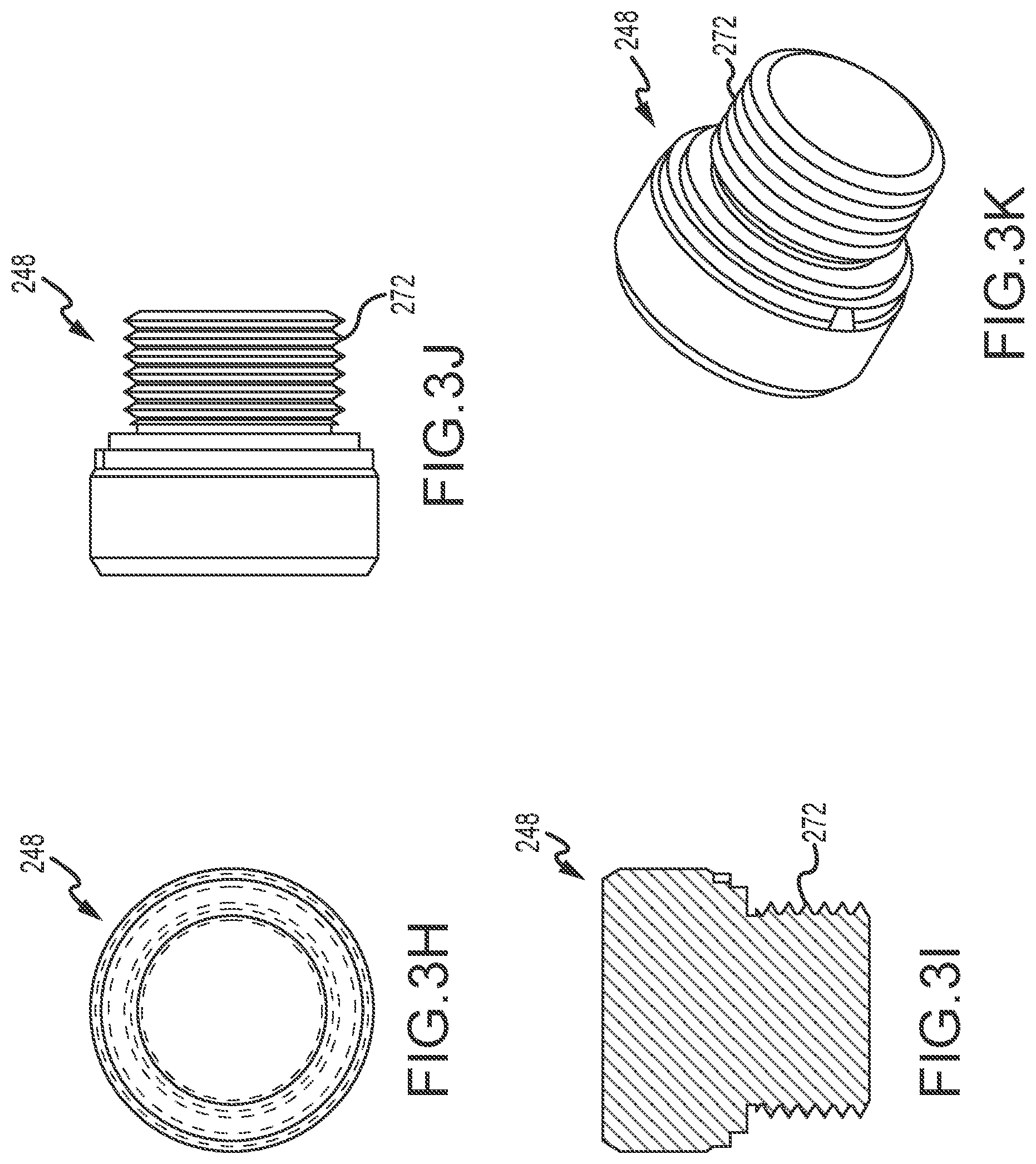
[0040] Top cap 244 and bottom cap 246 are preferably made of graphite. In various embodiments, and with reference to FIG. 2B, bottom cap 246 is in the form of an assembly. Bottom cap 246 comprises a housing 247 and a cover 248. Cover 248, may be operatively coupled to and/or may be installable within housing 247. For example, cover 248 may comprise a threaded portion 272 that is configured to thread into or otherwise engage with a receivable channel or cylinder within housing 247. Moreover, bottom cap 246 may comprise a fastener 254-1 and a washer 252-1. Fastener 254-1 and/or washer 252-1 is configured to engage the first end 242A of tension rod 242.
[0041] Bottom cap 246 and portions thereof are illustrated in greater detail in FIGS. 3D-3K. Housing 247 includes a top portion 260 including a top surface 261 having a recess 262 formed therein for receiving tube 250, a channel 264 for receiving tension rod 242, and an opening 266 for receiving cover 248 through a bottom portion 268 of housing 247. Recess 262, and channel 264 and opening 266 can be coaxial. As illustrated in FIG. 3E. a portion of opening 266 can be threaded, so as to enable engagement with threaded portion 272 of cover 248. Housing 247 can also include a cavity 270.
[0042] In various embodiments, top cap 244 is an assembly comprising housing 243 and spring 256 (illustrated in more detail in FIGS. 3U-3W). Spring 256 is installable within housing 243 of top cap 244. Second end 242B of tension rod 242 is configured to pass through and protrude from housing 243 of top cap 244. Spring 256 is installable over second end 242B of tension rod 242. In this regard, spring 256 is preferably configured to add tension to rod 242. Top cap 244 may further comprise a spring cover 257 (illustrated in more detail in FIGS. 3X-3Z), one or more washers including, for example, washer 252-2 and washer 252-3, and a fastener 254-2. Spring cover 257 as shown is installable over spring 256. One or more washers such as, for example, washer 252-2 and washer 252-3 may be installable on either side of spring cover 257. In this regard, washer 252-2 and/or washer 252-3 are configured to retain spring 256 within spring cover 257. Moreover, fastener 254-2 may be configured to engage and/or may be installable on the second end 242B of tension rod 242. Second end 242B of tension rod 242 may comprise a threaded portion 242C. Fastener 254-2 may be configured to engage and/or may be installable on the threaded portion 242C. Fastener 254-2 may also be configured to seat against and/or retain one or more of washer 252-2, washer 252-3, spring 256, and/or spring cover 257. In this regard, the assembly within top cap 244 is preferably configured to create a load on tension rod 242 thus creating a compressive load on tube 250.
[0043] FIGS. 3R-3T illustrate housing 243 in greater detail. Housing 243 includes a first opening 274, a passage 276, and a second opening 278, all of which can be coaxial. Recess 243 can be configured to receive a portion of tube 250, passage 276 can be configured to receive tension rod 242 therethrough, and recess 274 can be configured to receive washer 252-2, spring 256, spring cover 257, washer 252-3, and fastener 254-2.
[0044] In various embodiments, and with reference to FIG. 3A, FIG. 3B, and FIG. 3C, a support post 340, which may be the same or similar to support post 240, may comprise portions that are self-contained. For example, bottom cap 346 may create a self-contained assembly when tube 350 is installed with and/or engages bottom cap 346. In this regard, bottom cap 346 may be configured to isolate a tension rod 342 from a molten metal environment when support post 340 is installed on a molten metal pump. In operation, portions of support post 340 would be submerged within a molten metal bath. In order to prevent corrosion of tension rod 342 (which can be the same as or similar t tension rod 242), tube 350 (which can be the same as or similar to tube 250) and bottom cap 346 may be configured to form a liquid tight assembly that prevents molten metal (e.g., molten aluminum) from reaching tension rod 342.
[0045] In various embodiments, and as discussed herein, bottom cap 346 may comprise various parts including washers such as, for example, washer 352-1 and fasteners such as, for example, fastener 354-1. These washers and fasteners may be separately removable components or they may be integrally formed within one or more components of bottom cap 346. For example, washer 352-1 may be integrally formed within housing 347. In this regard, a first end 342A of tension rod 342 may be configured to pass through housing 347 and/or washer 352-1. Moreover, the first end 342A of tension rod 342 may comprise a threaded portion 342C that threads into and/or threads through housing 347 and/or washer 352-1. Housing 347 and/or cover 348 may also comprise and/or may be configured with an integrally formed fastener 354-1. In this regard, first end 342A of tension rod 342 may be configured to thread through the integral fastener 354-1 and/or may be capable of having the integral fastener threaded on the threaded portion 342C of the first end 342A of tension rod 342.
[0046] In various embodiments, top cap 344 may be an assembly that is configured to receive a threaded portion 342D of a second end 342B of tension rod 342. Top cap 344 may comprise various components including, for example, washers 352-2 and 352-3, fastener 354-2, spring 356, and/or spring cover 357. One or more of these elements may be integrally formed within top cap 344. For example, washer 352-2 may be integrally formed within or as part of top cap 344. Moreover, top cap 344 may be a multi-piece assembly that allows for installation of various components including, for example, spring 356 and/or spring cover 357. Top cap 344 may be, for example, a clamshell assembly having two halves that thread together. A first portion 344A of the clamshell assembly of top cap 344 may comprise a washer 352-2 that is configured to provide a seat or loading surface for spring 356 and a seating surface for spring cover 357. Moreover, a second portion 344B of a clamshell assembly of top cap 344 may comprise an integrally formed fastener 354-2 and washer 352-3. In this regard, the first portion 344A and second portion 344B of the clamshell assembly of top cap 344 may be operatively coupled to one another with various fasteners, threading and/or the like.
[0047] In various embodiments, the second end 342B of tension rod 342 may comprise a threaded portion 342D that is configured to thread through and/or pass through one or more components of top cap 344, including, for example, spring 356, washers 352-2 and 352-3, spring cover 357, fastener 354-2, housing 343, and/or the like. In this regard, the second end 342B of tension rod 342 may comprise a threaded portion 342D and a guide portion 342E having a tip with a reduced diameter and/or a chamfered edge.
[0048] In various embodiments, the second end 342B of tension rod 342 may pass through top cap 344 allowing engagement with a base or superstructure of a molten metal pump.
[0049] FIGS. 5A-5C illustrate a support post 540, also suitable as support post 140, in accordance with additional exemplary embodiments. Support post 540 includes a tube 550, a tension rod 542, a bottom cap 546, and a top cap 544. Tension rod 542 can be disposed within a cavity 551, which is defined by an inner wall 549 or tube 550.
[0050] FIG. 5D and FIGS. 5F-5H illustrate bottom cap 546 in greater detail. Bottom cap 546 includes a housing 548 to receive a first end 542A of tension rod 542. In the illustrated example, housing 548 includes a recess 551 to threadedly or otherwise engage with first end 542A of tension rod 542. As illustrated in FIG. 5H, recess 551 can include a substantially cylindrical section 560 and a conical section 562 that comes to a point. Housing 548 also includes a recess 553 to receive a first end 550A of tube 550. Recesses 552 and 551 can be coaxial. As illustrated in FIG. 5G, recess 553 includes a tapered section 564 and a cylindrical section 566. Recess 553 includes a flat surface 555, having a hole therethrough to receive first end 542A of tension rod 542.
[0051] Top cap 544, illustrated in greater detail in FIGS. 5E and 5O-5R, includes a housing 570 to receive a second end 542B of tension rod 542. In the illustrated example, housing 570 includes a recess 571 to threadedly or otherwise engage with second end 542B of tension rod 542. Recess 571 can include a first substantially cylindrical section 572, a second substantially cylindrical portion 573, and a conical section 574 that comes to a point 575. Housing 570 or top cap 544 also include a recess 576 that includes a (e.g., flat) surface 577 that engages with and can contact second send 550B of tube 550. Top cap 544 can also include a notch on at least a portion of housing 570. Top cap 544 can also include a hole 580 extending partially or entirely through housing 570.
[0052] Top cap 544 and bottom cap 546 can be attached (e.g., threadedly) to second end 542B and first end 542A, respectively, of tension rod 542 to apply a compressive load to tube 550.
[0053] FIGS. 51-5K illustrate tube 550 in greater detail. Tube 550 includes a first cylindrical portion 582, a tapered portion 586, and optionally a second cylindrical portion 588. As illustrated in FIG. 5J, cavity 551 extends through portions 582, 586, and 588. Cavity 551 can be tapered, such that an opening at first end 550A is smaller than the opening of cavity 551 at second end 550B. For example, the opening at second end 550B can have a diameter of about 1.6 inches and the opening at first end can have a diameter of about 1.4 inches, when a length L of tube 550 ranges from about 27.9 to about 38.5 inches.
[0054] First end 550A of tube 550 includes tapered portion 586 and optional cylindrical portion 588. As illustrated in FIG. 5C, portions 586 and 588 can be received by housing 548 of bottom cap 546. First end 550A also include a face 590, which can be flat or substantially flat, so as to engage (e.g., contact) surface 555 of bottom cap 546. Similarly, second end 550B includes a face 592 that can be flat and configured to engage with and/or contact surface 577 of top cap 544. A portion of first cylindrical portion 582 can be received within recess 576, so that face 592 contacts surface 577. Recess 576 can be, for example, about 3/4 inches thick with a diameter of about 5.05 inches.
[0055] FIGS. 5L-5N illustrate tension rod 542 in greater detail. As previously noted, tension rod includes first end 542A, which includes an engagement mechanism 594, such as threads. Similarly, second end 542B includes an engagement mechanism 596, such as threads. Engagement mechanisms 594 and 596 allow top cap 544 and bottom cap 546 to attach to tension rod 542, so as to allow a compressive force to be applied to tube 550. As illustrated, ends 542C and 542D or tension rod 542 can include a flat face that is perpendicular to the axis of tension rod 542.
[0056] FIGS. 6A-6J illustrate a rotor shaft in accordance with various embodiments of the disclosure. Rotor shaft 600 includes an outer tube 602, an inner rod 604, a cap 606, and a structure 618. Rotor shaft 600 is attached to a rotor 608.
[0057] Outer tube 602 includes a first end 610, a second end 612, and an outer surface 612. Outer tube 602 includes a cavity 614 spanning therethrough to receive inner rod 604. Outer tube 602 can be formed of, for example, a ceramic, such as silicon carbide.
[0058] Inner rod 604 can include a rod (e.g., steel) that is partially threaded--e.g., including first (e.g., threaded) portion 615 and second (e.g., threaded) portion 616. Structure 618, such as a nut, can be threadedly attached to second threaded portion 616 to retain rotor 608 proximate or adjacent second end 612. First portion 615 can be used to engage with cap 606 to retain cap 606 proximate or adjacent first end 610. Rotor shaft 600 can also include a washer 620--e.g., between rotor 608 and nut 618.
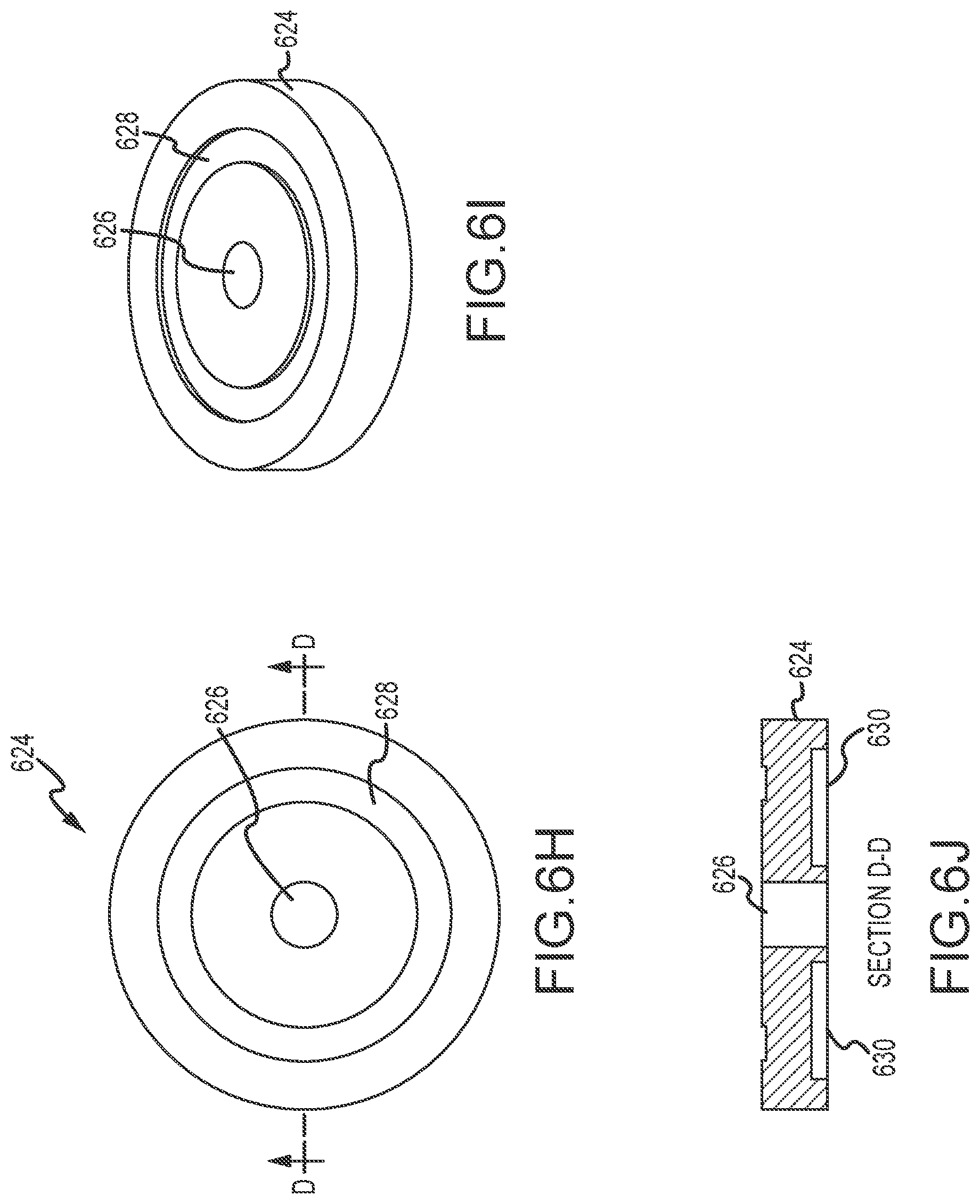
[0059] Cap 606 and portions thereof are illustrated in more detail in FIGS. 6D-6J. Cap 606 includes a first section 622 having a top section 623 configured to engage with a coupling (an exemplary coupling is described in more detail below) and a bottom section 624 configured to engage with outer tube 602 and inner rod 604. Top section 622 can be of substantially tubular shape, having one or more L-shaped openings 626 formed therein to connect cap 606 to a coupling. Bottom section 624 includes a cavity 626 to receive inner rod 604, a first recess 628 to receive a bottom portion of first section 622, and a third recess 630 to receive a top surface of first end 610 of outer tube 602. Cap 606 can be formed of, for example, steel. Further, cap 606 can be configures, such that when cap 606 is connected to a coupling and the coupling drives rotor shaft 600, rotor shaft 600 moves in a direction that tightens the cap against first end 610 of outer tube 602 to apply axial pressure on outer tube 602.
[0060] Rotor shaft 600 can also include a rotor plug 400, illustrated in FIGS. 4A-4C. Rotor plug 400 can be received by (e.g., threadedly) by rotor 608, as illustrated in FIG. 6B. Rotor plug 400 includes threads 402 to engage with rotor 608. Rotor plug 400 can also include recess 404 to facilitate threaded engagement of rotor plug with rotor 608.
[0061] Rotor 608 connects to second end 612 of rotor shaft 602. Rotor 608 includes one or more (e.g., a plurality) of spaced-apart blades 632-636, a passageway 638 for receiving second (e.g., threaded) end 616 of inner rod 604, a cavity for retaining structure 618 and for receiving rotor plug 400.
[0062] FIGS. 7A-7P illustrate a coupling 700 suitable for use with a rotor shaft for a molten metal device. Coupling 700 includes a body 702, one or more securing structures 704-708, and one or more tightening structures 710,712, and 714. Coupling 700 can be used to couple rotor shaft 602 to, for example, a motor shaft (also referred to herein as a motor post). Each of the components of coupling 700 can be formed of steel (e.g., hardened steel).
[0063] Body 702 includes an opening 716 to receive a motor shaft from a motor, described in more detail below, and an outer surface 718 to be received by an inner surface 640 of cap 606 of rotor shaft 600. Body 702 also includes openings 720, 722 and 724 to receive (e.g., threadedly) one or more (e.g., manual) tightening structures 710-714. Body 702 also includes opening 726 and 728 to receive a rod 730, which can be a hardened steel rod having, for example a diameter of about 0.75 inches and a length of about 4.75 inches. Body 702 can further include a notch 732 and/or recessed region 734. In the illustrated example, opening 716 includes recessed region 734, a first section 736, and a second section 738. A diameter of the opening of recessed region 734 is larger than the diameter of the opening of first region 736, and the diameter of the opening of first region 736 is larger than a diameter of the opening of second region 738. Each of the recessed region 734, the opening in the first region, and the opening in the second region can be cylindrical.
[0064] Securing structures 704-708 can be in the form of tubes formed of, for example, schedule 40 pipe, having a one inch diameter (e.g., about 1.049'' ID and about 1.315'' OD) and a length of about 3.5 inches. Securing structures 704-708 can be welded to outer surface 718--e.g., evenly spaced along the same height of outer surface 718. In the illustrated example, three securing structures 704-708 are welded to outer surface 718.
[0065] FIGS. 8A-8T illustrate a pump 800 in accordance with various embodiments of the disclosure. Pump 800 can be similar to pump 100, and similar to pump 100, pump 800 can be used for circulation or as a degasser or for demagging. Pump 800 includes a base assembly 802, one or more support posts 806-808, a rotor shaft 810, an injection button 812, an injection tube 814, a pump mount assembly or superstructure 816, a washer 818 and a lock washer 820, an injection tube clamp 822, a motor 824, a coupling 826, a motor strap 828, fasteners (e.g., bolts) 830-836 and (e.g., nuts) 838-844 and a fastener 846. Similar to pump 100, components of pump 800 that are exposed to molten metal can be formed of structural refectory materials, such as ceramic or graphite, that are resistant to degradation in the molten metal.
[0066] Pump mount assembly 816 includes a pump mount 846, pump mount insulation 848, a motor mount plate 849, one or more fasteners 850, such as bolts 852 and washers (e.g., lock washers) 854. Pump mount insulating 848 can be coupled to pump mount 846 using, for example, bracket 849 and fastener 851, which can include, for example, a bolt 853 and a washer 855. Motor mount plate 849 can be attached to pump mount 846 using fasteners 850.
[0067] Base assembly 802 includes a pump chamber 856 that can include any suitably shaped chamber, such as a generally nonvolute shape--e.g., a cylindrical pump chamber, sometimes referred to as a "cut" volute; alternatively pump chamber 856 can include a volute-shape. Pump chamber 856 can be constructed to have only one opening, either in its top or bottom, if a tangential discharge is used, since only one opening is required to introduce molten metal into pump chamber 856. Pump chamber 856 can include two coaxial openings of the same diameter, in which case usually one is blocked by a flow blocking plate 803 mounted on, or formed as part of, rotor 801. Base assembly 802 further includes a tangential discharge 858 (although another type of discharge, such as an axial discharge may be used) in fluid communication with pump chamber 856.
[0068] The one or more support posts 806-808 can be the same or similar to support posts described elsewhere herein. For example, support posts 806-810 can be support posts 140, 240, 340, or 540. Similarly, rotor shaft 810 can be the same as or similar to rotor shaft 600.
[0069] Injection button 812 can be coupled to injection tube 814. Injection tube 814 can, in turn, can be coupled to pump mount assembly 816 or another portion of pump 800 using, for example, injection tube clamp 822. Injection button 812 and injection tube 814 can be used to provide gas from a gas source to a molten metal bath, wherein injection button 812 is at least partially within the molten metal bath. The gas can be released downstream of pump chamber 856 into the pump discharge or into a stream of molten metal exiting wither the discharge or a conduit. Alternatively, gas can be released into pump chamber 856 or upstream of pump chamber 856. FIGS. 8D-8M and 8T illustrate various configurations of pump 800.
[0070] Some specific examples of embodiments of the invention follow:
1. A support post, comprising:
[0071] a tube defining a hollow channel and having a first tube end and a second tube end;
[0072] a tension rod having a first rod end and a second rod end disposed within the hollow channel of the tube;
[0073] a bottom cap configured to receive the first tube end and operatively coupled to the first rod end; and
[0074] a top cap configured to receive the second tube end and operatively couple to a portion of the tension rod, wherein the tension rod is configured to load the tube in response to be operatively coupled to the bottom cap and the top cap.
2. The support post of example 1, wherein the tube is a homogenous ceramic. 3. The support post of example 1, wherein the tube is silicon carbide. 4. The support post of example 1, wherein the tube is comprised of silicon carbide. 5. The support post of any of examples 1-4, wherein the tube comprises an interior surface, and wherein the tension rod is separated from the interior surface defining a gap between the tension rod and the interior surface. 6. The support post of any of examples 1-5, wherein the bottom cap is made of graphite. 7. The support post of any of examples 1-5, wherein the bottom cap and top cap are each comprised of one or more of graphite and silicon carbide. 8. The support post of any of examples 1-7 further comprising a fastener disposed within the bottom cap and configured to engage the tension rod to retain the tension rod within the bottom. 9. The support post of example 8, wherein a portion of the tension rod adjacent the first rod end is threaded and configured to receivably engage the fastener. 10. The support post of example 7 or 8 further comprising a washer installable over the first rod end of the tension rod and engagable by the fastener, wherein the fastener is configured to load the tension rod. 11. The support post of any of examples 1-10, wherein the bottom is a two-piece assembly that is configured to isolate the tension rod from a molten metal environment. 12. The support post of any of examples 1-11, further comprising a spring disposed within the top cap and installable over the second rod end. 13. The support post of example 12, wherein the spring is configured to load the tension rod. 14. The support post of example 12, further comprising a first washer, a second washer, and a fastener, wherein the spring is disposed between the first washer and the second washer and retained by the fastener within the top cap. 15. The support post of example 14, a portion of the tension rod adjacent the second rod end is threaded and is configured to receive the fastener. 16. The support post of any of examples 1-15, wherein the second rod end is configured to protrude through the top cap. 17. A molten metal pump comprising: a superstructure; a motor having a motor post with a first post end connected to the motor and a second post end; a rotor shaft operatively coupled to the second post end; a support post comprising, a tube defining a hollow channel; a tension rod having a first rod end and a second rod end disposed within the hollow channel of the tube;
[0075] a bottom cap operatively coupled to the first rod end; and
[0076] a top cap operatively coupled to a portion of the tension rod, wherein the tension rod is configured to load the tube in response to be operatively coupled to the bottom cap and the top cap; and
a base coupled to the superstructure by the support post. 18. A molten metal pump comprising: a superstructure; a motor having a motor post with a first post end connected to the motor and a second post end; a rotor shaft operatively coupled to the second post end; a plurality of support posts, each of the plurality of support posts comprising, a tube defining a hollow channel; a tension rod disposed within the hollow channel of the tube;
[0077] a bottom cap operatively coupled to the tension rod; and
[0078] a top cap operatively coupled to the tension rod, wherein the tension rod is configured to load the tube in response to be operatively coupled to the bottom cap and the top cap; and
[0079] a base coupled to the superstructure by the plurality of support posts.
19. A molten metal pump containing one of the support posts of examples 1-17. 20. A rotor shaft for use in a molten metal device, the rotor shaft comprising: an outer tube having a first end, a second end, and an outer surface; an inner rod having a first end and a second end; a cap that threads onto the first end of the inner rod, and that has an upper portion configured to be connected to a coupling that drives the rotor shaft; and a structure that retains the second end of the outer tube; wherein when the cap is connected to the coupling and the coupling drives the rotor shaft, the rotor shaft moves in a direction that tightens the cap against the first end of the outer tube to apply axial pressure on the outer tube. 21. The rotor shaft of example 20 wherein the outer tube is comprised of ceramic. 22. The rotor shaft of example 21 wherein the ceramic is silicon carbide. 23. The rotor shaft of any of examples 20-22 wherein the structure that retains the second end of the outer tube is a nut threaded onto the second end. 24. The rotor shaft of example 23 that further includes a washer on the second end. 25. The rotor shaft of any of examples 20-23 that further includes a rotor and a rotor plug received in the bottom of the rotor. 26. The rotor shaft of any of examples 20-25 wherein the upper portion of the cap includes one or more L-shaped openings to connect to the coupling. 27. A rotor for being connected to a rotor shaft used in a molten metal device, the rotor comprising a plurality of spaced-apart blades, a passageway for receiving the second end of a rotor shaft according to any of examples 20-24 or 26, and a cavity for retaining a structure that retains the second end of the rotor shaft. 28. The rotor shaft of example 27 wherein the structure is a nut threadingly received on the second end. 29. The rotor shaft of either of examples 27-28 that further includes a rotor cap on a bottom of the rotor, the cap for covering the cavity. 30. A coupling for use with a rotor shaft for a molten metal device, the coupling comprising:
[0080] a body including an opening for receiving a rotor shaft, and one or more securing structures to retain the rotor shaft in the opening;
[0081] one or more manual tightening structures on the outer surface.
31. The coupling of example 30 that has two tightening structures. 32. The coupling of any of examples 30-31 wherein the tightening structures are bolts threaded through the body of the coupling. 33. The coupling of any of examples 30-32 wherein the manual tightening structures are tubes welded to the outer surface. 34. The coupling of any of examples 30-33 that is comprised of steel. 35. The coupling of any of examples 30-34 wherein the opening is cylindrical. 36. The coupling of any of examples 30-35 that further includes two openings for receiving a through bolt. 37. The coupling of example 36 that further includes a through bolt. 38. A molten metal pump comprising the coupling of any of examples 30-37. 39. A rotory degasser comprising the coupling of any of examples 1-37. 40. The rotor shaft of example 23 wherein the nut is retained inside of a rotor. 41. The rotor shaft of example 24 wherein the nut and washer are retained inside of a rotor.
[0082] Having thus described different embodiments of the invention, other variations and embodiments that do not depart from the spirit of the invention will become apparent to those skilled in the art. The scope of the present invention is thus not limited to any particular embodiment, but is instead set forth in the appended claims and the legal equivalents thereof. Unless expressly stated in the written description or claims, the steps of any method recited in the claims may be performed in any order capable of yielding the desired result. Further, any dimensions provided herein are provided for reference only. Unless otherwise stated, the invention is not limited to components having such dimensions.
* * * * *
D00000
D00001
D00002
D00003
D00004
D00005
D00006
D00007
D00008
D00009
D00010
D00011
D00012

D00013

D00014

D00015

D00016

D00017

D00018

D00019

D00020
D00021

D00022

D00023

D00024

D00025

D00026

D00027

D00028

D00029

D00030

D00031

D00032

XML
uspto.report is an independent third-party trademark research tool that is not affiliated, endorsed, or sponsored by the United States Patent and Trademark Office (USPTO) or any other governmental organization. The information provided by uspto.report is based on publicly available data at the time of writing and is intended for informational purposes only.
While we strive to provide accurate and up-to-date information, we do not guarantee the accuracy, completeness, reliability, or suitability of the information displayed on this site. The use of this site is at your own risk. Any reliance you place on such information is therefore strictly at your own risk.
All official trademark data, including owner information, should be verified by visiting the official USPTO website at www.uspto.gov. This site is not intended to replace professional legal advice and should not be used as a substitute for consulting with a legal professional who is knowledgeable about trademark law.