Scroll Compressor
NAKAI; Ryouta ; et al.
U.S. patent application number 16/313642 was filed with the patent office on 2020-06-11 for scroll compressor. The applicant listed for this patent is DAIKIN INDUSTRIES, LTD.. Invention is credited to Yasuo MIZUSHIMA, Yasuhiro MURAKAMI, Ryouta NAKAI, Masahiro NORO.
| Application Number | 20200182244 16/313642 |
| Document ID | / |
| Family ID | 60901726 |
| Filed Date | 2020-06-11 |


| United States Patent Application | 20200182244 |
| Kind Code | A1 |
| NAKAI; Ryouta ; et al. | June 11, 2020 |
SCROLL COMPRESSOR
Abstract
A scroll compressor includes fixed and orbiting scrolls, and satisfies at least one of a first condition and a second condition. In the first condition, a first gap between a distal end of the first wrap and the second base changes heading from an outer peripheral side of the first wrap to an inner peripheral side. In the second condition, a second gap between a distal end of the second wrap and the first base changes heading from an outer peripheral side of the second wrap to an inner peripheral side. A rate of change in the first gap in one area is greater than a rate of change in the first gap in another area. A rate of change in the second gap in one area is greater than a rate of change in the second gap in another area.
| Inventors: | NAKAI; Ryouta; (Osaka-shi, Osaka, JP) ; MURAKAMI; Yasuhiro; (Osaka-shi, Osaka, JP) ; MIZUSHIMA; Yasuo; (Osaka-shi, Osaka, JP) ; NORO; Masahiro; (Osaka-shi, Osaka, JP) | ||||||||||
| Applicant: |
|
||||||||||
|---|---|---|---|---|---|---|---|---|---|---|---|
| Family ID: | 60901726 | ||||||||||
| Appl. No.: | 16/313642 | ||||||||||
| Filed: | June 30, 2017 | ||||||||||
| PCT Filed: | June 30, 2017 | ||||||||||
| PCT NO: | PCT/JP2017/024162 | ||||||||||
| 371 Date: | December 27, 2018 |
| Current U.S. Class: | 1/1 |
| Current CPC Class: | F04C 18/0215 20130101; F04C 18/0269 20130101; F04C 2230/602 20130101; F04C 18/0253 20130101; F04C 23/008 20130101; F04C 18/0276 20130101; F04C 2240/30 20130101; F04C 2210/268 20130101 |
| International Class: | F04C 18/02 20060101 F04C018/02; F04C 23/00 20060101 F04C023/00 |
Foreign Application Data
| Date | Code | Application Number |
|---|---|---|
| Jul 6, 2016 | JP | 2016-133795 |
Claims
1. A scroll compressor comprising: a fixed scroll having a first base and a first wrap with a spiral shape formed on the first base; and an orbiting scroll that forms a compression chamber together with the fixed scroll, the orbiting scroll having a second base and a second wrap with a spiral shape formed on the second base, the scroll compressor satisfying at least one of a first condition in which a first gap between a distal end of the first wrap and the second base changes heading from an outer peripheral side of the first wrap to an inner peripheral side and a rate of change in the first gap from a center of the first wrap to an intermediate point of the first wrap is greater than a rate of change in the first gap from the intermediate point of the first wrap to an outer peripheral end of the first wrap and a second condition in which a second gap between a distal end of the second wrap and the first base changes heading from an outer peripheral side of the second wrap to an inner peripheral side and a rate of change in the second gap from a center of the second wrap to an intermediate point of the second wrap is greater than a rate of change in the second gap from the intermediate point of the second wrap to an outer peripheral end of the second wrap.
2. The scroll compressor according to claim 1, wherein a portion of the first wrap from the center of the first wrap to the intermediate point of the first wrap is a center portion of the first wrap, and a portion of the second wrap from the center of the second wrap to the intermediate point of the second wrap is a center portion of the second wrap.
3. The scroll compressor according to claim 2, wherein the first gap changes in a stepwise manner heading from the outer peripheral side of the first wrap to the inner peripheral side, and the second gap changes in a stepwise manner heading from the outer peripheral side of the second wrap to the inner peripheral side.
4. The scroll compressor according to claim 3, wherein at least one of the first wrap and the second base is formed in a stepwise manner, whereby the first gap changes in a stepwise manner heading from the outer peripheral side of the first wrap to the inner peripheral side, at least one of the second wrap and the first base is formed in a stepwise manner, whereby the second gap changes in a stepwise manner heading from the outer peripheral side of the second wrap to the inner peripheral side, the at least one of the first wrap and the second base includes at least one step portion in a range of the center portion of the first wrap, and the at least one of the second wrap and the first base includes at least one step portion in a range of the center portion of the second wrap.
5. The scroll compressor according to claim 2, wherein the center portion of the first wrap is from the center of the first wrap to 540.degree., and the center portion of the second wrap is from the center of the second wrap to 540.degree..
6. The scroll compressor according to claim 1, wherein the rate of change in the first gap from the center of the first wrap to the intermediate point of the first wrap is 4.5 times to 5.5 times the rate of change in the first gap from the intermediate point of the first wrap to the outer peripheral end of the first wrap, and the rate of change in the second gap from the center of the second wrap to the intermediate point of the second wrap is 4.5 times to 5.5 times the rate of change in the second gap from the intermediate point of the second wrap to the outer peripheral end of the second wrap.
7. The scroll compressor according to claim 1, wherein the fixed scroll and the orbiting scroll compress refrigerant that includes more than 50 wt % R32 as refrigerant.
8. The scroll compressor according to claim 3, wherein the center portion of the first wrap is from the center of the first wrap to 540.degree., and the center portion of the second wrap is from the center of the second wrap to 540.degree..
9. The scroll compressor according to claim 3, wherein the rate of change in the first gap from the center of the first wrap to the intermediate point of the first wrap is 4.5 times to 5.5 times the rate of change in the first gap from the intermediate point of the first wrap to the outer peripheral end of the first wrap, and the rate of change in the second gap from the center of the second wrap to the intermediate point of the second wrap is 4.5 times to 5.5 times the rate of change in the second gap from the intermediate point of the second wrap to the outer peripheral end of the second wrap.
10. The scroll compressor according to claim 4, wherein the center portion of the first wrap is from the center of the first wrap to 540.degree., and the center portion of the second wrap is from the center of the second wrap to 540.degree..
11. The scroll compressor according to claim 4, wherein the rate of change in the first gap from the center of the first wrap to the intermediate point of the first wrap is 4.5 times to 5.5 times the rate of change in the first gap from the intermediate point of the first wrap to the outer peripheral end of the first wrap, and the rate of change in the second gap from the center of the second wrap to the intermediate point of the second wrap is 4.5 times to 5.5 times the rate of change in the second gap from the intermediate point of the second wrap to the outer peripheral end of the second wrap.
12. The scroll compressor according to claim 5, wherein the rate of change in the first gap from the center of the first wrap to the intermediate point of the first wrap is 4.5 times to 5.5 times the rate of change in the first gap from the intermediate point of the first wrap to the outer peripheral end of the first wrap, and the rate of change in the second gap from the center of the second wrap to the intermediate point of the second wrap is 4.5 times to 5.5 times the rate of change in the second gap from the intermediate point of the second wrap to the outer peripheral end of the second wrap.
13. The scroll compressor according to claim 2, wherein the rate of change in the first gap from the center of the first wrap to the intermediate point of the first wrap is 4.5 times to 5.5 times the rate of change in the first gap from the intermediate point of the first wrap to the outer peripheral end of the first wrap, and the rate of change in the second gap from the center of the second wrap to the intermediate point of the second wrap is 4.5 times to 5.5 times the rate of change in the second gap from the intermediate point of the second wrap to the outer peripheral end of the second wrap.
Description
TECHNICAL FIELD
[0001] The present invention relates to a scroll compressor.
BACKGROUND ART
[0002] A scroll compressor equipped with a fixed wrap and an orbiting wrap that have tooth bottom portions in which steps are formed so as to become deeper heading from an outer peripheral side to an inner peripheral side is known (see patent document 1 (International Publication No. WO 2014/155646)).
SUMMARY OF INVENTION
Technical Problem
[0003] The inventors of the present application discovered that in this type of scroll compressor the temperature inside the compression chamber during operation rises more exponentially than rises linearly heading from the outer peripheral side to the inner peripheral side. Consequently, for example, even if steps are formed in the tooth bottom portions so as to become deeper heading from the outer peripheral side to the inner peripheral side as in the scroll compressor of patent document 1, the steps are insufficient, and, as a result, there is the concern that the fixed scroll and the orbiting scroll will contact each other. Particularly in a case where high compression efficiency is required in a low-load condition, the volumes of the fixed wrap and the orbiting wrap are designed smaller. In such a configuration as this, it is easy for the refrigerant to be over-compressed # in a high-load condition, that is, it is easier for the temperature to rise, so the aforementioned problem becomes more pronounced.
[0004] It is a problem of the present invention to provide a scroll compressor that inhibits contact between the fixed scroll and the orbiting scroll.
Solution to Problem
[0005] A scroll compressor pertaining to a first aspect of the invention has a fixed scroll and an orbiting scroll. The fixed scroll has a first base and a first wrap. The first wrap is formed spirally on the first base. The orbiting scroll forms a compression chamber together with the fixed scroll. The orbiting scroll has a second base and a second wrap. The second wrap is formed spirally on the second base. The scroll compressor satisfies at least one of a first condition and a second condition. The first condition is a condition where a first gap between a distal end of the first wrap and the second base changes heading from an outer peripheral side of the first wrap to an inner peripheral side and where the rate of change in the first gap from a center of the first wrap to an intermediate point of the first wrap is greater than the rate of change in the first gap from the intermediate point of the first wrap to an outer peripheral end of the first wrap. The second condition is a condition where a second gap between a distal end of the second wrap and the first base changes heading from an outer peripheral side of the second wrap to an inner peripheral side and where the rate of change in the second gap from a center of the second wrap to an intermediate point of the second wrap is greater than the rate of change in the second gap from the intermediate point of the second wrap to an outer peripheral end of the second wrap.
[0006] In the scroll compressor pertaining to the first aspect of the invention, in a case where the rate of change in the first gap from the center of the first wrap to the intermediate point of the first wrap is greater than the rate of change in the first gap from the intermediate point of the first wrap to the outer peripheral end of the first wrap, the first gap from the center of the first wrap to the intermediate point of the first wrap becomes locally larger. Consequently, contact between the distal end of the first wrap and the second base can be inhibited at the portion of the first wrap from the center of the first wrap to the intermediate point of the first wrap.
[0007] In the same way, # in a case where the rate of change in the second gap from the center of the second wrap to the intermediate point of the second wrap is greater than the rate of change in the second gap from the intermediate point of the second wrap to the outer peripheral end of the second wrap, the second gap from the center of the second wrap to the intermediate point of the second wrap becomes locally larger. Consequently, contact between the distal end of the second wrap and the first base can be inhibited at the portion of the second wrap from the center of the second wrap to the intermediate point of the second wrap.
[0008] As described above, by satisfying at least one of the first condition and the second condition, contact between the fixed scroll and the orbiting scroll can be inhibited.
[0009] In a scroll compressor pertaining to a second aspect of the invention, the portion of the first wrap from the center of the first wrap to the intermediate point of the first wrap is a center portion of the first wrap, and the portion of the second wrap from the center of the second wrap to the intermediate point of the second wrap is a center portion of the second wrap.
[0010] In the scroll compressor pertaining to the second aspect of the invention, the first gap at the center portion of the first wrap is set to become locally larger in anticipation of expansion of the first wrap due to heat at the center portion of the compression chamber, which can reach a particularly high temperature. Consequently, contact between the fixed scroll and the orbiting scroll at the center portion of the compression chamber can be inhibited.
[0011] In the same way, the second gap at the center portion of the second wrap is set to become locally larger in anticipation of expansion of the second wrap due to heat at the center portion of the compression chamber, which can reach a particularly high temperature. Consequently, contact between the fixed scroll and the orbiting scroll at the center portion of the compression chamber can be inhibited.
[0012] In a scroll compressor pertaining to a third aspect of the invention, the first gap changes in a stepwise manner heading from the outer peripheral side of the first wrap to the inner peripheral side. The second gap changes in a stepwise manner heading from the outer peripheral side of the second wrap to the inner peripheral side.
[0013] In the scroll compressor pertaining to the third aspect of the invention, the first gap and the second gap gradually change heading toward the center portion of the compression chamber, so contact between the fixed scroll and the orbiting scroll can be effectively inhibited.
[0014] In a scroll compressor pertaining to a fourth aspect of the invention, at least one of the first wrap and the second base is formed in a stepwise manner, whereby the first gap changes in a stepwise manner heading from the outer peripheral side of the first wrap to the inner peripheral side. At least one of the second wrap and the first base is formed in a stepwise manner, whereby the second gap changes in a stepwise manner heading from the outer peripheral side of the second wrap to the inner peripheral side. The at least one of the first wrap and the second base includes at least one step portion in the range of the center portion of the first wrap. The at least one of the second wrap and the first base includes at least one step portion in the range of the center portion of the second wrap.
[0015] In the scroll compressor pertaining to the fourth aspect of the invention, at least one of the first wrap and the second base is formed in a stepwise manner, so compared to a case where it is formed in a sloping manner, for example, processing for forming the first gap becomes easy. In the same way, at least one of the second wrap and the first base is formed in a stepwise manner, so compared to a case where it is formed in a sloping manner, for example, processing for forming the second gap becomes easy. Furthermore, because of the step portion included in the range of the center portion of the first wrap, the first gap can easily be made locally larger. In the same way, because of the step portion included in the range of the center portion of the second wrap, the second gap can easily be made locally larger.
[0016] In a scroll compressor pertaining to a fifth aspect of the invention, the center portion of the first wrap is a range from the center of the first wrap to 540.degree.. The center portion of the second wrap is a range from the center of the second wrap to 540.degree..
[0017] In the scroll compressor pertaining to the fifth aspect of the invention, the first gap in the range from the center of the first wrap to 540.degree. and the second gap in the range from the center of the second wrap to 540.degree., which can reach a particularly high temperature, become locally larger. Consequently, contact between the fixed scroll and the orbiting scroll can be effectively inhibited.
[0018] In a scroll compressor pertaining to a sixth aspect of the invention, the rate of change in the first gap from the center of the first wrap to the intermediate point of the first wrap is in the range of 4.5 times to 5.5 times the rate of change in the first gap from the intermediate point of the first wrap to the outer peripheral end of the first wrap. The rate of change in the second gap from the center of the second wrap to the intermediate point of the second wrap is in the range of 4.5 times to 5.5 times the rate of change in the second gap from the intermediate point of the second wrap to the outer peripheral end of the second wrap.
[0019] In the scroll compressor pertaining to the sixth aspect of the invention, the rate of change in the first gap from the center of the first wrap to the intermediate point of the first wrap is in the range of 4.5 times to 5.5 times the rate of change in the first gap from the intermediate point of the first wrap to the outer peripheral end of the first wrap, and the rate of change in the second gap from the center of the second wrap to the intermediate point of the second wrap is in the range of 4.5 times to 5.5 times the rate of change in the second gap from the intermediate point of the second wrap to the outer peripheral end of the second wrap, so contact between the fixed scroll and the orbiting scroll can be effectively inhibited.
[0020] In a scroll compressor pertaining to a seventh aspect of the invention, the fixed scroll and the orbiting scroll compress refrigerant that includes more than 50 wt % R32 as refrigerant.
[0021] When R410A refrigerant and refrigerant that includes more than 50 wt % R32 are compressed under the same conditions, the refrigerant that includes more than 50 wt % R32 reaches a higher temperature than the R410A refrigerant. That is, it becomes easier for the first wrap and the second wrap to deform. Even in a case such as this, the scroll compressor pertaining to the seventh aspect of the invention satisfies at least one of the first condition and the second condition, so contact between the fixed scroll and the orbiting scroll can be inhibited.
Advantageous Effects of Invention
[0022] In the scroll compressor pertaining to the first aspect of the invention, by satisfying at least one of the first condition and the second condition, contact between the fixed scroll and the orbiting scroll can be inhibited.
[0023] In the scroll compressor pertaining to the second aspect of the invention, contact between the fixed scroll and the orbiting scroll at the center portion of the compression chamber can be inhibited.
[0024] In the scroll compressor pertaining to the third aspect of the invention, contact between the fixed scroll and the orbiting scroll can be effectively inhibited.
[0025] In the scroll compressor pertaining to the fourth aspect of the invention, processing for forming the first gap and the second gap becomes easy. Furthermore, the first gap at the center portion of the first wrap and the second gap at the center portion of the second wrap can easily be made locally larger.
[0026] In the scroll compressor pertaining to the fifth aspect of the invention, contact between the fixed scroll and the orbiting scroll at the portion that reaches a particularly high temperature can be effectively inhibited.
[0027] In the scroll compressor pertaining to the sixth aspect of the invention, contact between the fixed scroll and the orbiting scroll can be effectively inhibited.
[0028] In the scroll compressor pertaining to the seventh aspect of the invention, refrigerant that includes more than 50 wt % R32 is compressed, so even in a case where it becomes easier for the first wrap and the second wrap to deform, contact between the fixed scroll and the orbiting scroll can be inhibited.
BRIEF DESCRIPTION OF DRAWINGS
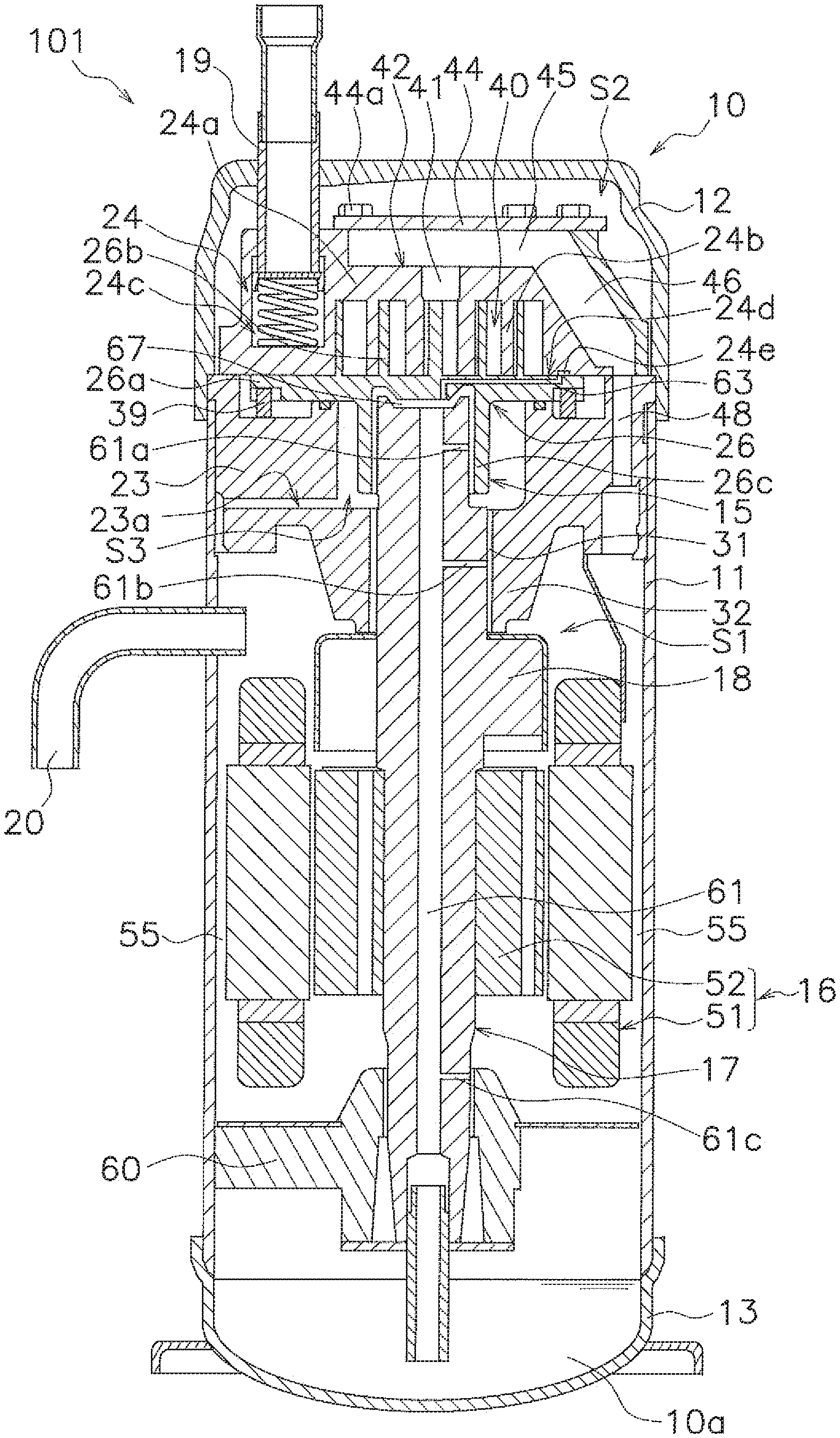
[0029] FIG. 1 is a longitudinal sectional view of a scroll compressor pertaining to an embodiment.
[0030] FIG. 2 is a bottom view of a fixed scroll.
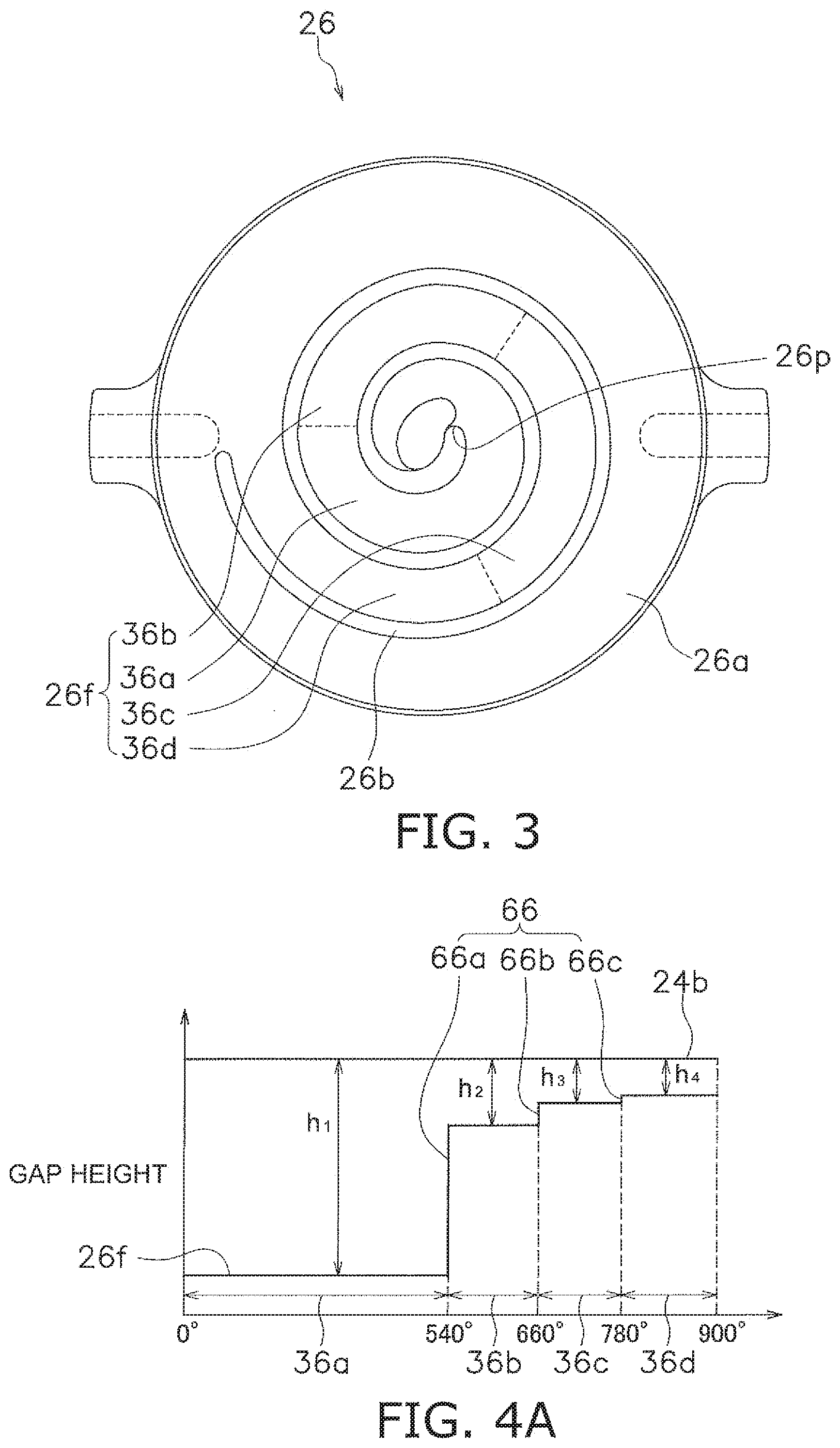
[0031] FIG. 3 is a top view of an orbiting scroll.
[0032] FIG. 4A is a drawing describing a first gap that is a gap between a first wrap and a second end plate.
[0033] FIG. 4B is a drawing describing a second gap that is a gap between a first end plate and a second wrap.
[0034] FIG. 5A is a drawing describing a change in the height of the first gap.
[0035] FIG. 5B is a drawing describing a change in the height of the second gap.
DESCRIPTION OF EMBODIMENT
[0036] An embodiment of the invention will be described below. It will be noted that the following embodiment is merely a concrete example and is not intended to limit the invention pertaining to the scope of the claims.
First Embodiment
[0037] FIG. 1 is a longitudinal sectional view of a scroll compressor 101 pertaining to the embodiment. The scroll compressor 101 is used in a refrigerating system such as an air conditioning system. The scroll compressor 101 compresses refrigerant gas that circulates through a refrigerant circuit of the refrigerating system. As the refrigerant, refrigerant that includes more than 50 wt % R32 can be used.
(1) Configuration of Scroll Compressor
[0038] The scroll compressor 101 mainly has a casing 10, a compression mechanism 15, a housing 23, an Oldham coupling 39, a drive motor 16, a lower bearing 60, a crankshaft 17, a suction pipe 19, and a discharge pipe 20.
(1-1) Casing
[0039] The casing 10 is configured from a middle casing portion 11 in the shape of an open cylinder, an upper wall portion 12 in the shape of a bowl, and a bottom wall portion 13 in the shape of a bowl. The upper wall portion 12 is airtightly welded to the upper end portion of the middle casing portion 11. The bottom wall portion 13 is airtightly welded to the lower end portion of the middle casing portion 11. The casing 10 is installed in such a way that the axial direction of the open cylinder shape of the middle casing portion 11 lies along the vertical direction.
[0040] Inside the casing 10 are housed the compression mechanism 15, the housing 23, the drive motor 16, the crankshaft 17, and the like. In the bottom portion of the casing 10 is formed an oil reservoir 10a in which lubricating oil is stored. The lubricating oil is used to well maintain the lubricity of sliding portions of the compression mechanism 15 and the like during the operation of the scroll compressor 101.
(1-2) Compression Mechanism
[0041] The compression mechanism 15 sucks and compresses low-temperature low-pressure refrigerant gas and discharges compressed refrigerant that is high-temperature high-pressure refrigerant gas. The compression mechanism 15 is configured mainly from a fixed scroll 24 and an orbiting scroll 26. The fixed scroll 24 is fixed with respect to the casing 10. The orbiting scroll 26 performs revolving movement with respect to the fixed scroll 24.
(1-2-1) Fixed Scroll
[0042] The fixed scroll 24 has a first end plate 24a serving as a first base and a first wrap 24b. The first wrap 24b is formed upright on the first end plate 24a. The first wrap 24b is spiral in shape. The height of the first wrap 24b is preferably 20 to 40 mm. The number of turns of the first wrap 24b is longer than the number of turns of a later-described second wrap 26b. Specifically, it is about 1/2 turn longer. An outer peripheral surface is not formed on the outermost periphery of the first wrap 24b. The outermost periphery of the first wrap 24b is continuous with the edge portion of the fixed scroll 24. A main suction hole 24c is formed in the first end plate 24a. The main suction hole 24c is a space that interconnects the suction pipe 19 and a later-described compression chamber 40. The main suction hole 24c forms a suction space. The suction space is a space for introducing the low-temperature low-pressure refrigerant gas from the suction pipe 19 to the compression chamber 40.
[0043] A discharge hole 41 is formed in the central portion of the first end plate 24a. An enlarged recess portion 42 that communicates with the discharge hole 41 is formed in the upper surface of the first end plate 24a. The enlarged recess portion 42 is a space that is recessedly provided in the upper surface of the first end plate 24a. A cover 44 is fixed by bolts 44a to the upper surface of the fixed scroll 24 so as to close off the enlarged recessed portion 42. The fixed scroll 24 and the cover 44 are tightly sealed via a gasket (not shown in the drawings). A muffler space 45 that muffles the operating sound of the compression mechanism 15 is formed as a result of the enlarged recessed portion 42 being covered with the cover 44. A first compressed refrigerant flow passage 46 that communicates with the muffler space 45 and opens to the lower surface of the fixed scroll 24 is formed in the fixed scroll 24. An oil groove 24e is formed in the lower surface of the first end plate 24a.
(1-2-2) Orbiting Scroll
[0044] The orbiting scroll 26 has a second end plate 26a serving as a second base and a second wrap 26b. The second end plate 26a is in the shape of a disc. An upper end bearing 26c is formed in the central portion of the lower surface of the second end plate 26a. The second wrap 26b is formed upright on the second end plate 26a. The second wrap 26b is spiral in shape. The height of the second wrap 26b is preferably 20 to 40 mm. An oil supply pore 63 is formed in the orbiting scroll 26. The oil supply pore 63 communicates the outer peripheral portion of the upper surface of the second end plate 26a to the space inside the upper end bearing 26c.
[0045] The first wrap 24b and the second wrap 26b interfit, whereby the fixed scroll 24 and the orbiting scroll 26 form a compression chamber 40. The compression chamber 40 is a space enclosed by the first end plate 24a, the first wrap 24b, the second end plate 26a, and the second wrap 26b. The volume of the compression chamber 40 gradually decreases because of the revolving movement of the orbiting scroll 26. As the orbiting scroll 26 revolves, the lower surface of the first end plate 24a and the first wrap 24b of the fixed scroll 24 slides against the upper surface of the second end plate 26a and the second wrap 26b of the orbiting scroll 26. In this specification, the surface of the fixed scroll 24 that slides against the orbiting scroll 26 is called a sliding surface 24d.
[0046] Although details will be described later, a first gap is formed between the distal end of the first wrap 24b (i.e., the portion of the first wrap 24b that opposes the second end plate 26a) and the second end plate 26a. A second gap is formed between the distal end of the second wrap 26b (i.e., the portion of the second wrap 26b that opposes the first end plate 24a) and the first end plate 24a. In the present embodiment, both a first condition and a second condition described below are satisfied in relation to the first gap and the second gap.
[0047] The first condition is a condition where the first gap changes heading from the outer peripheral side of the first wrap 24b to the inner peripheral side and where the rate of change in the first gap in a range from a center 24p (see FIG. 2) of the first wrap 24b to an intermediate point of the first wrap 24b is greater than the rate of change in the first gap in a range from the intermediate point of the first wrap 24b to the outer peripheral end of the first wrap 24b. In the present embodiment, the range from the center 24p of the first wrap 24b to the intermediate point of the first wrap 24b is a range from the center 24p of the first wrap 24b to 540.degree.. The range from the intermediate point of the first wrap 24b to the outer peripheral end of the first wrap 24b is a range from 540.degree. of the first wrap 24b to 1080.degree..
[0048] Although details will be described later, the rate of change in the first gap in the range from the center 24p of the first wrap 24b to 540.degree. is a value obtained by dividing the amount of change in the height of the first gap in the range from the center 24p of the first wrap 24b to 540.degree. by the number of steps included in the portion of the second end plate 26a corresponding to the range from the center 24p of the first wrap 24b to 540.degree.. The rate of change in the first gap in the range from 540.degree. of the first wrap 24b to 1080.degree. is a value obtained by dividing the amount of change in the height of the first gap in the range from 540.degree. of the first wrap 24b to 1080.degree. by the number of steps included in the portion of the second end plate 26a corresponding to the range from 540.degree. of the first wrap 24b # to 1080.degree..
[0049] The second condition is a condition where the second gap changes heading from the outer peripheral side of the second wrap 26b to the inner peripheral side and where the rate of change in the second gap in a range from a center 26p (see FIG. 3) of the second wrap 26b to an intermediate point of the second wrap 26b is greater than the rate of change in the second gap in a range from the intermediate point of the second wrap 26b to the outer peripheral end of the second wrap 26b. In the present embodiment, the range from the center 26p of the second wrap 26b to the intermediate point of the second wrap 26b is a range from the center 26p of the second wrap 24b to 540.degree.. The range from the intermediate point of the second wrap 26b to the outer peripheral end of the second wrap 26b is a range from 540.degree. to 900.degree. of the second wrap 26b.
[0050] Although details will be described later, the rate of change in the second gap in the range from the center 26p of the second wrap 26b to 540.degree. is a value obtained by dividing the amount of change in the height of the second gap in the range from the center 26p of the second wrap 26b to 540.degree. by the number of steps included in the portion of the first end plate 24a corresponding to the range from the center 26p of the second wrap 26b to 540.degree.. The rate of change in the second gap in the range from 540.degree. of the second wrap 26b to 900.degree. is a value obtained by dividing the amount of change in the height of the second gap in the range from 540.degree. of the second wrap 26b to 900.degree. by the number of steps included in the portion of the first end plate 24a corresponding to the range from 540.degree. of the second wrap 26b # to 900.degree..
(1-3) Housing
[0051] The housing 23 is disposed under the compression mechanism 15. The outer peripheral surface of the housing 23 is airtightly joined to the inner peripheral surface of the middle casing portion 11. Because of this, the inside space of the casing 10 is partitioned into a high-pressure space S1 under the housing 23 and a low-pressure space S2 that is a space above the housing 23. The housing 23 has the fixed scroll 24 mounted on it and, together with the fixed scroll 24, sandwiches the orbiting scroll 26. A second compressed refrigerant flow passage 48 is formed in, so as to run in the vertical direction through, the outer peripheral portion of the housing 23. The second compressed refrigerant flow passage 48 communicates with the first compressed refrigerant flow passage 46 at the upper surface of the housing 23 and communicates with the high-pressure space S1 at the lower surface of the housing 23.
[0052] A crank chamber S3 is recessedly provided in the upper surface of the housing 23. A housing through hole 31 is formed in the housing 23. The housing through hole 31 runs in the vertical direction through the housing 23 from the central portion of the bottom surface of the crank chamber S3 to the central portion of the lower surface of the housing 23. In this specification, the part of the housing 23 that has the housing through hole 31 formed in it is called an upper bearing 32. In the housing 23 is formed an oil return passageway 23a that communicates the high-pressure space S1 in the neighborhood of the inner surface of the casing 10 to the crank chamber S3.
(1-4) Oldham Coupling
[0053] The Oldham coupling 39 is an annular member installed between the orbiting scroll 26 and the housing 23. The Oldham coupling 39 is a member for preventing self-rotation of the revolving orbiting scroll 26.
(1-5) Drive Motor
[0054] The drive motor 16 is a brushless DC motor disposed under the housing 23. The drive motor 16 is configured mainly from a stator 51 fixed to the inner surface of the casing 10 and a rotor 52 disposed inside the stator 51 with an air gap between them.
[0055] In the outer peripheral surface of the stator 51 are provided plural core cut portions comprising cutouts formed a predetermined interval apart from each other in the circumferential direction and ranging from the upper end surface of the stator 51 to the lower end surface. The core cut portions form motor cooling passageways 55 that extend in the vertical direction between the middle casing portion 11 and the stator 51.
[0056] The rotor 52 is coupled to the crankshaft 17, which runs in the vertical direction through the rotational center of the rotor 52. The rotor 52 is connected via the crankshaft 17 to the compression mechanism 15.
(1-6) Lower Bearing
[0057] The lower bearing 60 is disposed under the drive motor 16. The outer peripheral surface of the lower bearing 60 is airtightly joined to the inner surface of the casing 10. The lower bearing 60 supports the crankshaft 17.
(1-7) Crankshaft
[0058] The crankshaft 17 is disposed in such a way that its axial direction lies along the vertical direction. The crankshaft 17 has a shape in which the axial center of the upper end portion of the crankshaft 17 is slightly eccentric with respect to the axial center of the portion excluding the upper end portion. The crankshaft 17 has a counterweight 18. The counterweight 18 is tightly fixed to the crankshaft 17 at a height position under the housing 23 and above the drive motor 16.
[0059] The crankshaft 17 runs in the vertical direction through the rotational center of the rotor 52 and is coupled to the rotor 52. The upper end portion of the crankshaft 17 is fitted into the upper end bearing 26c, whereby the crankshaft 17 is connected to the orbiting scroll 26. The crankshaft 17 is supported by the upper bearing 32 and the lower bearing 60.
[0060] The crankshaft 17 has inside a main oil supply passage 61 that extends in the axial direction of the crankshaft 17. The upper end of the main oil supply passage 61 communicates with an oil chamber 67 formed by the upper end surface of the crankshaft 17 and the lower surface of the second end plate 26a. The oil chamber 67 communicates with the sliding surface 24d and the oil groove 24e via the oil supply pore 63 in the second end plate 26a and finally communicates with the low-pressure space S2 via the compression chamber 40. The lower end of the main oil supply passage 61 is connected to an oil supply pipe that is a pipe for supplying to the compression mechanism 15 the lubricating oil stored in the oil reservoir 10a.
[0061] The crankshaft 17 has a first auxiliary oil supply passage 61a, a second auxiliary oil supply passage 61b, and a third auxiliary oil supply passage 61c that branch from the main oil supply passage 61. The first auxiliary oil supply passage 61a, the second auxiliary oil supply passage 61b, and the third auxiliary oil supply passage 61c extend in the horizontal direction. The first auxiliary oil supply passage 61a opens to the sliding surfaces of the crankshaft 17 and the upper end bearing 26c of the orbiting scroll 26. The second auxiliary oil supply passage 61b opens to the sliding surfaces of the crankshaft 17 and the upper bearing 32 of the housing 23. The third auxiliary oil supply passage 61c opens to the sliding surfaces of the crankshaft 17 and the lower bearing 60.
(1-8) Suction Pipe
[0062] The suction pipe 19 is a pipe for introducing the refrigerant in the refrigerant circuit from the outside of the casing 10 to the compression mechanism 15. The suction pipe 19 is airtightly fitted into the upper wall portion 12 of the casing 10. The suction pipe 19 runs in the vertical direction through the low-pressure space S2.
(1-9) Discharge Pipe
[0063] The discharge pipe 20 is a pipe for discharging the compressed refrigerant from the high-pressure space S1 to the outside of the casing 10. The discharge pipe 20 is airtightly fitted into the middle casing portion 11 of the casing 10. The discharge pipe 20 runs in the horizontal direction through the high-pressure space S1.
(2) Details of Fixed Scroll and Orbiting Scroll
[0064] FIG. 2 is a bottom view of the fixed scroll 24 seen along the vertical direction. Plural regions are formed in a refrigerant flow passage portion 24f of the fixed scroll 24 from the main suction hole 24c to the discharge hole 41. In the present embodiment, four regions are formed. Namely, a first region 34a, a second region 34b, a third region 34c, and a fourth region 34d are formed.
[0065] The first region 34a is a region on the innermost peripheral side of the refrigerant flow passage portion 24f. In the present embodiment, the first region 34a is a region corresponding to a range from the center 24p of the first wrap 24b (i.e., the start of the spiral) to 540.degree.. In the present embodiment, the range from the center 24p of the first wrap 24b to 540.degree. is defined as the center portion of the first wrap 24b, and the first region 34a is defined as the center portion of the first end plate 24a. The center portions of the first wrap 24b and the first end plate 24a form a center portion of the compression chamber 40.
[0066] The second region 34b is a region continuous with the first region 34a. The second region 34b is a region between the first region 34a and the third region 34c. In the present embodiment, the second region 34b is a region corresponding to a range from 540.degree. of the first wrap 24b to 720.degree..
[0067] The third region 34c is a region continuous with the second region 34b. The third region 34c is a region between the second region 34b and the fourth region 34d. In the present embodiment, the third region 34c is a region corresponding to a range from 720.degree. of the first wrap 24b to 900.degree..
[0068] The fourth region 34d is a region continuous with the third region 34c. The fourth region 34d is a region on the outermost peripheral side of the refrigerant flow passage portion 24f. In the present embodiment, the fourth region 34d is a region corresponding to a range from 900.degree. of the first wrap 24b to the outer peripheral end (1080.degree.).
[0069] In the present embodiment, the range from 540.degree. of the first wrap 24b to the outer peripheral end is defined as the non-center portion of the first wrap 24b, and the second region 34b, the third region 34c, and the fourth region 34d are defined as the non-center portion of the first end plate 24a. The non-center portions of the first wrap 24b and the first end plate 24a form a non-center portion of the compression chamber 40.
[0070] FIG. 3 is a top view of the orbiting scroll 26 seen along the vertical direction. Plural regions are formed in a refrigerant flow passage portion 26f of the orbiting scroll 26 surrounded from the center 26p of the second wrap 26b to the outer peripheral end. In the present embodiment, four regions are formed. Namely, a first region 36a, a second region 36b, a third region 36c, and a fourth region 36d are formed.
[0071] The first region 36a is a region on the innermost peripheral side of the refrigerant flow passage portion 26f. In the present embodiment, the first region 36a is a region corresponding to a range from the center 26p of the second wrap 26b (i.e., the start of the spiral) to 540.degree.. In the present embodiment, the range from the center 26p of the second wrap 26b to 540.degree. is defined as the center portion of the second wrap 26b, and the first region 36a is defined as the center portion of the second end plate 26a. The center portions of the second wrap 26b and the second end plate 26a form the center portion of the compression chamber 40.
[0072] The second region 36b is a region continuous with the first region 36a. The second region 36b is a region between the first region 36a and the third region 36c. In the present embodiment, the second region 36b is a region corresponding to a range from 540.degree. of the second wrap 26b to 660.degree..
[0073] The third region 36c is a region continuous with the second region 36b. The third region 36c is a region between the second region 36b and the fourth region 36d. In the present embodiment, the third region 36c is a region corresponding to a range from 660.degree. of the second wrap 26b to 780.degree..
[0074] The fourth region 36d is a region continuous with the third region 36c. The fourth region 36d is a region on the outermost peripheral side of the refrigerant flow passage portion 26f. In the present embodiment, the fourth region 36d is a region corresponding to a range from 780.degree. of the second wrap 26b to the outer peripheral end (900.degree.).
[0075] In the present embodiment, the range from 540.degree. of the second wrap 26b to the outer peripheral end is defined as the non-center portion of the second wrap 26b, and the second region 36b, the third region 36c, and the fourth region 36d are defined as the non-center portion of the second end plate 26a. The non-center portions of the second wrap 26b and the second end plate 26a form the non-center portion of the compression chamber 40.
[0076] FIG. 4A is a drawing describing the first gap that is a gap between the first wrap 24b and the second end plate 26a. In FIG. 4A, the horizontal axis represents the angle from the center 26p of the second wrap 26b. The vertical axis represents the height of the first gap. Namely, the vertical axis represents the distance between the distal end of the first wrap 24b and the second end plate 26a (particularly the refrigerant flow passage portion 26f). Gap height h.sub.1 represents the distance between the distal end of the first wrap 24b and the first region 36a. Gap height h.sub.2 represents the distance between the distal end of the first wrap 24b and the second region 36b. Gap height h.sub.3 represents the distance between the distal end of the first wrap 24b and the third region 36c. Gap height h.sub.4 represents the distance between the distal end of the first wrap 24b and the fourth region 36d.
[0077] As shown in FIG. 4A, the height of the refrigerant flow passage portion 26f changes heading from the outer peripheral side to the inner peripheral side. The height of the refrigerant flow passage portion 26f becomes lower heading from the outer peripheral side to the inner peripheral side. Namely, the thickness of the refrigerant flow passage portion 26f becomes thinner. In the present embodiment, the height of the refrigerant flow passage portion 26f becomes lower in a stepwise manner heading from the outer peripheral side toward the inner peripheral side. More specifically, the height of the refrigerant flow passage portion 26f becomes lower in the order of the fourth region 36d, the third region 36c, the second region 36b, and the first region 36a.
[0078] Three step portions 66 are formed in the refrigerant flow passage portion 26f as a result of the refrigerant flow passage portion 26f becoming lower in a stepwise manner. Namely, a step portion 66a is formed at the boundary between the second region 36b and the first region 36a, a step portion 66b is formed at the boundary between the third region 36c and the second region 36b, and a step portion 66c is formed at the boundary between the fourth region 36d and the third region 36c.
[0079] In contrast, the height of the first wrap 24b is constant. As a result, the height of the first gap changes heading from the outer peripheral side of the first wrap 24b to the inner peripheral side. The height of the first gap becomes wider heading from the outer peripheral side of the first wrap 24b to the inner peripheral side. The height of the first gap changes in a stepwise manner. Gap height h.sub.1 is the largest, and gap height h.sub.4 is the smallest.
[0080] As described above, the height of the refrigerant flow passage portion 26f changes, while the height of the first wrap 24b is constant. Consequently, the amount of change in the height of the refrigerant flow passage portion 26f can be understood as the amount of change in the first gap itself.
[0081] In the present embodiment, the center portion of the second end plate 26a includes the step portion 66a. Consequently, the gap heights at the outer peripheral end (i.e., the step portion 66a) and the inner peripheral end of the center portion of the second end plate 26a differ. Specifically, they differ by the difference between gap height h.sub.1 and gap height h.sub.2. The height of the step portion 66a is h.sub.1-h.sub.2.
[0082] In the present embodiment, the non-center portion of the second end plate 26a includes two step portions. Namely, the non-center portion of the second end plate 26a includes the step portion 66b and the step portion 66c. The height of the step portion 66b is h.sub.2-h.sub.3, and the height of the step portion 66c is h.sub.3-h.sub.4.
[0083] FIG. 4B is a drawing describing the second gap that is a gap between the first end plate 24a and the second wrap 26b. In FIG. 4B, the horizontal axis represents the angle from the center 24p of the first wrap 24b. The vertical axis represents the height of the second gap. Namely, the vertical axis represents the distance between the first end plate 24a (particularly the refrigerant flow passage portion 24f) and the distal end of the second wrap 26b. Gap height h.sub.5 represents the distance between the distal end of the second wrap 26b and the first region 34a. Gap height h.sub.6 represents the distance between the distal end of the second wrap 26b and the second region 34b. Gap height h.sub.7 represents the distance between the distal end of the second wrap 26b and the third region 34c. Gap height h.sub.8 represents the distance between the distal end of the second wrap 26b and the fourth region 34d.
[0084] As shown in FIG. 4B, the height of the refrigerant flow passage portion 24f changes heading from the outer peripheral side to the inner peripheral side. The height of the refrigerant flow passage portion 24f becomes lower heading from the outer peripheral side toward the inner peripheral side. Namely, the thickness of the refrigerant flow passage portion 24f becomes thinner. In the present embodiment, the height of the refrigerant flow passage portion 24f becomes lower in a stepwise manner heading from the outer peripheral side toward the inner peripheral side. More specifically, the height of the refrigerant flow passage portion 24f becomes lower in the order of the fourth region 34d, the third region 34c, the second region 34b, and the first region 34a.
[0085] Three step portions 64 are formed in the refrigerant flow passage portion 24f as a result of the refrigerant flow passage portion 24f becoming lower in a stepwise manner. Namely, a step portion 64a is formed at the boundary between the second region 34b and the first region 34a, a step portion 64b is formed at the boundary between the third region 34c and the second region 34b, and a step portion 64c is formed at the boundary between the fourth region 34d and the third region 34c.
[0086] In contrast, the height of the second wrap 26b is constant. As a result, the height of the second gap changes heading from the outer peripheral side to the inner peripheral side of the second wrap 26b. The height of the second gap becomes wider heading from the outer peripheral side to the inner peripheral side of the second wrap 26b. The height of the second gap changes in a stepwise manner. Gap height h.sub.5 is the largest, and gap height h.sub.8 is the smallest.
[0087] As described above, the height of the refrigerant flow passage portion 24f changes, while the height of the second wrap 26b is constant. Consequently, the amount of change in the height of the refrigerant flow passage portion 24f can be understood as the amount of change in the second gap itself.
[0088] In the present embodiment, the center portion of the first end plate 24a includes the step portion 64a. Consequently, the gap heights at the outer peripheral end (i.e., the step portion 64a) and the inner peripheral end of the center portion of the first end plate 24a differ. Specifically, they differ by the difference between gap height h.sub.5 and gap height h.sub.6. The height of the step portion 64a is h.sub.5-h.sub.6.
[0089] In the present embodiment, the non-center portion of the first end plate 24a includes two step portions. Namely, the non-center portion of the first end plate 24a includes the step portion 64b and the step portion 64c. The height of the step portion 64b is h.sub.6-h.sub.7, and the height of the step portion 64c is h.sub.7-h.sub.8.
[0090] FIG. 5A is a drawing describing the change in the height of the first gap. In FIG. 5A, the horizontal axis represents the angle of the second wrap 26b, and the vertical axis represents the height of the first gap. Here, gap height h.sub.4 is defined as a reference for the gap height. Furthermore, as an example, the height of the step portion 66c is defined as 1 .mu.m, the height of the step portion 66b is defined as 9 .mu.m, and the height of the step portion 66a is defined as 26 .mu.m. In that case, gap height h.sub.3 can be expressed as h.sub.4+1, gap height h.sub.2 can be expressed as h.sub.4+10, and gap height h.sub.1 can be expressed as h.sub.4+36.
[0091] In the present embodiment, the amount of change at the center portion of the second end plate 26a is h.sub.1-h.sub.2=26 .mu.m. The number of steps in the center portion of the second end plate 26a is 1, so the rate of change at the center portion of the second end plate 26a is 26. The amount of change at the non-center portion of the second end plate 26a is h.sub.2-h.sub.4=10 .mu.m. The number of steps in the non-center portion of the second end plate 26a is 2, so the rate of change at the non-center portion of the second end plate 26a (the average of the amount of change per step) is 10/2=5.
[0092] As described above, the rate of change in the first gap at the center portion of the second end plate 26a is greater than the rate of change in the first gap at the non-center portion of the second end plate 26a. More specifically, the rate of change in the first gap at the center portion of the second end plate 26a is 5.2 times the rate of change in the first gap at the non-center portion of the second end plate 26a. The first gap becomes locally larger in the range of the center portion of the second end plate 26a. It will be noted that preferably the rate of change in the first gap at the center portion of the second end plate 26a is in the range of 4.5 times to 5.5 times the rate of change in the first gap at the non-center portion of the second end plate 26a.
[0093] FIG. 5B is a drawing describing the change in the height of the second gap. In FIG. 5B, the horizontal axis represents the angle of the first wrap 24b, and the vertical axis represents the height of the second gap. Here, gap height h.sub.8 is defined as a reference for the gap height. Furthermore, as an example, the height of the step portion 64c is defined as 1 .mu.m, the height of the step portion 64b is defined as 9 .mu.m, and the height of the step portion 64a is defined as 26 .mu.m. In that case, gap height h.sub.7 can be expressed as h.sub.8+1, gap height h.sub.6 can be expressed as h.sub.8+10, and gap height h.sub.5 can be expressed as h.sub.8+36.
[0094] In the present embodiment, the amount of change at the center portion of the first end plate 24a is h.sub.5-h.sub.6=26 .mu.m. The number of steps in the center portion of the first end plate 24a is 1, so the rate of change at the center portion of the first end plate 24a is 26. The amount of change at the non-center portion of the first end plate 24a is h.sub.6-h.sub.8=10 .mu.m. The number of steps in the non-center portion of the first end plate 24a is 2, so the rate of change at the non-center portion of the first end plate 24a (the average of the amount of change per step) is 10/2=5.
[0095] As described above, the rate of change in the second gap at the center portion of the first end plate 24a is greater than the rate of change in the second gap at the non-center portion of the first end plate 24a. More specifically, the rate of change in the second gap at the center portion of the first end plate 24a is 5.2 times the rate of change in the second gap at the non-center portion of the first end plate 24a. The second gap becomes locally larger in the range of the center portion of the first end plate 24a. It will be noted that preferably the rate of change in the second gap at the center portion of the first end plate 24a is in the range of 4.5 times to 5.5 times the rate of change in the second gap at the non-center portion of the first end plate 24a.
(3) Operation of Scroll Compressor
[0096] First, the rotor 52 is rotated by the driving of the drive motor 16. Because of this, the crankshaft 17 fixed to the rotor 52 rotates. The rotational movement of the crankshaft 17 is transmitted via the upper end bearing 26c to the orbiting scroll 26. The axial center of the upper end portion of the crankshaft 17 is eccentric with respect to the axis of the rotational movement of the crankshaft 17. The orbiting scroll 26 is engaged with the housing 23 via the Oldham coupling 39. Because of this, the orbiting scroll 26 performs revolving movement with respect to the fixed scroll 24 without self-rotating.
[0097] The low-temperature low-pressure refrigerant before being compressed is supplied from the suction pipe 19 via the main suction hole 24c to the compression chamber 40 of the compression mechanism 15. Because of the revolving movement of the orbiting scroll 26, the compression chamber 40 moves from the outer peripheral portion of the fixed scroll 24 to the center portion while its volume is gradually decreased. As a result, the refrigerant in the compression chamber 40 is compressed and becomes compressed refrigerant. When the compression chamber 40 moves from the outer peripheral portion of the fixed scroll 24 # to the center portion, the temperature of the compression chamber 40 rises in accompaniment with the move. Particularly in a case where the refrigerant is compressed in a high-load condition, the temperature rises more. In accompaniment with the rise in temperature, the fixed scroll 24 and the orbiting scroll 26 expand.
[0098] Here, in the scroll compressor 101 of the present embodiment, the first gap and the second gap are locally large at the center portion of the compression chamber 40, which is more susceptible to the effects of heat. Consequently, even if the fixed scroll 24 and the orbiting scroll 26 expand due to heat, contact between the fixed scroll 24 and the orbiting scroll 26 can be inhibited.
[0099] The compressed refrigerant is discharged from the discharge hole 41 to the muffler space 45 and thereafter is discharged via the first compressed refrigerant flow passage 46 and the second compressed refrigerant flow passage 48 to the high-pressure space S1. Then, the compressed refrigerant descends through the motor cooling passageways 55 and reaches the high-pressure space S1 under the drive motor 16. Then, the compressed refrigerant reverses its flow direction and ascends through other motor cooling passageways 55 and the air gap in the drive motor 16. Finally, the compressed refrigerant is discharged from the discharge pipe 20 to the outside of the scroll compressor 101.
(4) Characteristics of Scroll Compressor
[0100] In the scroll compressor 101 of the present embodiment, the rate of change in the first gap at the center portion of the second end plate 26a is greater than the rate of change in the first gap at the non-center portion of the second end plate 26a. The first gap in the range of the center portion of the second end plate 26a becomes locally larger. Consequently, in the center portion of the second end plate 26a, contact between the distal end of the first wrap 24b and the second end plate 26a can be inhibited. The first gap at the center portion of the first wrap 24b is set to become locally larger in anticipation of the expansion of the first wrap 24b due to heat at the center portion of the compression chamber 40, which can reach a particularly high temperature, so contact between the fixed scroll 24 and the orbiting scroll 26 at the center portion of the compression chamber 40 can be inhibited.
[0101] In the same way, the rate of change in the second gap at the center portion of the first end plate 24a is greater than the rate of change in the second gap at the non-center portion of the first end plate 24a. The second gap in the range of the center portion of the first end plate 24a becomes locally larger. Consequently, at the center portion of the first end plate 24a, contact between the distal end of the second wrap 26b and the first end plate 24a can be inhibited. The second gap at the center portion of the second wrap 26b is set to become locally larger in anticipation of the expansion of the second wrap 26b due to heat # at the center portion of the compression chamber 40, which can reach a particularly high temperature, so contact between the fixed scroll 24 and the orbiting scroll 26 at the center portion of the compression chamber 40 can be inhibited.
[0102] In the scroll compressor 101 of the present embodiment, the first gap changes in a stepwise manner heading from the outer peripheral side of the first wrap 24b # to the inner peripheral side. The second gap changes in a stepwise manner heading from the outer peripheral side of the second wrap 26b # to the inner peripheral side. The first gap and the second gap gradually change heading toward the center portion of the compression chamber 40, so contact between the fixed scroll 24 and the orbiting scroll 26 can be effectively inhibited.
[0103] In the scroll compressor 101 of the present embodiment, the second end plate 26a includes the step portion 66a in the range of the center portion of the first wrap 24b, and the first end plate 24a includes the step portion 64a in the range of the center portion of the second wrap 26b. Because of the step portion 66a, the first gap at the center portion of the second end plate 26a can easily be made locally larger. In the same way, because of the step portion 64a, the second gap at the center portion of the first end plate 24a can easily be made locally larger.
[0104] In the scroll compressor 101 of the present embodiment, the second end plate 26a is formed in a stepwise manner, whereby the first gap changes in a stepwise manner heading from the outer peripheral side of the first wrap 24b # to the inner peripheral side. The first end plate 24a is formed in a stepwise manner, whereby the second gap changes in a stepwise manner heading from the outer peripheral side of the second wrap 26b # to the inner peripheral side. Thus, compared to a case where the second end plate 26a and the first end plate 24a are formed in a sloping manner, processing for forming the first gap and the second gap becomes easy.
[0105] In the scroll compressor 101 of the present embodiment, the center portion of the first wrap 24b is a range from the center of the first wrap 24b to 540.degree.. The center portion of the second wrap 26b is a range from the center of the second wrap 26b to 540.degree.. The first gap in the range from the center of the first wrap 24b to 540.degree. and the second gap in the range from the center of the second wrap 26b to 540.degree., which can reach a particularly high temperature, are made locally larger, so contact between the fixed scroll 24 and the orbiting scroll 26 can be effectively inhibited.
[0106] In the scroll compressor 101 of the present embodiment, the rate of change in the first gap at the center portion of the second end plate 26a is in the range of 4.5 times to 5.5 times the rate of change in the first gap at the non-center portion of the second end plate 26a. The rate of change in the second gap at the center portion of the first end plate 24a is in the range of 4.5 times to 5.5 times the rate of change in the second gap at the non-center portion of the first end plate 24a. Because of the above, contact between the fixed scroll 24 and the orbiting scroll 26 can be effectively inhibited.
[0107] In the scroll compressor 101 of the present embodiment, the fixed scroll 24 and the orbiting scroll 26 compress refrigerant that includes more than 50 wt % R32 as refrigerant. When R410A refrigerant and refrigerant that includes more than 50 wt % R32 are compressed under the same conditions, the refrigerant that includes more than 50 wt % R32 reaches a higher temperature than the R410A refrigerant. That is, it becomes easier for the first wrap 24b and the second wrap 26b to deform. Even in a case such as this, the scroll compressor 101 satisfies the first condition and the second condition, so contact between the fixed scroll 24 and the orbiting scroll 26 can be inhibited.
EXAMPLE MODIFICATIONS
[0108] Example modifications applicable to the embodiment of the invention will be described.
(1) Example Modification A
[0109] In the above description, the second end plate 26a is formed in a stepwise manner, but the configuration whereby the first gap changes in a stepwise manner heading from the outer peripheral side of the first wrap 24b to the inner peripheral side is not limited to this. The first wrap 24b may also be formed in a stepwise manner, or the first wrap 24b and the second end plate 26a may also be formed in a stepwise manner. Namely, it suffices for at least one of the first wrap 24b and the second end plate 26a to be formed in a stepwise manner. It suffices for at least one of the first wrap 24b and the second end plate 26a to include a step portion in the range of the center portion of the first wrap 24b.
[0110] In the same way, in the above description, the first end plate 24a is formed in a stepwise manner, but the configuration whereby the second gap changes in a stepwise manner heading from the outer peripheral side of the second wrap 26b to the inner peripheral side is not limited to this. The second wrap 26b may also be formed in a stepwise manner, or the second wrap 26b and the first end plate 24a may also be formed in a stepwise manner. Namely, it suffices for at least one of the second wrap 26b and the first end plate 24a to be formed in a stepwise manner. It suffices for at least one of the second wrap 26b and the first end plate 24a to include a step portion in the range of the center portion of the second wrap 26b.
(2) Example Modification B
[0111] In the above description, three step portions are formed in each of the refrigerant flow passage portion 24f and the refrigerant flow passage portion 26f, but two step portions may also be formed, or four or more step portions may also be formed.
(3) Example Modification C
[0112] In the above description, the center portion of the first end plate 24a is a range from the center of the first wrap 24b to 540.degree., but the range of the center portion of the first end plate 24a is not limited to this. The range of the center portion of the first end plate 24a may also change in accordance with the number of step portions. For example, in a case where four step portions are formed in the refrigerant flow passage portion 24f, the center portion of the first end plate 24a may also be a range from the center of the first wrap 24b to 360.degree..
[0113] In the same way, the center portion of the second end plate 26a is a range from the center of the second wrap 26b to 540.degree., but the range of the center portion of the second end plate 26a is not limited to this. The range of the center portion of the second end plate 26a may also change in accordance with the number of step portions. For example, in a case where four step portions are formed in the refrigerant flow passage portion 26f, the center portion of the second end plate 26a may also be a range from the center of the second wrap 26b to 360.degree..
(4) Example Modification D
[0114] In the above description, the center portion of the first end plate 24a and the center portion of the second end plate 26a each have one step portion, but the configuration of the center portion of the first end plate 24a and the center portion of the second end plate 26a is not limited to this. The center portion of the first end plate 24a and the center portion of the second end plate 26a may also each have two or more step portions. Namely, it suffices for the center portion of the first end plate 24a and the center portion of the second end plate 26a to each include at least one step portion.
(5) Example Modification E
[0115] In the above description, the first gap and the second gap change in a stepwise manner, but the configuration of the first gap and the second gap is not limited to changing in a stepwise manner. The first gap and the second gap may also change in a sloping manner.
(6) Example Modification F
[0116] In the above description, the scroll compressor 101 satisfies both the first condition and the second condition, but the scroll compressor 101 may also satisfy just the first condition or may also satisfy just the second condition. Namely, it suffices for the scroll compressor 101 to satisfy at least one of the first condition and the second condition. More specifically, just the first gap at the center portion of the compression chamber 40 may become locally larger, or just the second gap at the center portion of the compression chamber 40 may become locally larger. Namely, it suffices for the gap at the center portion of the compression chamber 40 to become locally larger in at least one of the first gap and the second gap. By satisfying at least one of the first condition and the second condition, contact between the fixed scroll 24 and the orbiting scroll 26 can be inhibited.
(7) Example Modification G
[0117] In the above description, the change in the height of the first gap is the same as the change in the height of the second gap, but the change in the height of the first gap may also be different from the change in the height of the second gap.
[0118] The invention has been described above using an embodiment, but the technical scope of the invention is not limited to the scope described in the above embodiment. It will be apparent to persons skilled in the art that various changes or improvements can be made to the above embodiment. That embodiments to which such changes or improvements have been made can also be included in the technical scope of the invention will be apparent from the description of the scope of the claims.
REFERENCE SIGNS LIST
[0119] 24 Fixed Scroll [0120] 24a First End Plate [0121] 24b First Wrap [0122] 26 Orbiting Scroll [0123] 26a Second End Plate [0124] 26b Second Wrap [0125] 40 Compression Chamber [0126] 101 Scroll Compressor
CITATION LIST
Patent Literature
[0127] Patent Document 1: International Publication No. WO 2014/155646
* * * * *
D00000
D00001
D00002
D00003
D00004
D00005
XML
uspto.report is an independent third-party trademark research tool that is not affiliated, endorsed, or sponsored by the United States Patent and Trademark Office (USPTO) or any other governmental organization. The information provided by uspto.report is based on publicly available data at the time of writing and is intended for informational purposes only.
While we strive to provide accurate and up-to-date information, we do not guarantee the accuracy, completeness, reliability, or suitability of the information displayed on this site. The use of this site is at your own risk. Any reliance you place on such information is therefore strictly at your own risk.
All official trademark data, including owner information, should be verified by visiting the official USPTO website at www.uspto.gov. This site is not intended to replace professional legal advice and should not be used as a substitute for consulting with a legal professional who is knowledgeable about trademark law.