Washbasin Pop-up Valve
KIM; Jong Phil ; et al.
U.S. patent application number 16/316552 was filed with the patent office on 2020-06-11 for washbasin pop-up valve. This patent application is currently assigned to SEONGJIN CO., LTD.. The applicant listed for this patent is SEONGJIN CO., LTD.. Invention is credited to Jeong Ah KIM, Jong Phil KIM.
| Application Number | 20200181897 16/316552 |
| Document ID | / |
| Family ID | 62025286 |
| Filed Date | 2020-06-11 |


| United States Patent Application | 20200181897 |
| Kind Code | A1 |
| KIM; Jong Phil ; et al. | June 11, 2020 |
WASHBASIN POP-UP VALVE
Abstract
The washbasin pop-up valve according to an embodiment of the present invention comprises: a head part for opening/closing a drain; and a cover for foreign-substance sticking prevention, which has a width corresponding to the drain and extends downwards from the downside of the head part.
| Inventors: | KIM; Jong Phil; (Gunpo-si, KR) ; KIM; Jeong Ah; (Gunpo-si, KR) | ||||||||||
| Applicant: |
|
||||||||||
|---|---|---|---|---|---|---|---|---|---|---|---|
| Assignee: | SEONGJIN CO., LTD. Incheon KR |
||||||||||
| Family ID: | 62025286 | ||||||||||
| Appl. No.: | 16/316552 | ||||||||||
| Filed: | October 20, 2017 | ||||||||||
| PCT Filed: | October 20, 2017 | ||||||||||
| PCT NO: | PCT/KR2017/011644 | ||||||||||
| 371 Date: | January 9, 2019 |
| Current U.S. Class: | 1/1 |
| Current CPC Class: | E03C 1/23 20130101; E03C 1/262 20130101; E03C 1/22 20130101 |
| International Class: | E03C 1/23 20060101 E03C001/23; E03C 1/262 20060101 E03C001/262 |
Foreign Application Data
| Date | Code | Application Number |
|---|---|---|
| Oct 8, 2016 | KR | 10-2016-0142105 |
| Jun 8, 2017 | KR | 10-2017-0071403 |
Claims
1. A washbasin pop-up valve, comprising: a head part for opening/closing a drain hole; and a debris clogging prevention cover which extends downward from a bottom of the head part and has a width corresponding to the drain hole wherein a cover member is disposed on a lower portion of the debris clogging prevention cover in order to enclose an operating lever, wherein the cover member is divided into two branches above the operating lever while enclosing a lever portion of the operating lever exposed within the drain hole, and the cover member includes a first cover and a second cover facing the first cover, and wherein there is a space present between the first cover and the second cover, a first support is provided inside the first cover and a second support is provided inside the second cover to correspond to the first support wherein the first support has a first hole surrounding half of the operating lever while the second support has a second hole surrounding another half of the operating lever, which is opposed to the first hole.
2. The washbasin pop-up valve according to claim 1, wherein a connection portion between an upper portion of the debris clogging prevention cover and the cover member is formed to have a curved face along which water smoothly flows down.
3. The washbasin pop-up valve according to claim 1, wherein blades close to an inner wall face of the drain hole are provided at opposite lateral faces of the debris clogging prevention cover, which form a "+" shape together with the debris clogging prevention cover.
Description
TECHNICAL FIELD
[0001] The present invention relates to a washbasin pop-up valve for opening and closing a drain hole of a washbasin.
BACKGROUND ART
[0002] Typically, a washbasin is a container that can hold water to wash the face, hands, etc. of a user. The washbasin may be attached to a wall or formed in a stand type structure. The washbasin is made of sanitary ware (or pottery) and is installed on the wall of a bathroom or toilet. The washbasin has a drain hole and a pop-up valve fitted in the drain hole to open and close the drain hole in order to drain off and/or store water in the washbasin. The pop-up valve serves to open and close the drain hole. The pop-up valve is coupled to an operating lever. The drain hole is opened when a head part of the pop-up valve is lifted up by operation of the operating lever. More particularly, pressing a stem connected to the operating lever may rotate the operating lever about a hinge axis and push up the pop-up valve, thereby lifting up the head part and opening the drain hole. When pressing the head part toward the drain hole, the operating lever connected to the pop-up valve returns to an original position thereof and the drain hole is closed by the head part. However, the existing pop-up valve does not include any alternative device to enclose the operating lever part located inside the drain hole and thus causes clogging of the drain hole due to foreign substances such as hair stuck in the lever part exposed within the drain hole.
[0003] As an example, Korean Utility Model Registration No. 20-0400063 discloses a "Drain valve for washstand".
DISCLOSURE
Technical Problem
[0004] In order to solve the foregoing problems, an embodiment of the present invention provides a washbasin pop-up valve wherein an operating lever part exposed within a drain hole is enclosed by a foreign substance clogging prevention cover, thereby preventing foreign substances (debris) discharged through the drain hole from sticking to the operating lever.
Technical Solution
[0005] According to an embodiment of the present invention to achieve the above object, the washbasin pop-up valve may further include: a head part for opening/closing the drain hole; and a debris clogging prevention cover which extends downward from the bottom of the head part and has a width corresponding to the drain hole wherein a cover member is disposed on a lower portion of the debris clogging prevention cover in order to enclose an operating lever, wherein the cover member is divided into two branches above the operating lever while enclosing a lever portion of the operating lever exposed within the drain hole, and the cover member includes a first cover and a second cover facing the first cover, wherein there is a space present between the first cover and the second cover, a first support is provided inside the first cover and a second support is provided inside the second cover to correspond to the first support, wherein the first support has a first hole surrounding half of the operating lever while the second support has a second hole surrounding the other half of the operating lever, which is opposed to the first hole.
[0006] Further, a connection portion between an upper portion of the debris clogging prevention cover and the cover member may be formed to have a curved face along which water smoothly flows down.
[0007] Further, blades close to the inner wall surface of the drain hole, which form a `+` shape together with the debris clogging prevention cover, may be provided at opposite lateral faces of the debris clogging prevention cover.
Advantageous Effects
[0008] With regard to the washbasin pop-up valve according to the embodiment of the present invention, the lever portion exposed within the drain hole is enclosed by the debris clogging prevention cover, so as to fundamentally prevent the debris, which was discharged through the drain hole, from sticking to the operating lever.
DESCRIPTION OF DRAWINGS
[0009] FIG. 1 is a perspective view according to a preferred embodiment of the present invention.
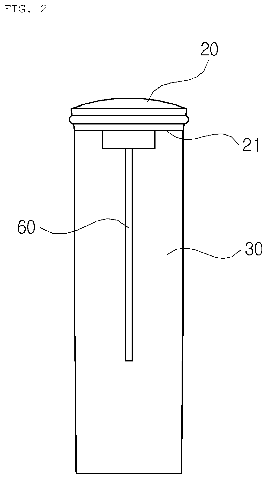
[0010] FIG. 2 is a front view according to a preferred embodiment of the present invention.
[0011] FIG. 3 is a side view according to a preferred embodiment of the preset invention.
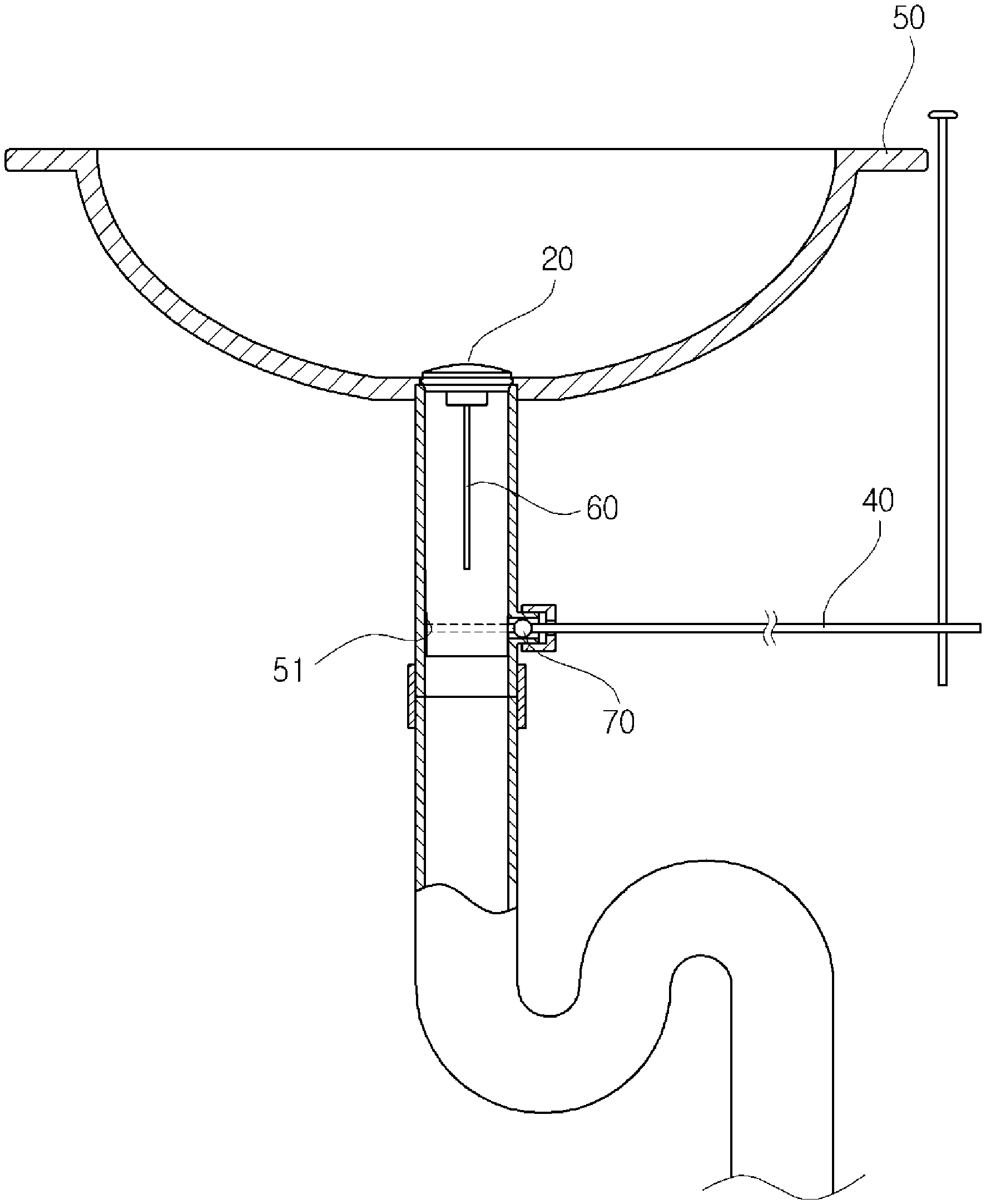
[0012] FIG. 4 is a view illustrating installation of a washbasin at a drain hole according to a preferred embodiment of the present invention.
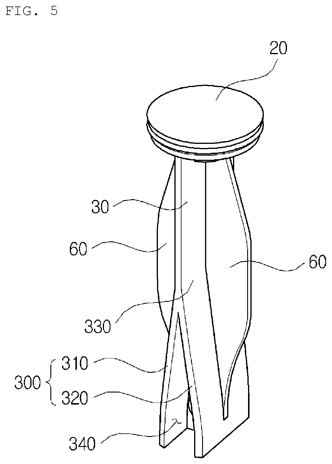
[0013] FIG. 5 is a view illustrating blades according to another embodiment of the present invention.
DESCRIPTION OF REFERENCE NUMERALS
[0014] 20: Head part [0015] 21: Bottom [0016] 30: Debris clogging prevention cover [0017] 40: Operating lever [0018] 50: Washbasin [0019] 51: Drain hole [0020] 60: Blade [0021] 70: Hinge axis [0022] 300: Cover member [0023] 310: First cover [0024] 311: First support [0025] 312: First hole [0026] 320: Second cover [0027] 321: Second support [0028] 322: Second hole [0029] 330: Curved face [0030] 340: Space
BEST MODE
[0031] Hereinafter, preferred embodiments of the present invention will be described in detail with reference to the accompanying drawings. First of all, with regard to reference numerals given to components shown in each drawing, it should be noted that even though the same components are shown in different drawings, these components have the same reference numerals as frequently as possible. In addition, the following description will be provided to explain the preferred embodiments of the present invention, however, the technical concepts of the present invention are not particularly restricted or limited thereto and, instead, can be modified and variously practiced by those skilled in the art.
[0032] First, a configuration of the washbasin pop-up valve according to an embodiment of the present invention will be described.
[0033] As shown in FIGS. 1 to 3, the washbasin pop-up valve according to the embodiment of the present invention may include a head part 20, a debris clogging prevention cover 30 disposed on the bottom of the head part 20, blades 30 to form a `+` shape together with the debris clogging prevention cover 30.
[0034] More particularly, the head part 20 may serve to open and close a drain hole 51 of the washbasin. The head part 20 may have a circular form corresponding to the drain hole 51 in order to plug up the drain hole 51. A typical elastic packing for closing the drain hole 51 may be coupled to a lateral face of the head part 20.
[0035] The debris clogging prevention cover 30 may be formed with a width corresponding to the drain hole. The debris clogging prevention cover 30 may extend downward from the bottom 21 of the head part 20. The debris clogging prevention cover 30 may act to prevent debris from sticking to the operating lever 40. The debris clogging prevention cover 30 may be connected to an operating lever 40.
[0036] The debris clogging prevention cover 30 may include a cover member 300 provided on a lower portion thereof to enclose the operating lever 40. The cover member 300 may be divided into two branches above the operating lever 40 while enclosing a lever portion of the operating lever 40 exposed within the drain hole 51 of the washbasin 50.
[0037] The cover member 300 may include a first cover 310 and a second cover 320 facing the first cover 310. There is a space 340 between the first cover 310 and the second cover 320, which is required to operate the operating lever 40. The first cover 310 and the second cover 320 may enclose the operating lever 40 in order to prevent debris such as hair from sticking to the operating lever 40.
[0038] A first support 311 may be provided inside the first cover 310. Further, a second support 321 facing the first support 311 may be provided inside the second cover 320. The first support 311 may have a first hole 312 surrounding half of the operating lever 40. The first hole 312 may have a semicircular shape. Further, the second support 321 may have a second hole 322 surrounding the other half of the operating lever 40, which is opposed to the first hole 312. The second hole 322 may also have a semicircular shape. The first hole 312 and the second hole 322 meet to form a single circle.
[0039] A connection face between an upper portion of the debris clogging prevention cover 30 and a lower portion of the same, that is, the cover member 300, is designed as a curved face 330 along which water or debris smoothly flows down. Blades 60 may be provided at front and rear sides of the debris clogging prevention cover 30. The debris clogging prevention cover 30 may be welded to the head part 20 or integrally coupled to the head part 20.
[0040] The blades 60 may be provided at both of the front side and the rear side of the debris clogging prevention cover 30. The blades 60 may form a `+` shape together with the debris clogging prevention cover 30. The blades 60 should be designed to be close to an inner wall surface of the drain hole 51 of the washbasin 50. The blades 60 may serve as a guide to ensure smooth flow of the water through the drain hole 51 and, at the same time, as a rib to reinforce durability of the debris clogging prevention cover 30.
[0041] As shown in FIG. 5, a shape of the blade 60 may be altered. More particularly, a lower portion of the blade 60 may be located below the debris clogging prevention cover 30, so as to reinforce rigidity of the debris clogging prevention cover 30.
[0042] The following description will be provided to explain operation of the washbasin pop-up valve according to an embodiment of the present invention.
[0043] As shown in FIG. 4, when pressing a stem connected to the operating lever 40 while plugging up the drain hole 51 by the head part 20, the operating lever 40 rotates about a hinge axis 70 and pushes up the pop-up valve by operation of the stem. While the pop-up valve is lifted up, the head part 20 plugging up the drain hole 51 escapes from the drain hole 51, thereby opening the drain hole 51.
[0044] When the drain hole 51 is opened, water and debris such as hair may be discharged through the drain hole 51. In this case, the lever portion (of the operating lever 40) exposed within the drain hole 51 is substantially shielded by the first cover 311 and the second cover 312, therefore, the debris flowing through the drain hole 51 does not stick to the exposed portion of the operating lever 40 inside the drain hole 51 but can be directly drained through the drain hole 51. More particularly, the debris smoothly flows along the outer surfaces of the first cover 311 and the second cover 312 and is discharged through the drain hole 51.
[0045] When pressing the head part 20 toward the drain hole 51, the operating lever 315 may return to an original position thereof while the drain hole 51 is plugged up by the head part 20.
[0046] The following description will be provided to explain a process of coupling the operating lever to the debris clogging prevention cover.
[0047] The conventional operating lever 40 is coupled to the debris clogging prevention cover by correctly fitting the operating lever 40 into a hole, and this coupling process is not easily conducted. However, according to the embodiment of the present invention, the operating lever 40 can be easily and simply coupled to the debris clogging prevention cover by pushing the same between the first cover 310 and the second cover 320.
[0048] In particular, when pushing the operating lever 315 between the first cover 310 and the second cover 320, the first cover 310 and the second cover 320 are naturally widened. More specifically, when pushing the operating lever 315 between the first cover 310 and the second cover 320, a narrow spacing between the first support 311 and the second support 321 is widened so that the operating lever 315 can enter the same and be disposed in the first hole 312 and the second hole 322 via the widened spacing. As soon as the operating lever 315 is located in the first hole 312 and the second hole 322, the first support 311 and the second support 321 are narrowed again to complete coupling of the operating lever 315.
[0049] As reviewed above, the washbasin pop-up valve according to the embodiments of the present invention may enclose a lever portion of the operating lever exposed within a drain hole by a debris clogging prevention cover, so as to fundamentally prevent debris, which is discharged through the drain hole, from sticking to the operating lever. Further, unlike the conventional coupling mode of the operating lever by correctly fitting the operating lever into a hole, the operating lever according to the present invention can be easily and simply coupled by pushing the operating lever into a first hole and a second hole.
[0050] As such, the above description is provided only to illustrate the technical concept of the present invention, and those skilled in the art will appreciate that a variety of modifications, alternations and substitutions may be possible within the scope of the present invention without departing from essential characteristics of the present invention. Accordingly, the embodiments and accompanying drawings are intended to explain the technical features of the present invention without particular limitation thereof, and the technical scope of the present invention is duly not limited by such embodiments and accompanying drawings. The protected scope of the present invention is to be interpreted by the appended claims, and all technical ideas within the above protected scope and equivalents thereto should be construed as within the scope of the present invention.
* * * * *
D00000
D00001
D00002
D00003
D00004
D00005
XML
uspto.report is an independent third-party trademark research tool that is not affiliated, endorsed, or sponsored by the United States Patent and Trademark Office (USPTO) or any other governmental organization. The information provided by uspto.report is based on publicly available data at the time of writing and is intended for informational purposes only.
While we strive to provide accurate and up-to-date information, we do not guarantee the accuracy, completeness, reliability, or suitability of the information displayed on this site. The use of this site is at your own risk. Any reliance you place on such information is therefore strictly at your own risk.
All official trademark data, including owner information, should be verified by visiting the official USPTO website at www.uspto.gov. This site is not intended to replace professional legal advice and should not be used as a substitute for consulting with a legal professional who is knowledgeable about trademark law.