Multipurpose Valve Cap
Howell; Bret
U.S. patent application number 16/216828 was filed with the patent office on 2020-06-11 for multipurpose valve cap. This patent application is currently assigned to Bret Howell. The applicant listed for this patent is Bret Howell. Invention is credited to Bret Howell.
| Application Number | 20200180829 16/216828 |
| Document ID | / |
| Family ID | 69143677 |
| Filed Date | 2020-06-11 |


View All Diagrams
| United States Patent Application | 20200180829 |
| Kind Code | A1 |
| Howell; Bret | June 11, 2020 |
MULTIPURPOSE VALVE CAP
Abstract
Devices and methods for a gas tank valve cap with integrated washer storage are disclosed. In examples, a valve cap may comprise a first cavity for covering a portion of a gas tank valve, and a second cavity for housing a washer/gasket. In examples, the washer/gasket may be removed from the valve cap and used to secure a connection between the gas tank valve and a connecting hose line. In further examples, the washer may be re-inserted into the valve cap, and the valve cap may be placed on the gas tank valve for protecting the valve from abrasion and the like.
| Inventors: | Howell; Bret; (Spokane, WA) | ||||||||||
| Applicant: |
|
||||||||||
|---|---|---|---|---|---|---|---|---|---|---|---|
| Assignee: | Howell; Bret Spokane WA |
||||||||||
| Family ID: | 69143677 | ||||||||||
| Appl. No.: | 16/216828 | ||||||||||
| Filed: | December 11, 2018 |
| Current U.S. Class: | 1/1 |
| Current CPC Class: | F17C 2221/013 20130101; F17C 2201/056 20130101; F17C 2201/0109 20130101; F17C 2205/0308 20130101; F17C 13/04 20130101; F17C 2201/058 20130101; B65D 51/1644 20130101; F17C 2205/0323 20130101 |
| International Class: | B65D 51/16 20060101 B65D051/16 |
Claims
1. A cap for covering at least a portion of a gas tank valve, comprising: a first cylindrical cavity having a first inside diameter and a first depth; a second cylindrical cavity having a second inside diameter and a second depth, the second inside diameter being smaller than the first inside diameter and the second depth being smaller than the first depth, wherein the first cavity and the second cavity have a common backplane; and a washer housed within the second cylindrical cavity, wherein at least one of the first cylindrical cavity or the second cylindrical cavity is composed of a pliable material such that, when squeezed with a threshold amount of force, the second cylindrical cavity releases at least a portion of the washer.
2. A cap as recited in claim 1, further comprising an inner rim disposed on at least a portion of the second cylindrical cavity and located at a distal end of the second cylindrical cavity with respect to the common backplane, the inner rim having an inside diameter smaller than an outside diameter of the washer.
3. A cap as recited in claim 1, further comprising a relief cut disposed in at least a portion of the second cylindrical cavity, the relief cut located at a distal end of the second cylindrical cavity with respect to the common backplane.
4. A cap as recited in claim 1, further comprising a removable tab coupled to at least a portion of the first cavity, the removeable tab configured to separate from the cap and release the portion of the gas tank valve when pulled.
5. A cap as recited in claim 1, further comprising a pull tab removeably coupled to a portion of the second cavity such that the pull tab covers the second cavity, the pull tag configured to separate from the second cavity and provide access to the washer situated within the second cavity.
6. A cap as recited in claim 5, wherein the protrusion includes a connection arm, the connection arm comprising a retainer ring located at a distal end of the connection arm with respect to the first cylindrical cavity, the retainer ring sized to fit over at least a portion of the gas tank valve.
7. A cap as recited in claim 1, further comprising a cover attached to at least a portion of an outside surface of the second cylindrical cavity, the cover sized to removably couple to at least a distal end of the second cylindrical cavity with respect to the common backplane and enclose the washer inside the second cylindrical cavity.
8. A cap comprising: a first cylindrical cavity having a first depth and being oriented in a first direction; a second cylindrical cavity having a second depth smaller than the first depth and oriented in a second direction opposite of the first direction, the second cylindrical cavity sized to house a washer therein; and wherein the first cylindrical cavity and the second cylindrical cavity share a common backplane.
9. A cap as recited in claim 8, wherein at least one of the first cylindrical cavity or the second cylindrical cavity is composed of a pliable material such that, when squeezed with a threshold amount of force, the second cylindrical cavity releases at least a portion of the washer.
10. A cap as recited in claim 8, further comprising an inner rim disposed on at least a portion of the second cylindrical cavity and being located at a distal end of the second cylindrical cavity with respect to the common backplane, the inner rim having an inside diameter smaller than an outside diameter of the washer.
11. A cap as recited in claim 8, further comprising a relief cut in at least a portion of the second cylindrical cavity, the relief cut being located at a distal end of the second cylindrical cavity with respect to the common backplane.
12. A cap as recited in claim 8, further comprising a protrusion disposed on at least a portion of an outside surface of the first cylindrical cavity and extending in a direction parallel to the common backplane.
13. A cap as recited in claim 12, wherein the protrusion includes a connection arm, the connection arm comprising a ring at a distal end of the connection arm with respect to the first cylindrical cavity, the ring being sized to fit over at least a portion of a gas tank valve.
14. A cap as recited in claim 8, further comprising a first thread disposed on at least a portion of an inner surface of the first cylindrical cavity, the first thread sized to mate with at least a portion of a gas tank valve.
15. A device comprising: a first cavity oriented in a first direction and sized to cover at least a portion of a gas tank valve; a second cavity oriented in a second direction opposite of the first direction and sharing a common backplane with the first cavity; and wherein second cavity is sized to house a washer therein.
16. A device as recited in claim 15, wherein at least one of the first cavity or the second cavity is composed of a pliable material such that, when squeezed with a threshold amount of force, the second cavity releases at least a portion of the washer.
17. A device as recited in claim 15, further comprising an inner rim disposed on at least a portion of the second cavity and located at a distal end of the second cavity with respect to the common backplane.
18. A device as recited in claim 15, further comprising a relief cut in at least a portion of the second cavity, the relief cut located at a distal end of the second cavity with respect to the common backplane.
19. A device as recited in claim 15, further comprising a first thread disposed on at least a portion of an inner surface of the first cavity, the first thread sized to mate with at least a portion of a gas tank valve.
20. A device as recited in claim 15, further comprising a connection arm disposed on at least a portion of an outside surface of at least one of the first cavity or the second cavity.
Description
BACKGROUND
[0001] When a compressed gas tank is shipped to a consumer, there may be a need to protect a valve of the gas tank and provide the consumer with a washer/gasket for connection of a hose to the valve of the tank. Typically, the valve may comprise a fluid/gas port that should be covered for protection against abrasion and/or contamination. Further, there may be a need to secure the washer/gasket to the tank valve for removal by the consumer upon connecting a hose to the valve of the tank. Therefore, a means to adequately protect the valve of a compressed gas tank, and/or another valve in general, and secure the washer/gasket to the valve for a future connection is desirable.
BRIEF DESCRIPTION OF THE DRAWINGS
[0002] The detailed description is set forth below with reference to the accompanying figures. In the figures, the left-most digit(s) of a reference number identifies the figure in which the reference number first appears. The use of the same reference numbers in different figures indicates similar or identical items. The systems depicted in the accompanying figures are not to scale and components within the figures may be depicted not to scale with each other.
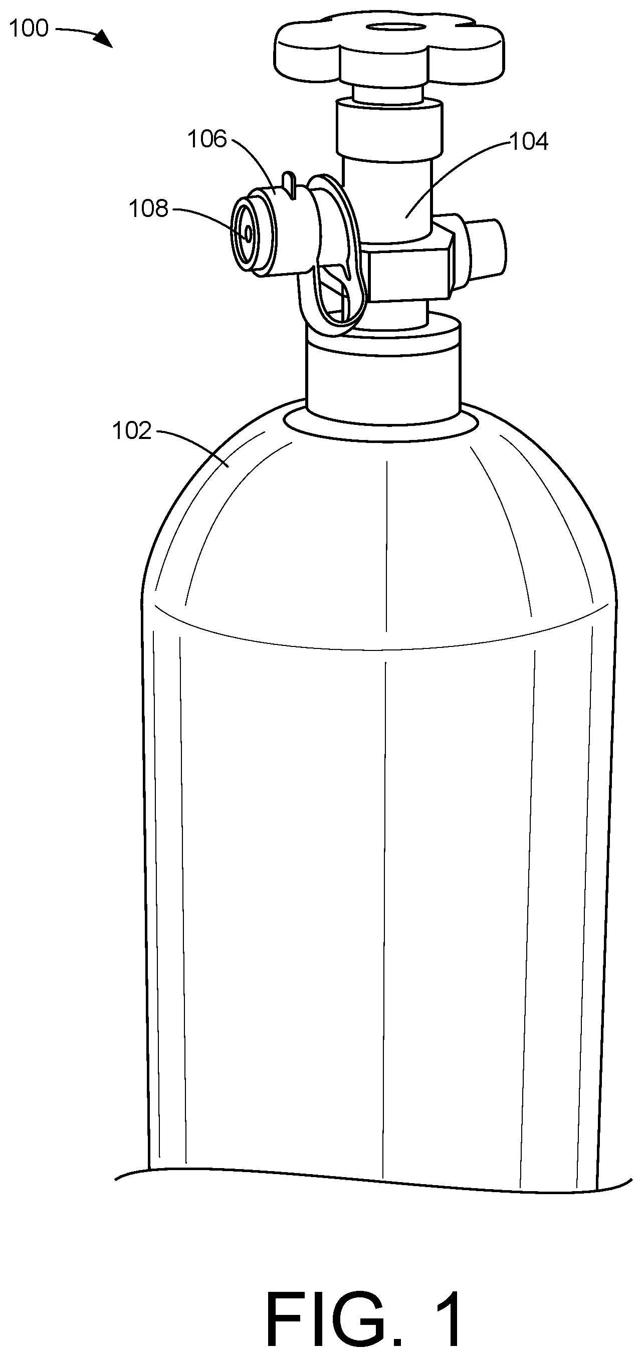
[0003] FIG. 1 illustrates an example multipurpose valve cap while in use on a gas tank valve.
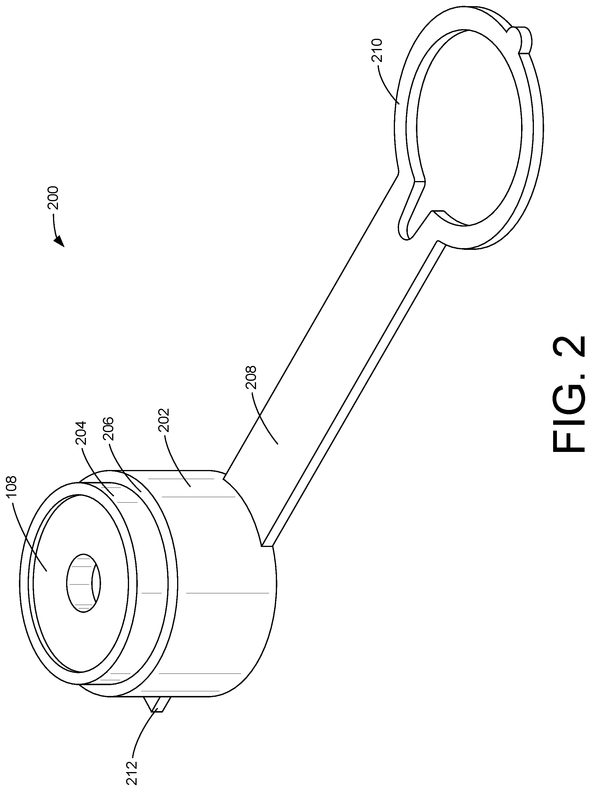
[0004] FIG. 2 illustrates a perspective view of an example multipurpose valve cap.
[0005] FIG. 3A illustrates an example multipurpose valve cap with force applied to displace a washer associated with the cap.
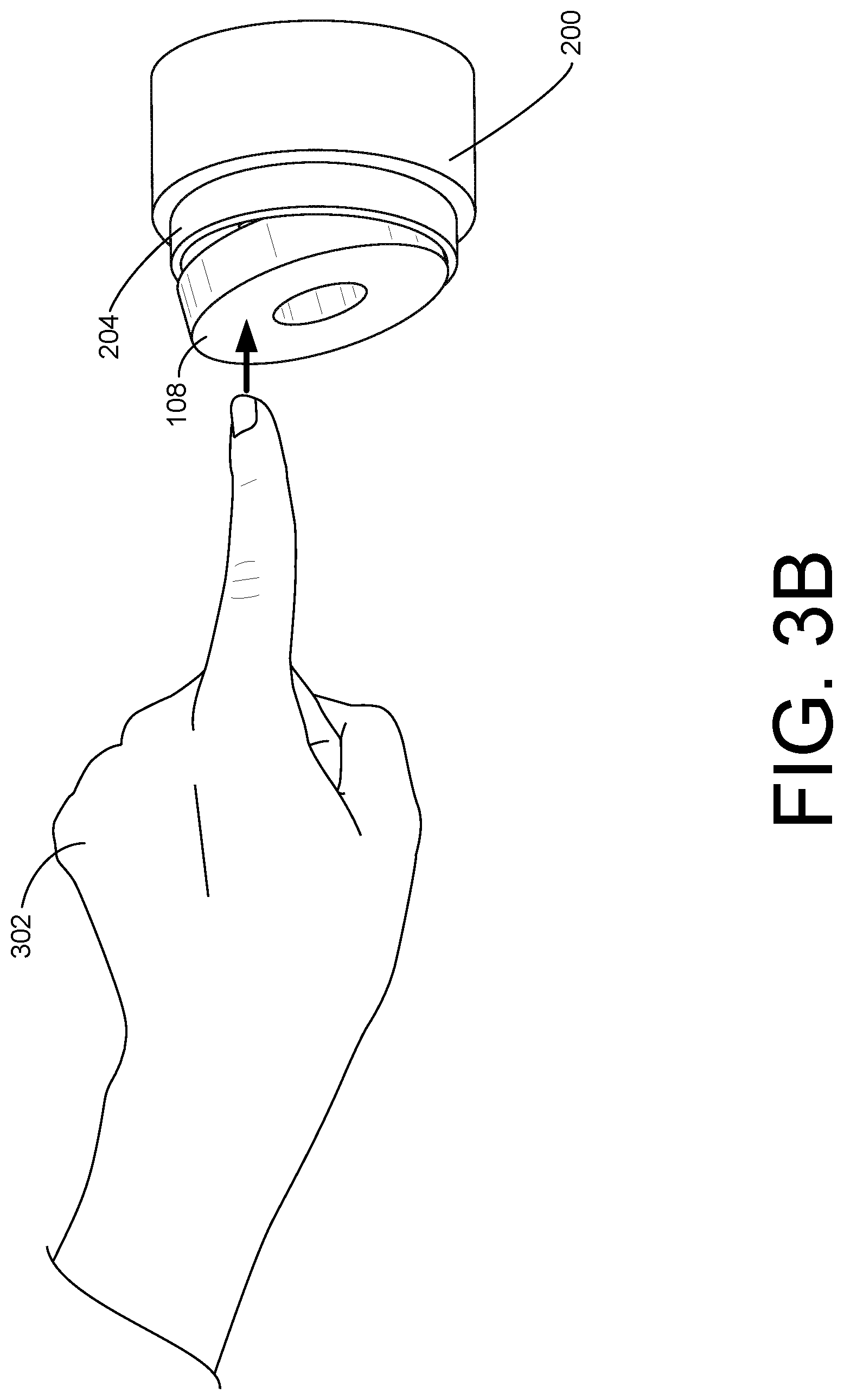
[0006] FIG. 3B illustrates an example multipurpose valve cap utilized to press a washer into the cap for storage.
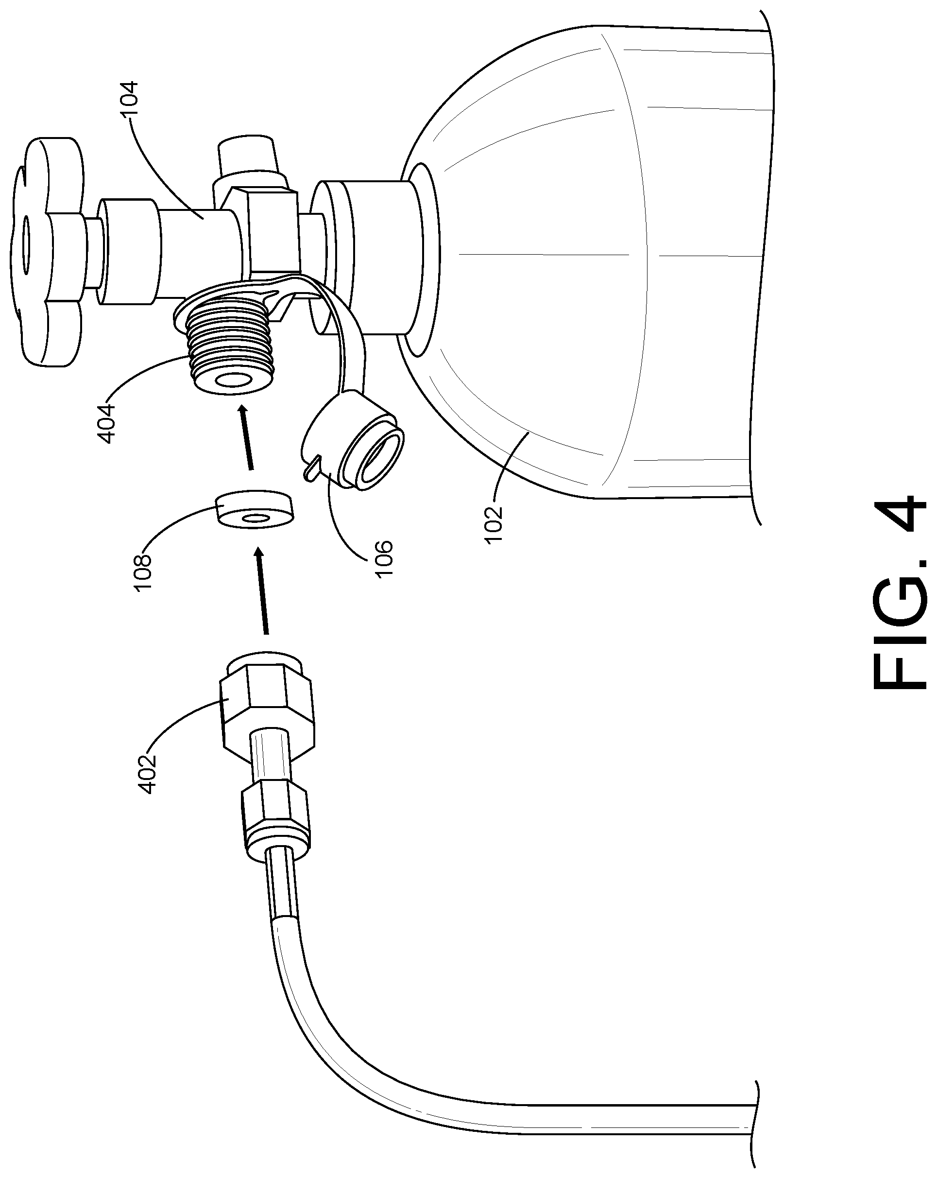
[0007] FIG. 4 illustrates an example multipurpose valve cap being connected to a compressed gas tank valve while the valve is connected to a hose.
[0008] FIG. 5 illustrates a cross-sectional view of an example multipurpose valve cap.
[0009] FIG. 6 illustrates a cross-sectional view of an example multipurpose valve cap with an example relief cut.
[0010] FIG. 7A illustrates a cross-sectional view of an example multipurpose valve cap comprising an inner rim for holding a washer in place.
[0011] FIG. 7B illustrates a cross-sectional view of an example multipurpose valve cap comprising grip tabs.
[0012] FIG. 7C illustrates a cross-sectional view an example multipurpose valve cap comprising internal threads.
[0013] FIG. 7D illustrates a cross-sectional view of an example multipurpose valve cap comprising a cover for holding the washer in place.
[0014] FIG. 8 is a flow diagram illustrating an example process for use of a multipurpose valve cap.
[0015] FIG. 9 illustrates a perspective view of an example multipurpose valve cap.
[0016] FIG. 10 illustrates a perspective view of another example multipurpose valve cap.
[0017] FIG. 11 illustrates a cross-sectional view of an example multipurpose valve cap.
DETAILED DESCRIPTION
[0018] Devices and related methods for multipurpose valve caps are disclosed herein. As discussed above, when a compressed gas tank is shipped to a consumer, there may be a need to protect a valve of the gas tank and provide the consumer with a washer/gasket to be used in connecting a hose and/or supply line to the valve of the tank. In examples, the connection point of the valve may be covered with a plastic cap for protecting the threads and/or the fluid/gas port. Further, the washer/gasket may be secured to the valve of the gas tank by a rubber band, zip tie, wire, or the like.
[0019] The present disclosure describes devices that may be used to cover a connection point of a valve and store a washer/gasket. The embodiments are described with specificity in order to meet statutory requirements. However, the description itself is not intended to limit the scope of this application and/or patent. Rather, the inventor has contemplated that the claimed invention might also be embodied in other ways, to include different elements or combinations of elements similar to the ones described in this document, in conjunction with other present and/or future technologies.
[0020] In examples, the devices described herein may be structured to have a first cavity sized to fit over a portion of a compressed gas tank valve and a second cavity sized to house a washer therein. Accordingly, the first cavity and the second cavity may share a common backplane and may be positioned such that an opening of the first cavity and an opening of the second cavity are oriented in opposite directions. Additionally, or alternatively, the first cavity and the second cavity may be different sizes, such as a different depth and/or diameter. For example, the first cavity may have a first depth and diameter and the second cavity may have a second depth and diameter. In further examples, the first cavity and the second cavity may be the same size.
[0021] Additionally, or alternatively, the devices may be injection molded and composed of various materials. For instance, the device may be completely composed of polypropylene, polyethylene, silicon, and/or another pliable material. Additionally, or alternatively, the device may be composed of a combined mixture of the materials listed above. In even further examples, components of the device may be composed of different materials. For instance, the first cavity may be composed of a solid metal alloy while the second cavity may be composed of a pliable material such as polypropylene.
[0022] In examples, an inside surface of the first cavity may have different compositions. For example, the inside surface of the first cavity may be smooth. In other examples, the inside surface of the first cavity may comprise female threading sized to mate with male threading disposed on the valve of the gas tank. Additionally, or alternatively, the inside surface of the first cavity may comprise an inner rim. In even further examples, the inside surface of the first cavity may comprise one or more grooves to produce added friction between the inside surface of the first cavity and the gas tank valve.
[0023] The second cavity of the devices described herein may take many different physical forms and sizes, and should not be limited in scope by the examples provided herein. For instance, the second cavity may comprise an inner rim at the distal end of the second cavity with respect to the common backplane. In examples, the inside diameter of the inner rim may be smaller than an outside diameter of the washer. Accordingly, the inner rim may protrude from the inner surface of the second cavity anywhere from about 2-10 thousandths of an inch (0.002''-0.01''). Additionally, or alternatively, the second cavity may further comprise one or more relief cuts in the distal end of the second cavity extending through the inner rim. The one or more relief cuts may allow for easier removal of a washer housed within the second cavity. In even further examples, the second cavity may further comprise a cover attached to at least a portion of the outside surface of the second cavity for securing the washer in place. The cover may further be used in conjunction with the inner rim and/or the one or more relief cuts described above.
[0024] In examples, the washer may be any device used for enabling a proper connection between a gas tank valve and another device, such as a hose, a gauge, and/or a meter. The technical term washer should not be read as far as to limit the scope of the described devices. For instance, the technical term washer may encompass similar terms such as gasket, seal, ring, spacer, and other terms that would be readily known to those with skill in the art. In examples the washer may be composed of different materials, such as nylon, rubber, polypropylene, metal, silicon, and other materials known in the art. The washer may also have varying dimensions in thickness and width, and may not be universally sized in an industry standard.
[0025] The first cavity and/or the second cavity may further comprise one or more protrusions. For instance, the one or more protrusions may consist of a connection arm. The connection arm may further comprise a retainer ring located at the distal end of the connection arm with respect to the first cavity and the second cavity. In examples, the retainer ring may be sized such that the valve of the gas tank may be inserted through the retainer ring. In this way, the device may be secured to the valve of the gas tank via the connection arm when the valve is not inserted into the first cavity.
[0026] The one or more protrusions may also include a tab to assist in removing the first cavity from a gas tank valve. In examples, the tab may be disposed at any point along the circumference of the first cavity. The location of the tab may not be limited however to the first cavity, and could be, for example, attached to the second cavity. In further examples, the one or more protrusions may also include one or more grip tabs to assist a user while squeezing the device to release a washer housed within the second cavity.
[0027] The present disclosure provides an overall understanding of the principles of the structure, function, manufacture, and use of the devices and methods disclosed herein. One or more examples of the present disclosure are illustrated in the accompanying drawings. Those of ordinary skill in the art will understand that the devices and methods specifically described herein and illustrated in the accompanying drawings are non-limiting embodiments. The features illustrated or described in connection with one embodiment may be combined with the features of other embodiments, including as between devices and methods. Such modifications and variations are intended to be included within the scope of the appended claims.
[0028] Additional details are described below with reference to several example embodiments.
[0029] FIG. 1 is an example system 100 illustrating how a multipurpose valve cap may be used. As shown in FIG. 1, the system 100 may comprise a compressed gas tank 102, a valve 104, and the valve cap 106.
[0030] In examples, the compressed gas tank 102 may be a CO.sub.2 cylinder, such as a CO.sub.2 cylinder used in a soda fountain. In other instances, the compressed gas tank 102 may be an oxygen tank, nitrogen tank, helium tank, and/or the like. The compressed gas tank 102 may further exist in many different sizes, and may not be limited to a single industry. For example, the compressed gas tank 102 may be an oxygen tank for use in welding.
[0031] As shown by FIG. 1, the valve 104 may be attached to the compressed gas tank 102. In examples, the valve 104 may be composed of different materials. For example, the valve may be composed of brass, aluminum, copper, iron, and/or some other material known in the art. The valve 104 may comprise one or more connection points for attaching a hose and/or supply line.
[0032] The valve cap 106 may be sized to cover a portion of the valve 104. In examples, the valve cap 106 may cover a threaded portion of the valve 104. In other examples, the valve cap 106 may cover the entire valve 104.
[0033] The valve cap 106 may comprise a retainer ring and a connection arm that further secure the valve cap 106 to the gas tank valve 104. For example, the retainer ring and connection arm may keep the valve cap attached to the gas tank valve 104 when a hose is connected to the connection point of the valve 104 and the fluid/gas port does not need to be protected by the valve cap 106. In this way, when the hose is later disconnected, the connection point of the gas tank valve 104 may be re-inserted into the valve cap 106 for protection.
[0034] The valve cap 106 may further house a washer 108. The washer 108 may be removed from the housing of the valve cap 106 and may be used in establishing a proper connection between a connection point of the gas tank valve 104 and an attaching hose line. In examples, the washer 108 may be re-inserted into the valve cap 106 after disconnecting the attaching hose line. Accordingly, the washer 108 may be stored for later use. In examples, the washer 108 may include one or more protrusions and/or bulges configured to mate with and/or sink into grooves in a hose fitting and/or tank valve and/or grooves within the second cavity.
[0035] As noted above, the valve cap 106 may be advantageous in comparison to traditional valve caps. For example, because the valve cap 106 may house a washer 108, other means for securing the washer 108 to the gas tank valve 104 for shipping to a consumer may not be necessary. Additionally, or alternatively, the valve cap 106 may secure the washer 108 to the gas tank valve 104 more safely and/or effectively, therefore preventing the washer 108 from being disconnected from the gas tank valve 104 during shipping.
[0036] FIG. 2 illustrates a perspective view of an example multipurpose valve cap. As shown, the exemplary device 200 may have several different components.
[0037] The exemplary device 200 may comprise a first cavity 202 sized to cover at least a portion of a gas tank valve. In examples, the first cavity 202 may have a first diameter and a first cavity depth. The first cavity 202 may further comprise threading on the inside surface of the cavity sized to mate with threading on the gas tank valve 106. In other examples, the inside surface of the first cavity 202 may be smooth, such that the first cavity may slide over threading disposed on the gas tank valve 106.
[0038] The exemplary device 200 may also comprise a second cavity 204. The second cavity 204 may be sized to house a washer 108 therein, and may share a common backplane 206 with the first cavity. As shown, the orientation of the second cavity 204 may be in a direction opposite that of the first cavity 202. In examples, the second cavity 204 may have a second diameter and a second cavity depth. For example, the second diameter and second cavity depth may each be different than the first diameter and first cavity depth of the first cavity 202. In other examples, the first cavity depth and the second cavity depth may be the same. Additionally, or alternatively, the first cavity diameter and the second cavity diameter may be the same.
[0039] The second cavity 204 may further comprise an inner rim disposed at the distal end of the second cavity with respect to the common backplane 206. In examples, the inner rim may have an inside diameter that is smaller than an outside diameter of the washer 108, thereby enabling the second cavity 204 to retain the washer 108. In other examples, the second cavity 204 may comprise a cover that is attached to at least a portion of the exemplary device 200. For example, the cover may be sized to fit over the second cavity to secure the washer 108 within the second cavity.
[0040] In examples, the second cavity 204 may further comprise a relief cut. For instance, the second cavity 204 may comprise a relief cut extending from the common backplane 206 to the distal end of the second cavity with respect to the common backplane 206. The relief cut may assist in removing the washer 108 that may be housed in the second cavity 204.
[0041] As noted above, the exemplary device 200 may comprise a washer 108. The washer 108 may be used for connecting a hose and/or other device to the gas tank valve 104. In examples, the washer 108 may be composed of various materials. For instance, the washer 108 may be composed of nylon, rubber, silicon, polypropylene, metal, and/or another substance.
[0042] As mentioned above, the exemplary device 200 may comprise a common backplane 206 joining the first cavity 202 with the second cavity 204. In examples, the common backplane 206 may vary in thickness depending on the size of the first cavity 202 and the second cavity 204. For example, the common backplane 206 may be thin, thereby creating a more pliable device that may be easier to remove a washer from. Alternatively, the common backplane 206 may be thicker to produce a more rigid device that is not easily manipulated.
[0043] In examples, the first cavity 202 and the second cavity 204 of the exemplary device 200 may be two separate components that are coupled together with the common backplane 206 separating the two components. In other examples, the first cavity 202 and the second cavity 204 may be a single component such that the common backplane 206 comprises at least a portion of the first cavity 202 and at least a portion of the second cavity 204.
[0044] Additionally, or alternatively, the exemplary device 200 may comprise one or more protrusions. The one or more protrusions may include a connection arm 208. In examples, the connection arm 208 may comprise a retainer ring 210 sized to fit over a valve connection point of the gas tank valve 104. In this way, the valve connection point may be inserted through the retainer ring 210 before inserting the valve connection point into the first cavity 202. Accordingly, when the first cavity is removed from the valve connection point, the retainer ring 210 may keep the exemplary device 200 connected to the gas tank valve 104.
[0045] In examples, the one or more protrusions may also include a tab 212 for assisting a user of the exemplary device 200 in removing the first cavity 202 from the valve connection point of the gas tank valve 104. In this way, the tab 212 may assist the user by providing leverage and/or additional grip to pry the first cavity 202 away from the connection point of the gas tank valve 104.
[0046] FIG. 3A illustrates an example multipurpose valve cap with force applied to displace a washer associated with the cap. When the exemplary device 200 is squeezed by a user 302, the device may release the washer 108 from the second cavity 204.
[0047] In examples, the user 302 may apply a threshold amount of force to the exemplary device 200 to release the washer 108 housed within the second cavity 204. For example, the user 302 may squeeze the device in a direction about parallel to the common backplane of the exemplary device 200 to release the washer 108. In other examples, the user 302 may pry the washer 108 out of the second cavity 204.
[0048] FIG. 3B illustrates an example multipurpose valve cap utilized to press a washer into the cap for storage. When the washer 108 is pressed into the second cavity 204 of the exemplary device 200 with a threshold amount of force, the second cavity 204 may retain the washer 108 therein.
[0049] In examples, a user 302 may snap the washer 108 into the second cavity 204 if the second cavity comprises an inner rim for retaining the washer 108. Accordingly, depending on the inside diameter of the inner rim, the threshold amount of force applied by the user 302 may vary.
[0050] FIG. 4 illustrates an example multipurpose valve cap being connected to a compressed gas tank valve while the valve is connected to a hose. As shown in FIG. 4, the washer 108 may be removed from the valve cap 106 and thereby used for connecting a hose 402 to a connection point 404 of a gas tank valve 104.
[0051] In examples, when the gas tank 102 is in use and a hose 402 is attached to the connection point 404 of the gas tank valve 104, the connection arm and retainer ring keep the device 106 connected to the gas tank valve 104. In this way, if the hose 402 is later disconnected, the connection point 404 may be re-inserted into the device 106 to protect against abrasion, contamination, and/or the like. Additionally, the washer 108 may be re-inserted into the second cavity of the device 106 if desired for storage until a new connection may be desired.
[0052] FIG. 5 illustrates a cross-sectional view of an example multipurpose valve cap. As shown in more detail in FIG. 5, the exemplary device 200 may comprise a common backplane 206 where the distal ends of the first cavity and the second cavity may be disposed. Additionally, as noted above and shown in more detail in FIG. 5, the first cavity and the second cavity may be a single component such that the common backplane 206 comprises at least a portion of the first cavity and at least a portion of the second cavity.
[0053] Additionally, or alternatively, the thickness of the common backplane 206 may vary depending on the desired pliability of the exemplary device 200. For instance, the common backplane 206 may be sized thicker to create a more rigid exemplary device 200. Alternatively, the common backplane 206 may be sized thinner to create a less rigid exemplary device 200.
[0054] FIG. 6 illustrates a cross-sectional view of an example multipurpose valve cap with an example relief cut. In examples, the second cavity may have one or more relief cuts 602 extending from the common backplane through the distal end of the second cavity. The one or more relief cuts 602 may assist the user in releasing the washer from the second cavity. For example, the one or more relief cuts 602 may cause the second cavity to be more pliable and more easily manipulated for a user to release the washer.
[0055] In examples, the one or more relief cuts 602 may be spaced at even intervals around the circumference of the second cavity if the total number of relief cuts 602 is greater than one. Additionally, or alternatively, the one or more relief cuts 602 may vary in thickness. For example, if a more pliable second cavity is desired, more material from the second cavity may be removed when the one or more relief cuts 602 are inserted. Alternatively, if a less pliable second cavity is desired, less material from the second cavity may be removed when the one or more relief cuts 602 are inserted.
[0056] FIG. 7A illustrates a cross-sectional view of an example multipurpose valve cap comprising an inner rim for holding a washer in place. As shown in FIG. 7A, the inner rim 702 may be disposed on the second cavity at the distal end of the cavity with respect to the common backplane. In examples, the inside diameter of the inner rim 702 may be smaller than an outside diameter of the washer. Accordingly, the inner rim 702 may protrude from the inner surface of the second cavity anywhere from about 2-10 thousandths of an inch (0.002''-0.01'').
[0057] In examples, the inner rim 702 may be a single, solid rim disposed on the entire inside circumference of the second cavity of the exemplary device 200. In other examples, the inner rim 702 may be a series of one or more intermittent "bumps" evenly spaced along the inside circumference of the second cavity.
[0058] FIG. 7B illustrates a cross-sectional view of an example multipurpose valve cap comprising grip tabs. In examples, the exemplary device 200 may have one or more grip tabs 704. The one or more grip tabs 704 may assist a user in squeezing the exemplary device 200 to release the washer from the second cavity.
[0059] As noted earlier, the exemplary device 200 may be composed of a pliable material. Such pliable material may be tough for a user to grip for squeezing the exemplary device 200 in order to release the washer from the second cavity. In examples, the one or more grip tabs 704 may make the exemplary device 200 easier to hold when squeezing the exemplary device 200. Additionally, or alternatively, the one or more grip tabs 704 may assist in inserting the connection point of the gas tank valve into the first cavity of the exemplary device 200 for protection.
[0060] FIG. 7C illustrates a cross-sectional view of an example multipurpose valve cap comprising internal threads. In examples, the inside surface of the first cavity of the exemplary device 200 may comprise female threading 706 sized to mate with male threading disposed on the connection point of the gas tank valve. In this way, the first cavity of the exemplary device 200 may be threaded onto the connection point of the gas tank valve rather than pressed on.
[0061] Additionally, or alternatively, the outside surface of the second cavity may comprise male threading sized to mate with female threading disposed on the connection point of the gas tank valve. In this way, the device 200 may be mated with both male and/or female gas tank valves.
[0062] FIG. 7D illustrates a cross-sectional view of an example multipurpose valve cap comprising a cover for holding the washer in place. In examples, the second cavity of the exemplary device 200 may further comprise a cover 708. The cover 708 may be attached to at least a portion of an outside surface of the first cavity and/or the second cavity. The cover 708 may be sized to enclose the second cavity and thereby secure the washer in place.
[0063] Additionally, or alternatively, the cover 708 may further be used in conjunction with the inner rim and/or the one or more relief cuts described above. In this way, the washer may be more securely housed within the second cavity.
[0064] FIG. 8 is a flow diagram illustrating an example process for use of a multipurpose valve cap. The process 800 may be performed by a user of the device, a machine, and/or another operator capable of performing the example process.
[0065] The process 800 (as well as each process described herein) is illustrated as a logical flow graph, each operation of which represents a sequence of operations that can be implemented by a user. The order in which the operations are described is not intended to be construed as a limitation, and any number of the described operations can be combined in any order and/or in parallel to implement the process. Further, any number of the described operations may be omitted.
[0066] At 802, the process 800 may begin by connecting the exemplary device to the gas tank valve with the retainer ring. In doing this, the connection point of the gas tank valve may be inserted through the retainer ring of the device.
[0067] At 804, the first cavity of the exemplary device may be mated with the connection point of the gas tank valve. As described above, in examples the first cavity of the exemplary device may be pressed onto the connection point, while in other examples the first cavity may be threaded onto the connection point via threading disposed on a surface of the first cavity.
[0068] At 806, the washer may be pressed into the second cavity for storage. In examples, the washer may snap into the second cavity if the second cavity comprises an inner rim. Additionally, or alternatively, the washer may be secured by a cover that encloses the washer within the second cavity.
[0069] At 808, the first cavity of the exemplary device may be removed from the connection point of the gas tank valve. In doing this, a tab of the exemplary device may be pulled on for removing the first cavity from the connection point. Alternatively, or additionally, the first cavity may be un-threaded from the connection point.
[0070] At 810, the exemplary device may be squeezed with a threshold amount of force in order to release the washer from the second cavity of the exemplary device. Grip tabs may be used to grip the exemplary device easier while squeezing. Alternatively, or additionally, the cover may be removed from the second cavity before removing the washer.
[0071] At 812, the second cavity of the exemplary device may release at least a portion of the washer. The washer may then be to connect a hose to the gas tank valve.
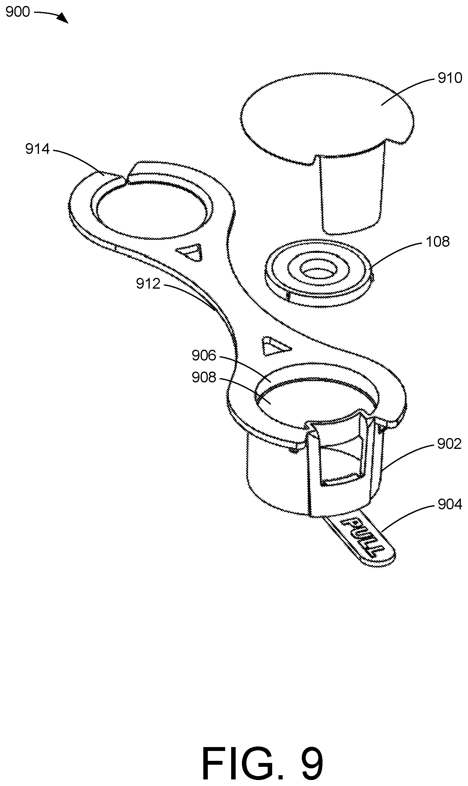
[0072] FIG. 9 illustrates a perspective view of an example multipurpose valve cap 900.
[0073] The exemplary device 900 may comprise a first cavity 902 sized to cover at least a portion of a gas tank valve. In examples, the first cavity 902 may have a first diameter and a first cavity depth. The first cavity 902 may be constructed of a pliable material such that the first cavity 902 may at least partially stretch to receive the portion of the gas tank valve. The first cavity 902 may also include a removable tab 904, which may, when pulled by a user, cause the removable tab 904 to at least partially break away and/or pull apart from the rest of the first cavity 902. By so doing, a user may gain access to the portion of the gas tank valve. The removable tab 904 may provide a visual indication that the gas tank valve has or has not been accessed.
[0074] The exemplary device 900 may also comprise a second cavity 906. The second cavity 906 may be sized to house a washer 108 therein, and may share a common backplane 908 with the first cavity 902. As shown, the orientation of the second cavity 906 may be in a direction opposite that of the first cavity 902. In examples, the second cavity 906 may have a second diameter and a second cavity depth. For example, the second diameter and second cavity depth may each be different than the first diameter and first cavity depth of the first cavity 902. In other examples, the first cavity depth and the second cavity depth may be the same. Additionally, or alternatively, the first cavity diameter and the second cavity diameter may be the same.
[0075] The second cavity 906 may further comprise an inner rim disposed at the distal end of the second cavity 906 with respect to the common backplane 908. In examples, the inner rim may have an inside diameter that is smaller than an outside diameter of the washer 108, thereby enabling the second cavity 906 to retain the washer 108. In other examples, the second cavity 906 may comprise a cover that is attached to at least a portion of the exemplary device 900. For example, the cover may be sized to fit over the second cavity to secure the washer 108 within the second cavity. In other examples, a pull tab 910 may be removably coupled to at least a portion of the second cavity 906 such that the washer 108 is secured in the second cavity 906 by the pull tab 910. In examples, the pull tab 910, when coupled to the second cavity 906, may provide a sanitary and/or clean environment for the washer 108 until the pull tab 910 is removed. The pull tab 910 may also provide a visual indication to a user of the device 900 that the washer 108 has not been utilized and/or the tank has not been used.
[0076] As noted above, the exemplary device 900 may comprise a washer 108. The washer 108 may be used for connecting a hose and/or other device to the gas tank valve. In examples, the washer 108 may be composed of various materials. For instance, the washer 108 may be composed of nylon, rubber, silicon, polypropylene, metal, and/or another substance.
[0077] As mentioned above, the exemplary device 900 may comprise a common backplane 908 joining the first cavity 902 with the second cavity 906. In examples, the common backplane 908 may vary in thickness depending on the size of the first cavity 902 and the second cavity 906. For example, the common backplane 908 may be thin, thereby creating a more pliable device that may be easier to remove a washer from. Alternatively, the common backplane 908 may be thicker to produce a more rigid device that is not easily manipulated.
[0078] Additionally, or alternatively, the exemplary device 900 may comprise one or more protrusions. The one or more protrusions may include a connection arm 912. In examples, the connection arm 912 may comprise a retainer ring 914 sized to fit over a valve connection point of the gas tank valve. In this way, the valve connection point may be inserted through the retainer ring 914 before inserting the valve connection point into the first cavity 902. Accordingly, when the first cavity 902 is removed from the valve connection point, the retainer ring 914 may keep the exemplary device 900 connected to the gas tank valve. In examples, a retention tooth on the interior wall of the device 900 may be replaced with an annular retention ring 914. The annular retention ring 914 may be manufactured and/or formed utilizing a floating core in the mold used to make the device 900. In other examples, the device 900 may include the annual retention ring 914 and a retention tooth.
[0079] FIG. 10 illustrates a perspective view of another example multipurpose valve cap 1000. The device 1000 may be the same or similar to the device 900 described with respect to FIG. 9. For example, the device 1000 may include a first cavity 902, a removable tab 904, a second cavity and a common backplane (not shown as covered by a pull tab 910), a connection arm 912, and/or a retainer ring 914. These components may function in the same or a similar manner to the components described with respect to FIG. 9.
[0080] As shown in FIG. 10, the pull tab 910 may be removably coupled to other portions of the device 1000. For example, the pull tab 910 may be coupled to at least a portion of the removeable tab 904, at least a portion of the first cavity 902, at least a portion of the second cavity, and/or at least a portion of the connection arm 912. When coupled, the pull tab 910 may provide a substantially air tight and/or water tight seal to the second cavity, which may hold the washer 108 therein. The pull tab 910, in examples, may include one or more writings, such as advertising and/or coloring for color codes, which may be used by one skill in the art to identify the washer and/or type of washer held within the second cavity. Once a user pulls the pull tab 910, it may be removed from the rest of the device 1000, revealing the washer 108. Additionally, or alternatively, pulling on the removable tab 904 may cause the pull tab 910 to break and/or separate from the second cavity.
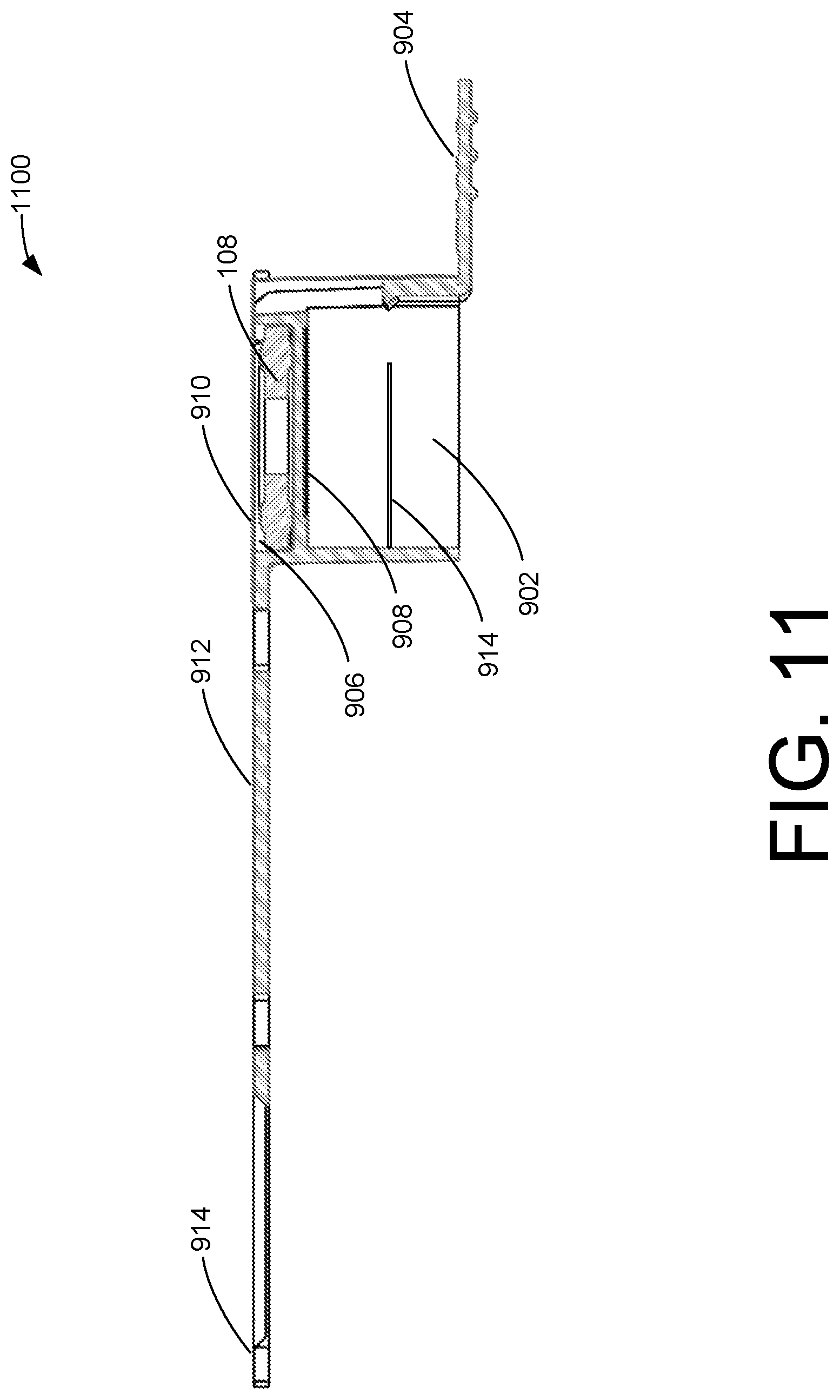
[0081] FIG. 11 illustrates a cross-sectional view of an example multipurpose valve cap 1100. The device 1100 may be the same or similar to the device 900 described with respect to FIG. 9. For example, the device 1100 may include a first cavity 902, a removable tab 904, a second cavity 906, a common backplane 908, a pull tag 910, a connection arm 912, and/or a retainer ring 914. These components may function in the same or a similar manner to the components described with respect to FIG. 9.
[0082] As shown in FIG. 11, the washer 108 may be housed within the second cavity 906, such as between the common backplane 908 and the pull tag 910. When coupled, the pull tab 910 may provide a substantially air tight and/or water tight seal to the second cavity, which may hold the washer 108 therein. The pull tab 910, in examples, may include one or more writings, such as advertising and/or coloring for color codes, which may be used by one skill in the art to identify the washer and/or type of washer held within the second cavity. Once a user pulls the pull tab 910, it may be removed from the rest of the device 1100, revealing the washer 108. Additionally, or alternatively, pulling on the removable tab 904 may cause the pull tab 910 to break and/or separate from the second cavity.
[0083] While the foregoing invention is described with respect to the specific examples, it is to be understood that the scope of the invention is not limited to these specific examples. Since other modifications and changes varied to fit particular operating requirements and environments will be apparent to those skilled in the art, the invention is not considered limited to the example chosen for purposes of disclosure, and covers all changes and modifications which do not constitute departures from the true spirit and scope of this invention.
[0084] Although the application describes embodiments having specific structural features and/or methodological acts, it is to be understood that the claims are not necessarily limited to the specific features or acts described. Rather, the specific features and acts are merely illustrative of embodiments that fall within the scope of the claims of the application.
* * * * *
D00000
D00001
D00002
D00003
D00004
D00005
D00006
D00007
D00008
D00009
D00010
D00011
XML
uspto.report is an independent third-party trademark research tool that is not affiliated, endorsed, or sponsored by the United States Patent and Trademark Office (USPTO) or any other governmental organization. The information provided by uspto.report is based on publicly available data at the time of writing and is intended for informational purposes only.
While we strive to provide accurate and up-to-date information, we do not guarantee the accuracy, completeness, reliability, or suitability of the information displayed on this site. The use of this site is at your own risk. Any reliance you place on such information is therefore strictly at your own risk.
All official trademark data, including owner information, should be verified by visiting the official USPTO website at www.uspto.gov. This site is not intended to replace professional legal advice and should not be used as a substitute for consulting with a legal professional who is knowledgeable about trademark law.