Epicardial Anchor Devices And Methods
Vidlund; Robert M. ; et al.
U.S. patent application number 16/790875 was filed with the patent office on 2020-06-11 for epicardial anchor devices and methods. This patent application is currently assigned to Tendyne Holdings, Inc.. The applicant listed for this patent is Tendyne Holdings, Inc.. Invention is credited to Mark Christianson, Craig Ekvall, Robert M. Vidlund.
| Application Number | 20200179112 16/790875 |
| Document ID | / |
| Family ID | 55262613 |
| Filed Date | 2020-06-11 |


View All Diagrams
| United States Patent Application | 20200179112 |
| Kind Code | A1 |
| Vidlund; Robert M. ; et al. | June 11, 2020 |
Epicardial Anchor Devices And Methods
Abstract
Apparatus and methods are described herein for anchoring a prosthetic heart valve. In some embodiments, an apparatus includes a tether attachment member that includes a base member that defines at least a portion of a tether passageway through which a portion of a tether extending from a prosthetic heart valve can be received therethrough. The base member defines a locking pin channel that intersects the tether passageway. A locking pin is disposable within the locking pin channel and movable between a first position in which the locking pin is at a spaced distance from the tether passageway, and a second position in which the locking pin intersects the tether passageway and can engage the portion of a tether disposed therein to secure the tether to the tether attachment member.
| Inventors: | Vidlund; Robert M.; (Forest Lake, MN) ; Christianson; Mark; (Plymouth, MN) ; Ekvall; Craig; (East Bethel, MN) | ||||||||||
| Applicant: |
|
||||||||||
|---|---|---|---|---|---|---|---|---|---|---|---|
| Assignee: | Tendyne Holdings, Inc. St. Paul MN |
||||||||||
| Family ID: | 55262613 | ||||||||||
| Appl. No.: | 16/790875 | ||||||||||
| Filed: | February 14, 2020 |
Related U.S. Patent Documents
| Application Number | Filing Date | Patent Number | ||
|---|---|---|---|---|
| 15001727 | Jan 20, 2016 | 10610354 | ||
| 16790875 | ||||
| PCT/US2014/049218 | Jul 31, 2014 | |||
| 15001727 | ||||
| 14224764 | Mar 25, 2014 | |||
| PCT/US2014/049218 | ||||
| 61861356 | Aug 1, 2013 | |||
| 14224764 | ||||
| 61861356 | Aug 1, 2013 | |||
| 61895975 | Oct 25, 2013 | |||
| Current U.S. Class: | 1/1 |
| Current CPC Class: | A61B 17/0057 20130101; A61F 2/2457 20130101; A61B 2017/00477 20130101; A61B 2017/0464 20130101; A61F 2220/0008 20130101; A61B 17/0401 20130101; A61B 2017/0453 20130101; A61B 2090/3966 20160201; A61B 2017/0414 20130101; A61B 2017/0404 20130101; A61B 2017/00243 20130101; A61F 2230/0069 20130101; A61B 2017/0409 20130101; A61B 2017/0061 20130101; A61B 2017/00575 20130101; A61B 2017/0448 20130101; A61B 2017/0417 20130101; A61B 17/0487 20130101; A61F 2/2418 20130101 |
| International Class: | A61F 2/24 20060101 A61F002/24; A61B 17/04 20060101 A61B017/04; A61B 17/00 20060101 A61B017/00 |
Claims
1. A method of securing a prosthetic heart valve to a heart, the method comprising: inserting a portion of a tether into a tether passageway defined by a tether attachment member, the tether extending from the prosthetic heart valve; disposing the tether attachment member adjacent an opening in a ventricular wall of the heart from which the tether extends; and actuating the tether attachment member such that a locking pin disposed within a locking pin channel defined by the tether attachment member intersects the tether passageway and engages a portion of the tether disposed within the tether passageway, securing the tether to the tether attachment member.
2. The method of claim 1, further comprising: prior to actuating the tether attachment member, adjusting the tension of the tether extending through the tether passageway to a desired tension.
3. The method of claim 1, wherein the tether attachment member includes a base member and a lever arm movably coupled to the base member, and actuating the tether attachment member includes moving the lever arm relative to the base member from a first position in which the tether can be inserted into the tether passageway to a second position in which the locking pin intersects the tether passageway and engages the portion of the tether.
4. The method of claim 1, wherein the tether attachment member includes a base member and a hub rotatably coupled to the base member, a portion of the locking pin being received within a locking pin channel defined by the hub, and actuating the tether attachment member includes rotating the hub relative to the base member such that the hub moves the locking pin linearly within the locking pin channel from a first position in which the locking pin is spaced from the tether passageway to a second position in which the locking pin intersects the tether passageway and engages the portion of the tether.
5. The method of claim 4, wherein the base member has a retaining channel, and the hub has an outer perimeter portion received within the retaining channel.
6. The method of claim 4, wherein the base member and the hub each define at least a portion of the tether passageway.
7. The method of claim 4, wherein the locking pin channel intersects the tether passageway at a transverse angle and is in fluid communication therewith.
8. The method of claim 4, wherein a bottom portion of the hub defines a curved channel in which a driver portion of the locking pin is received.
9. The method of claim 7, wherein rotating the hub relative to the base member moves the driver portion of the locking pin along the curved channel.
10. The method of claim 4, further comprising contacting the ventricular wall with a pad coupled to the tether attachment member so that the pad is disposed between the ventricular wall and the tether attachment member.
11. The method of claim 4, wherein a tube member is coupled to the base member, the tube member defining a portion of the tether passageway.
12. The method of claim 11, wherein a cover member is disposed over the tube member.
13. The method of claim 4, wherein the base member defines a detent configured to receive therein a protrusion on the hub to limit the rotation of the hub relative to the base member.
14. The method of claim 4, further comprising engaging coupling arms of a delivery device to cutout sections in the base member.
15. The method of claim 14, further comprising engaging coupling pins extending from the coupling arms of the delivery device with side openings defined within the cutout sections of the base member.
16. The method of claim 15, further comprising adjusting the tension of the tether using the delivery device while the delivery device is engaged to the base member.
17. The method of claim 16, wherein actuating the tether attachment member is performed after adjusting the tension of the tether.
Description
CROSS-REFERENCE TO RELATED APPLICATIONS
[0001] This application is a divisional of U.S. patent application Ser. No. 15/001,727, filed Jan. 20, 2016, which is continuation under 35 U.S.C. .sctn. 120 of International Application No. PCT/US2014/049218, filed Jul. 31, 2014, entitled "Epicardial Anchor Devices and Methods," which claims priority to and the benefit of U.S. Provisional Patent Application No. 61/861,356, filed Aug. 1, 2013, entitled "Pursestring Epicardial Pad Device," and. U.S. Provisional Patent Application No. 61/895,975, filed Oct. 25, 2013, entitled "Improved Epicardial Pad Device," each of the disclosures of which is incorporated herein by reference in its entirety. International Application No. PCT/US2014/049218 is also a continuation-in-part of U.S. patent application Ser. No. 14/224,764, filed Mar. 25, 2014, entitled "Pursestring Epicardial Pad Device," which claims priority to and the benefit of U.S. Provisional Patent Application No. 61/861,356, filed Aug. 1, 2013, entitled "Pursestring Epicardial Pad Device," each of the disclosures of which is incorporated herein by reference in its entirety.
BACKGROUND
[0002] Embodiments are described herein that relate to devices and methods for anchoring a medical device such as a prosthetic heart valve replacement.
[0003] Some known devices for anchoring a medical device, such as, for example, a prosthetic heart valve (e.g. mitral valve) can include securing one or more tethers extending from the medical device to body tissue. For example, one or more tethers can extend from a prosthetic heart valve through an opening in the ventricular wall of the heart. Some known methods of anchoring or securing the tethers can include the use of staples or other fasteners that engage or pierce tissue near the puncture site. Such devices can have relatively large profiles and be difficult to easily deliver percutaneously to the desired anchoring site. Some known methods of securing a prosthetic heart valve can include suturing the tethers extending from the valve to body tissue, or tying the suture ends. Such devices and methods can be difficult to maneuver to secure the tether(s) with a desired tension,
[0004] Further, when an opening is made directly into the ventricular wall or apex of a heart, such as when a prosthetic valve is percutaneously delivered and deployed, in addition to securing the prosthetic valve in a proper position, the efficacy of sealing the puncture site is critical to the life of the patient since hemodynamic losses from a cardiac puncture can cause shock and death within minutes. Further, the outward pressure that the puncture site is subjected to when it is located in the heart muscle itself is much higher than puncture sites that are distal to the heart. Accordingly, improved devices and methods for securing a prosthetic heart valve and for engaging and closing tissue, e.g., to close a cardiac puncture site, would be considered useful to solve these and other problems known in the art.
SUMMARY
[0005] Apparatus and methods for anchoring a prosthetic heart valve are described herein. In some embodiments, an apparatus includes a tether attachment member that includes a base member that defines at least a portion of a tether passageway through which a portion of a tether extending from a prosthetic heart valve can be received therethrough. The base member defines a locking pin channel that intersects the tether passageway. A locking pin is disposable within the locking pin channel and movable between a first position in which the locking pin is at a spaced distance from the tether passageway, and a second position in which the locking pin intersects the tether passageway and can engage the portion of a tether disposed therein to secure the tether to the tether attachment member.
BRIEF DESCRIPTION OF THE DRAWINGS
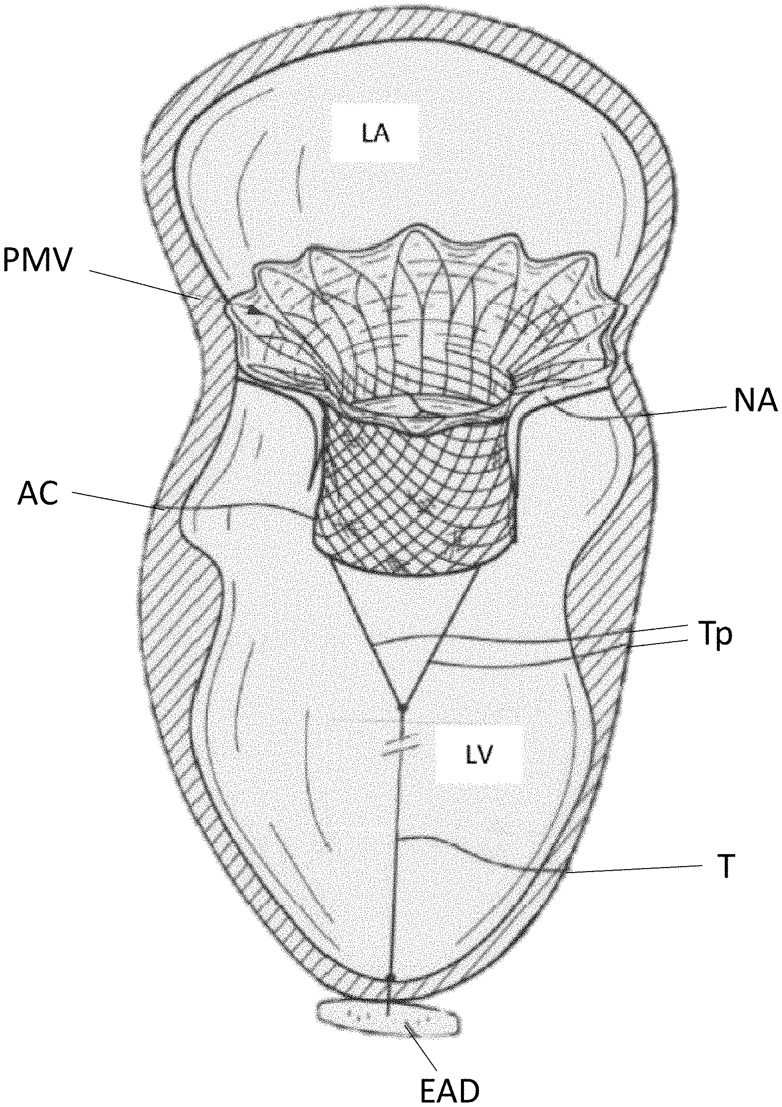
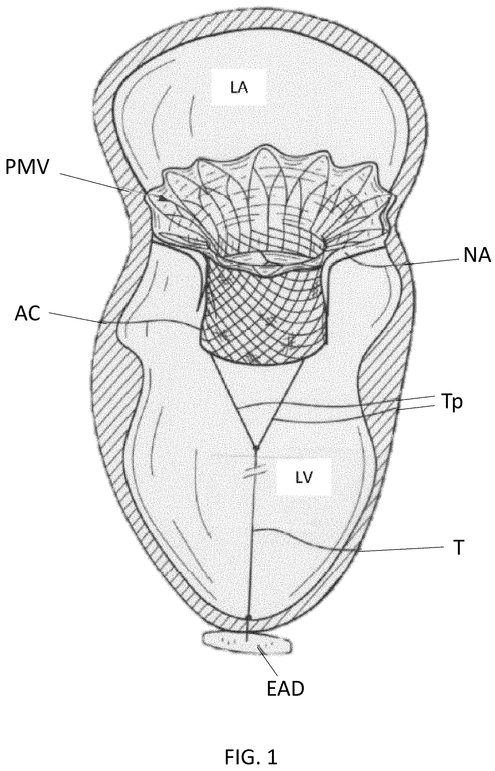
[0006] FIG. 1 is a cross-sectional illustration of portion of a heart with a prosthetic mitral valve implanted therein and an epicardial anchor device anchoring the mitral valve in position.
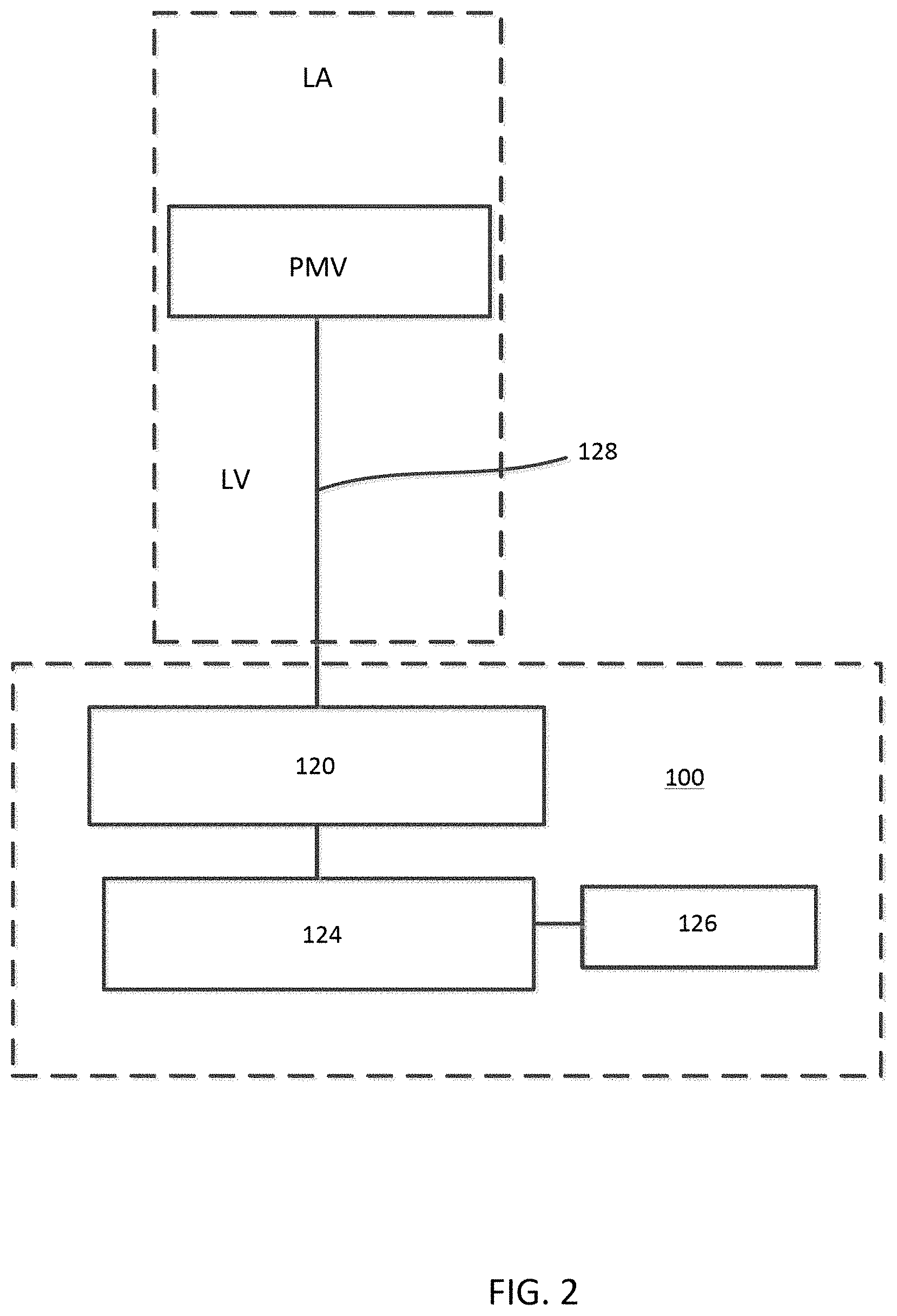
[0007] FIG. 2 is a schematic illustration of an epicardial anchor device, according to an embodiment.
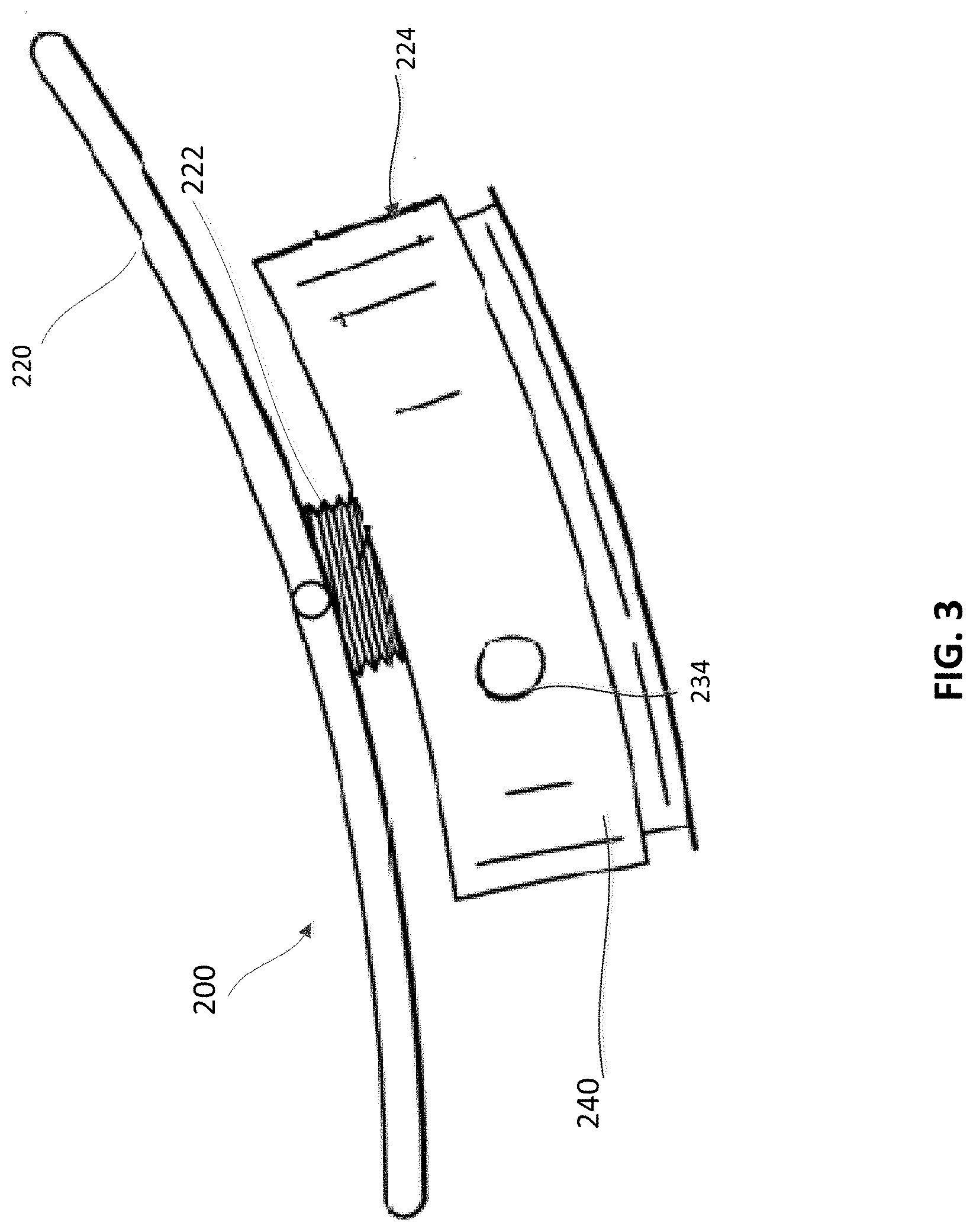
[0008] FIG. 3 is a side view of an epicardial anchor device, according to an embodiment.
[0009] FIG. 4 is an exploded side view of the epicardial anchor device of FIG. 3.
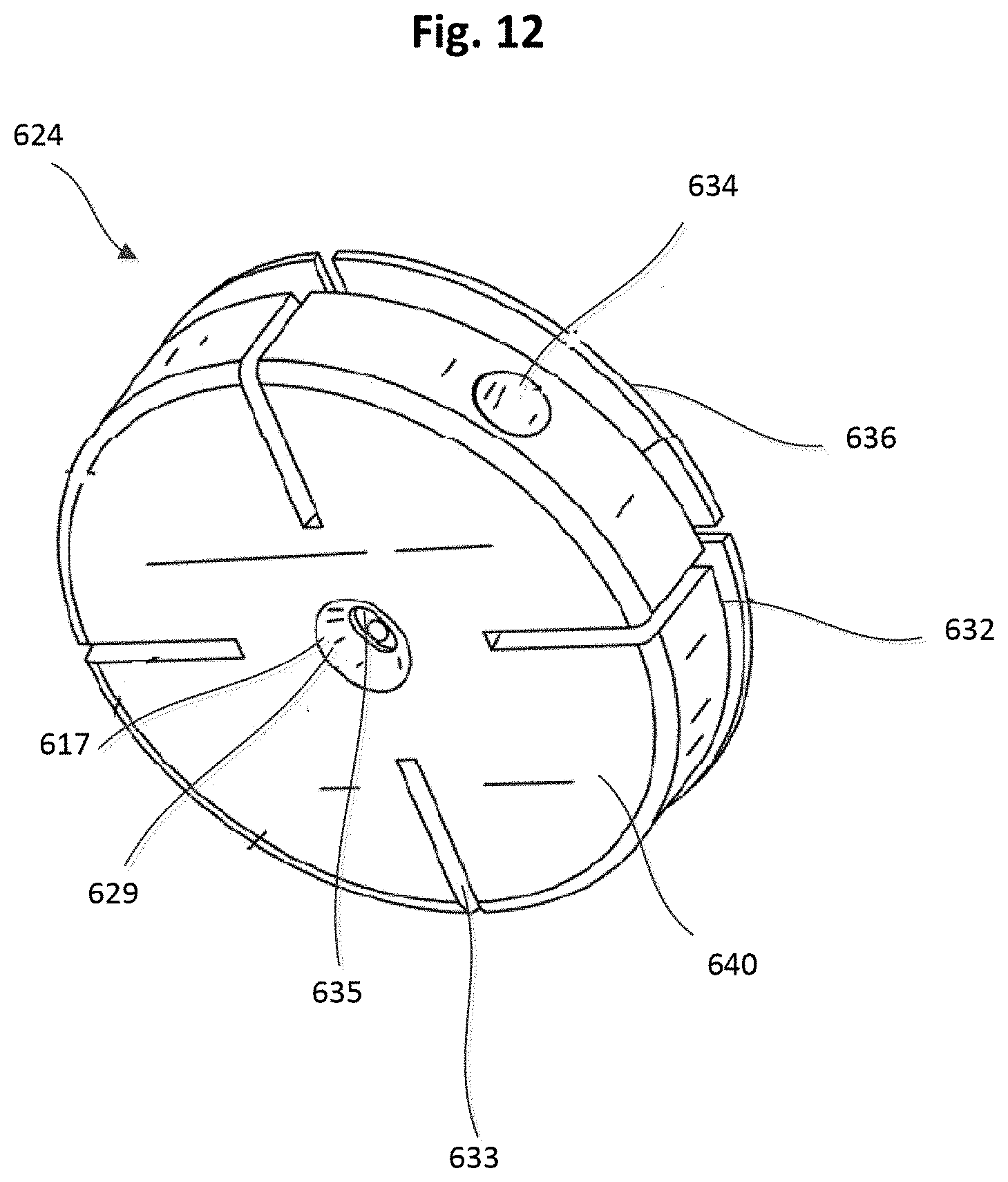
[0010] FIG. 5 is a side view of the epicardial anchor device of FIG. 3 shown disposed at a spaced distance from a puncture site in an epicardial surface of a ventricular wall and showing a sleeve gasket of the epicardial anchoring device in an uncompressed state or configuration.
[0011] FIG. 6 is a side view of the epicardial anchor device and ventricular wall of FIG. 5, shown with the anchoring device compressed against the puncture site and ventricular wall and the gasket in a compressed state or configuration.
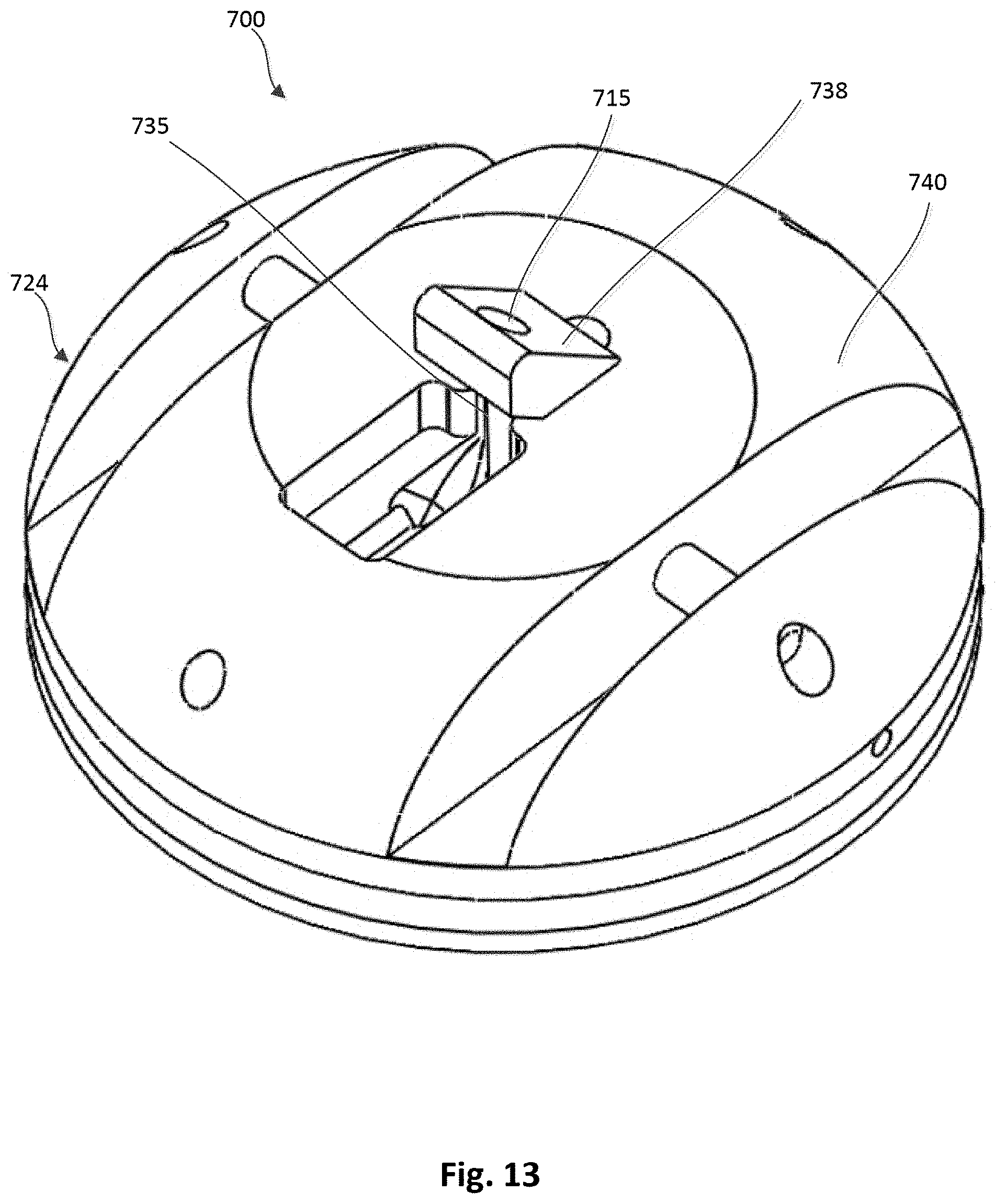
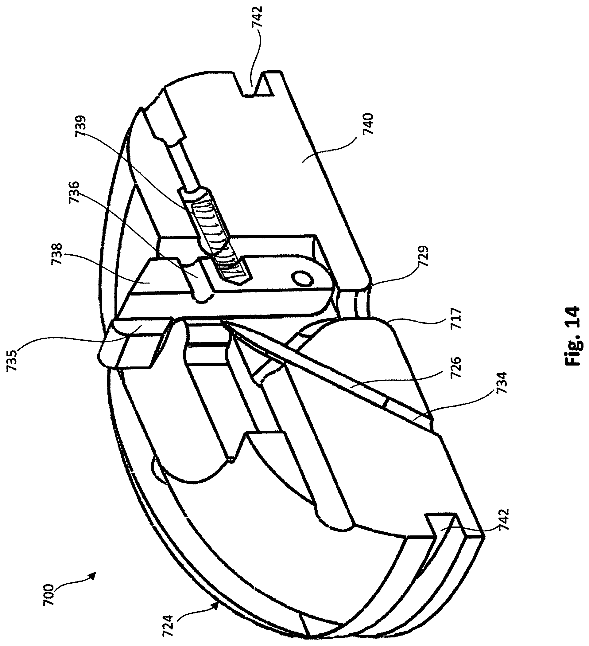
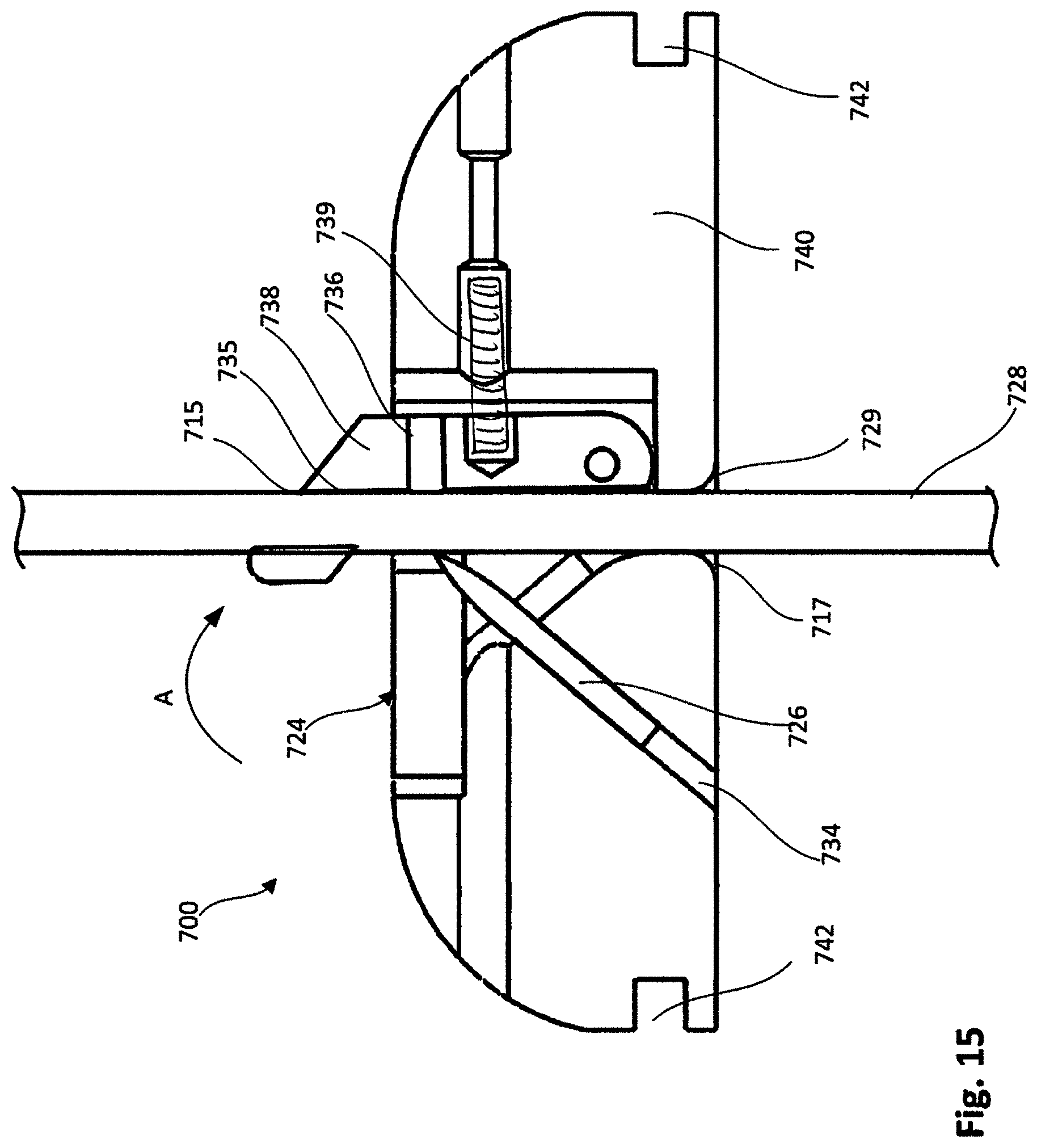
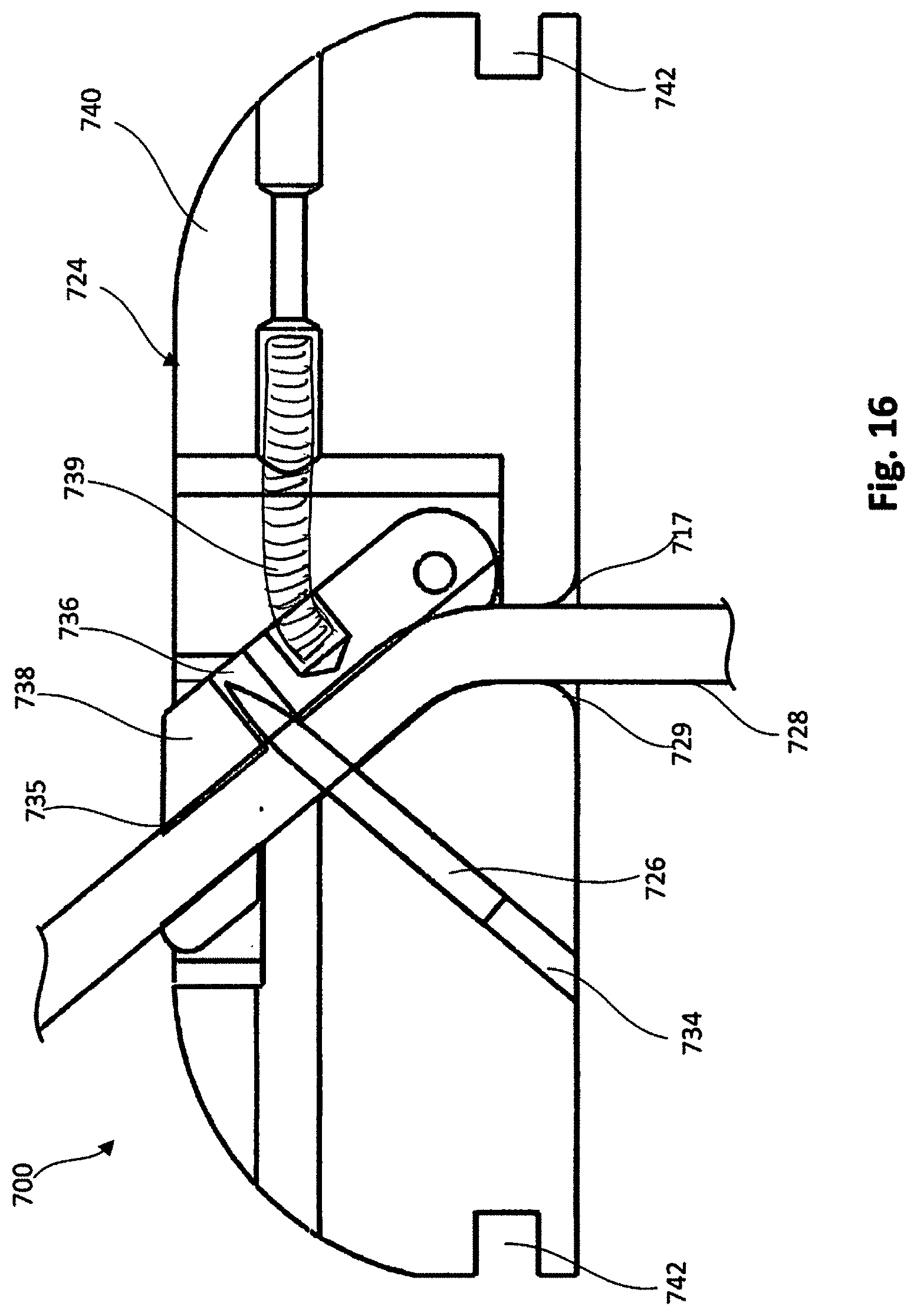
[0012] FIG. 7 is an exploded side view of an epicardial anchor device, according to another embodiment.
[0013] FIG. 8 is an exploded side view of an epicardial anchor device, according to another embodiment.
[0014] FIG. 9 is a top view of a flexible pad that can be included in an epicardial anchor device, according to an embodiment.
[0015] FIG. 10 is a perspective view of the flexible pad of FIG. 9 and a portion of a tether disposed therethrough.
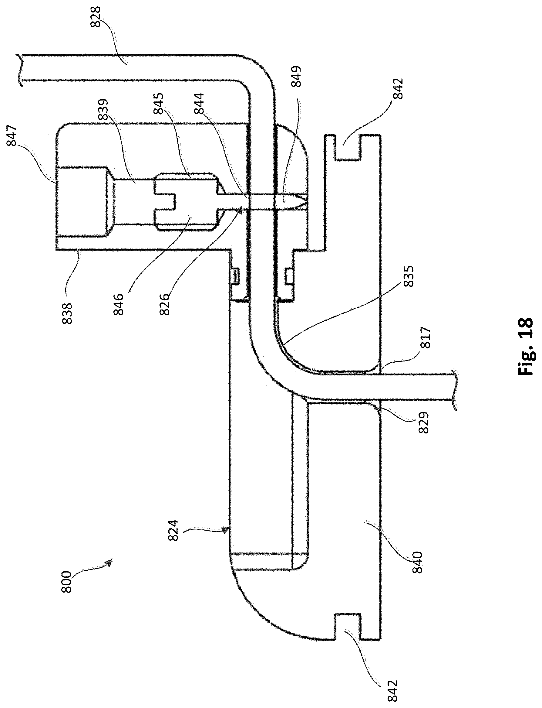
[0016] FIG. 11 is a perspective view of a locking pin and a tether attachment member, according to an embodiment.
[0017] FIG. 12 is a bottom perspective view of the tether attachment member of FIG. 11.
[0018] FIG. 13 is a top perspective view of a tether attachment member that can be used within an anchor device, according to an embodiment, with a lever arm shown in a first position.
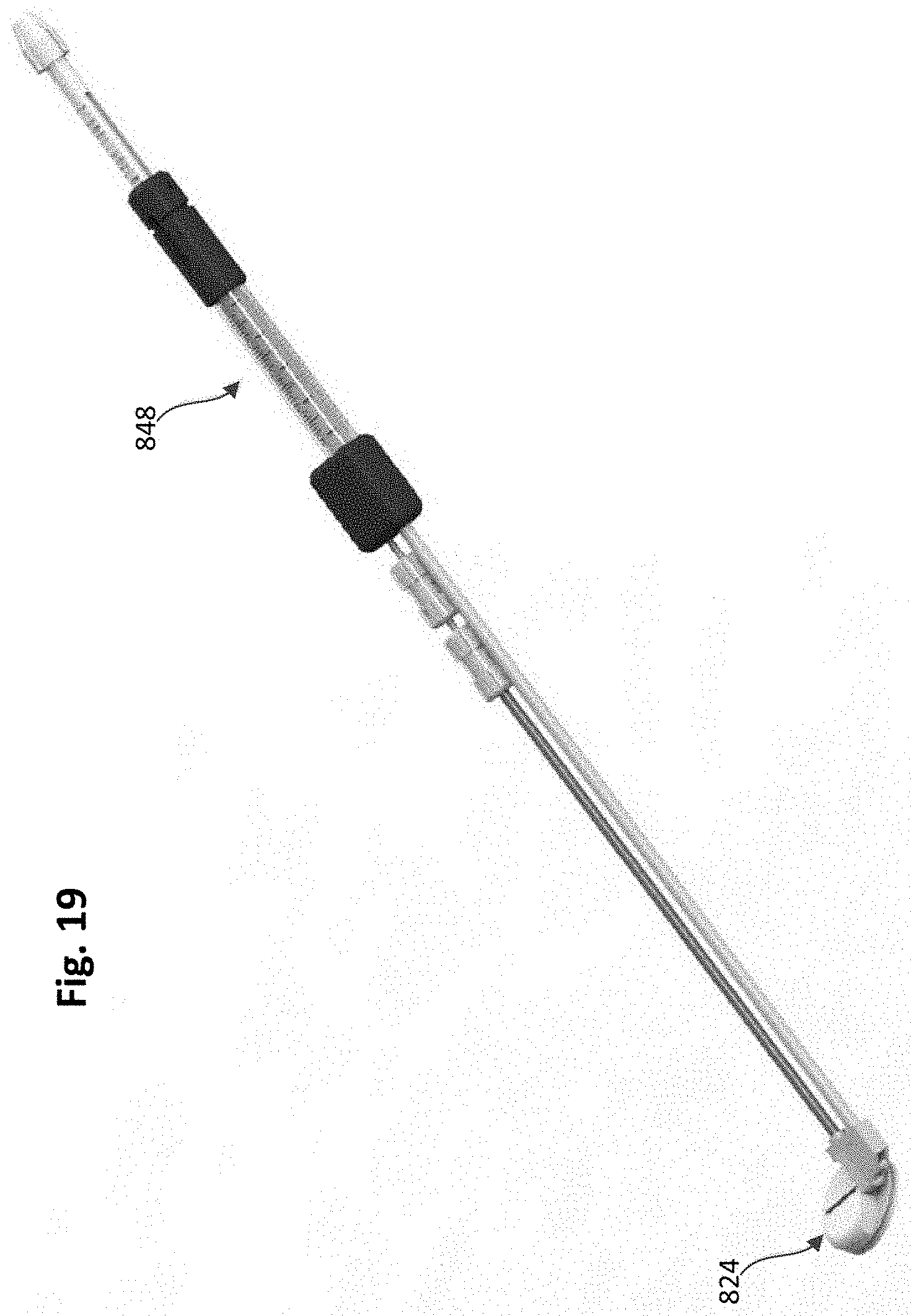
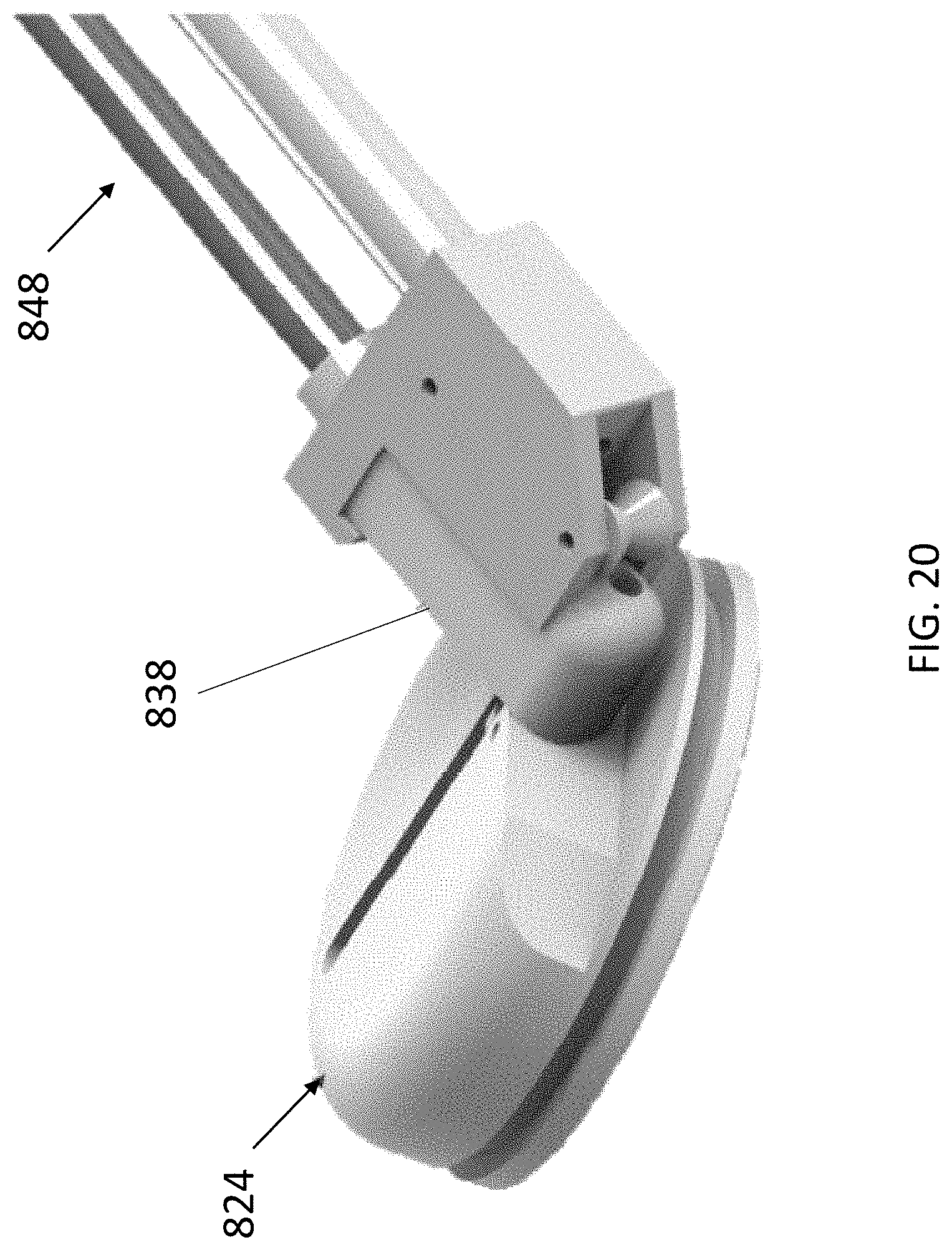
[0019] FIG. 14 is a cross-sectional perspective view of the tether attachment member of FIG. 13 with the lever arm shown in the first position.
[0020] FIG. 15 is a cross-sectional side view of the tether attachment member of FIG. 13 with the lever arm shown in the first position and a portion of a tether extending through the device.
[0021] FIG. 16 is a cross-sectional side view of the tether attachment member of FIG. 13 with the lever arm shown in a second position and a portion of a tether extending through the device.
[0022] FIG. 17 is a cross-sectional perspective view of a tether attachment member, according to an embodiment, with an access arm of the anchor device shown in a first position and a portion of a tether extending through the device.
[0023] FIG. 18 is a side-cross-sectional view of the tether attachment member of FIG. 17 shown with the access arm in the first position and the portion of a tether extending through the device.
[0024] FIG. 19 is a perspective view of the tether attachment member of FIG. 17 with a delivery device coupled thereto.
[0025] FIG. 20 is an enlarged view of the tether attachment member and a portion of the delivery device of FIG. 19.
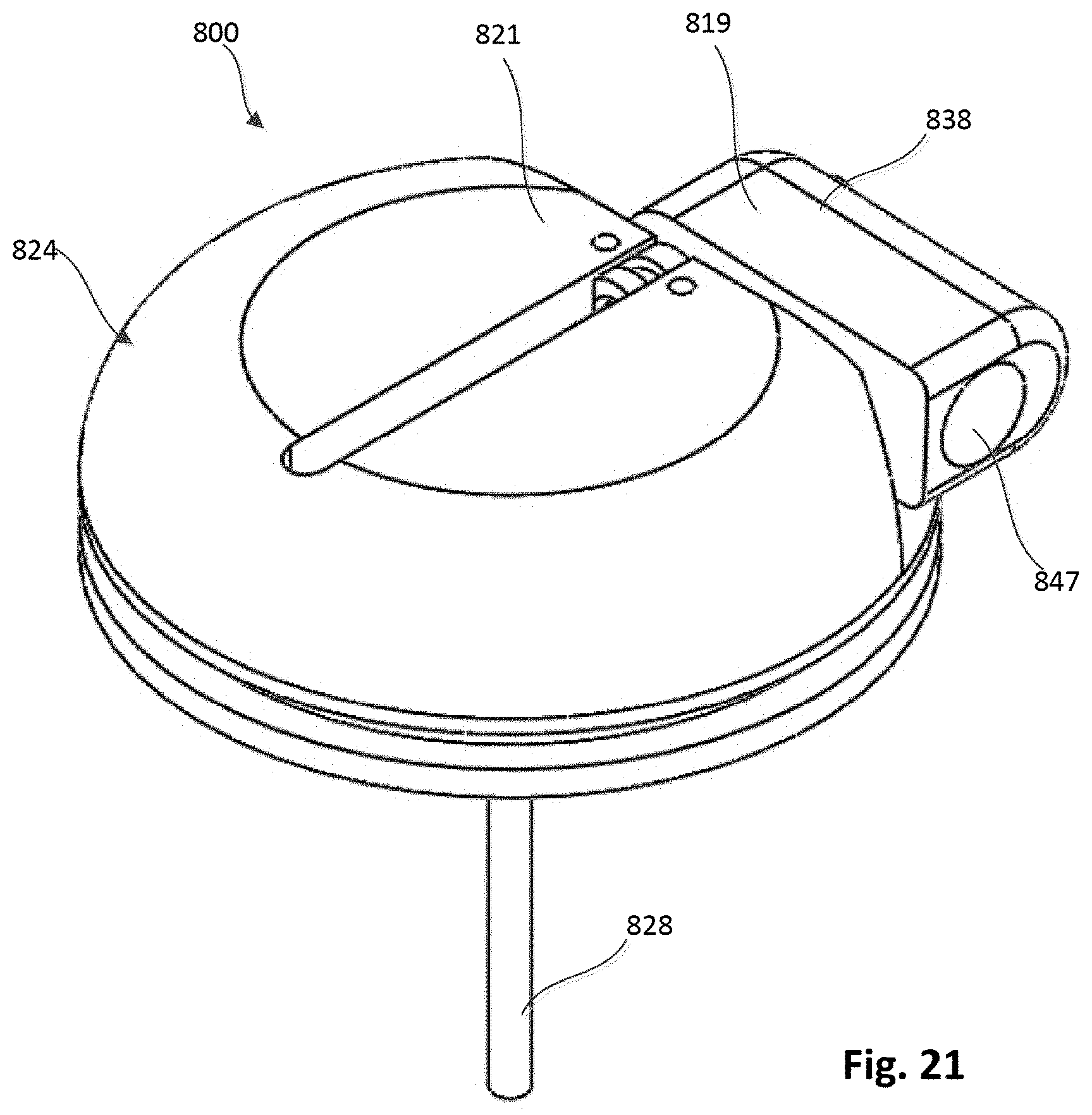
[0026] FIG. 21 is a top perspective view of the tether attachment member of FIG. 17 with the access arm shown in a second position.
[0027] FIG. 22 is a top perspective view of an epicardial anchor device, according to another embodiment.
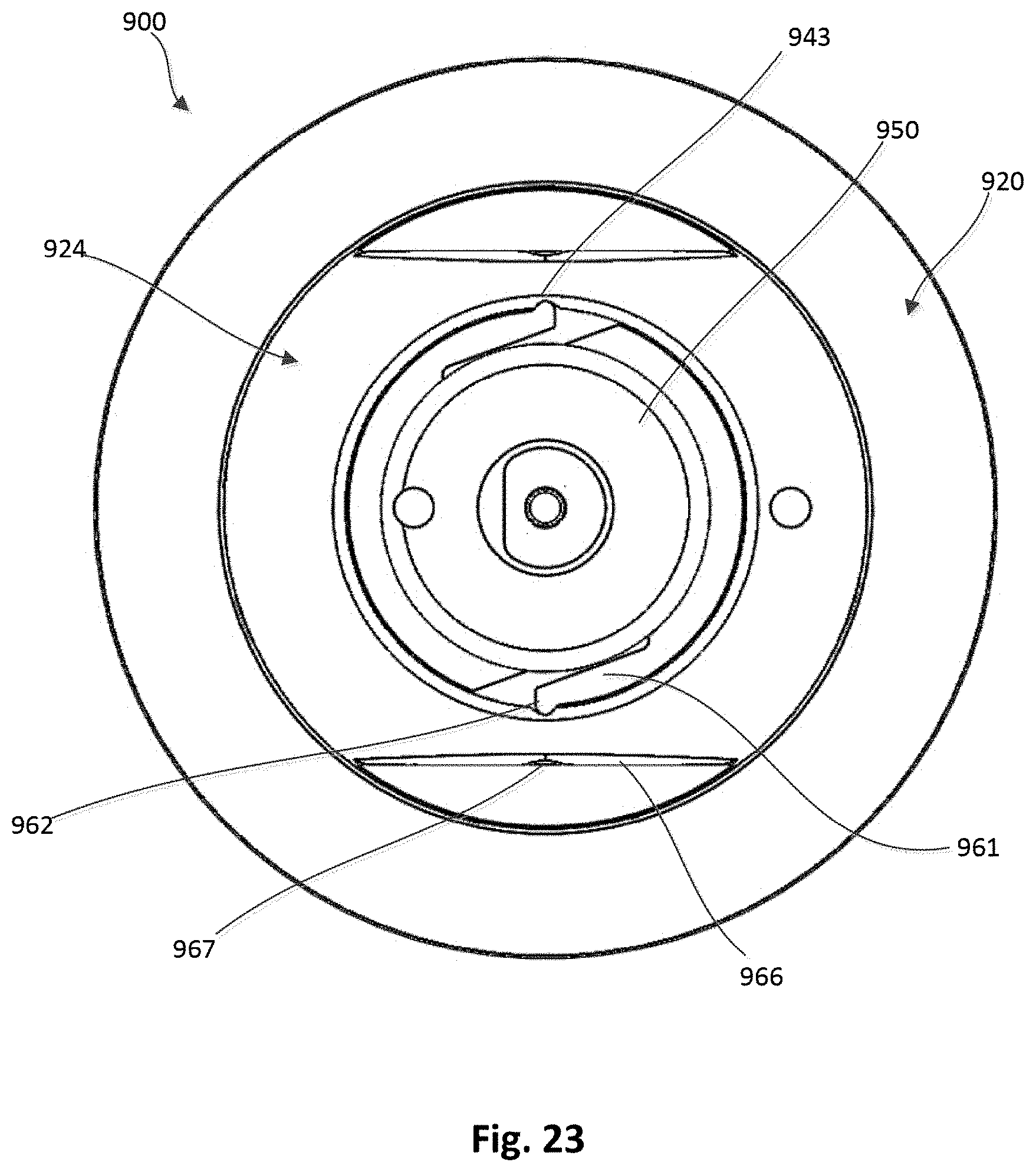
[0028] FIG. 23 is a top view of the epicardial anchor device of FIG. 22.
[0029] FIG. 24 is an exploded view of the epicardial anchor device of FIG. 22.
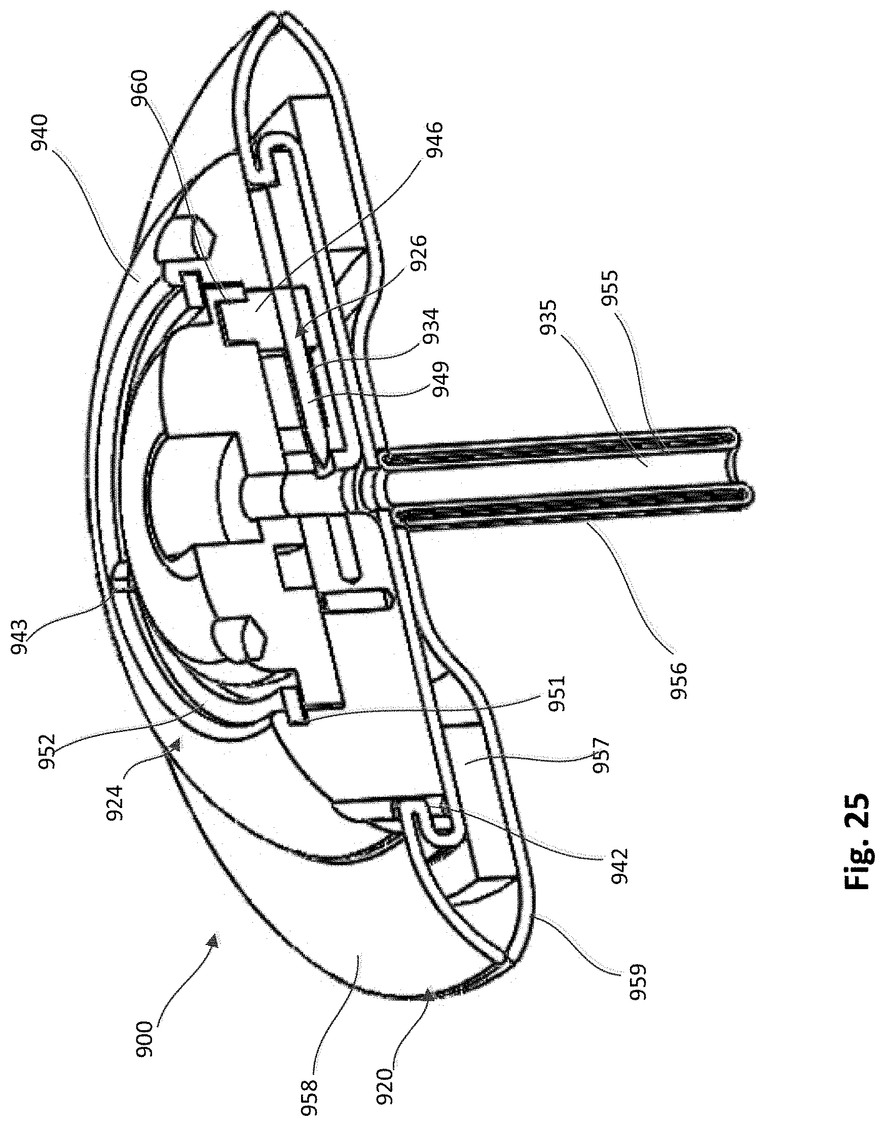
[0030] FIG. 25 is a cross-sectional perspective view of the epicardial anchor device of FIG. 22 with a locking pin of the device shown in a first position.
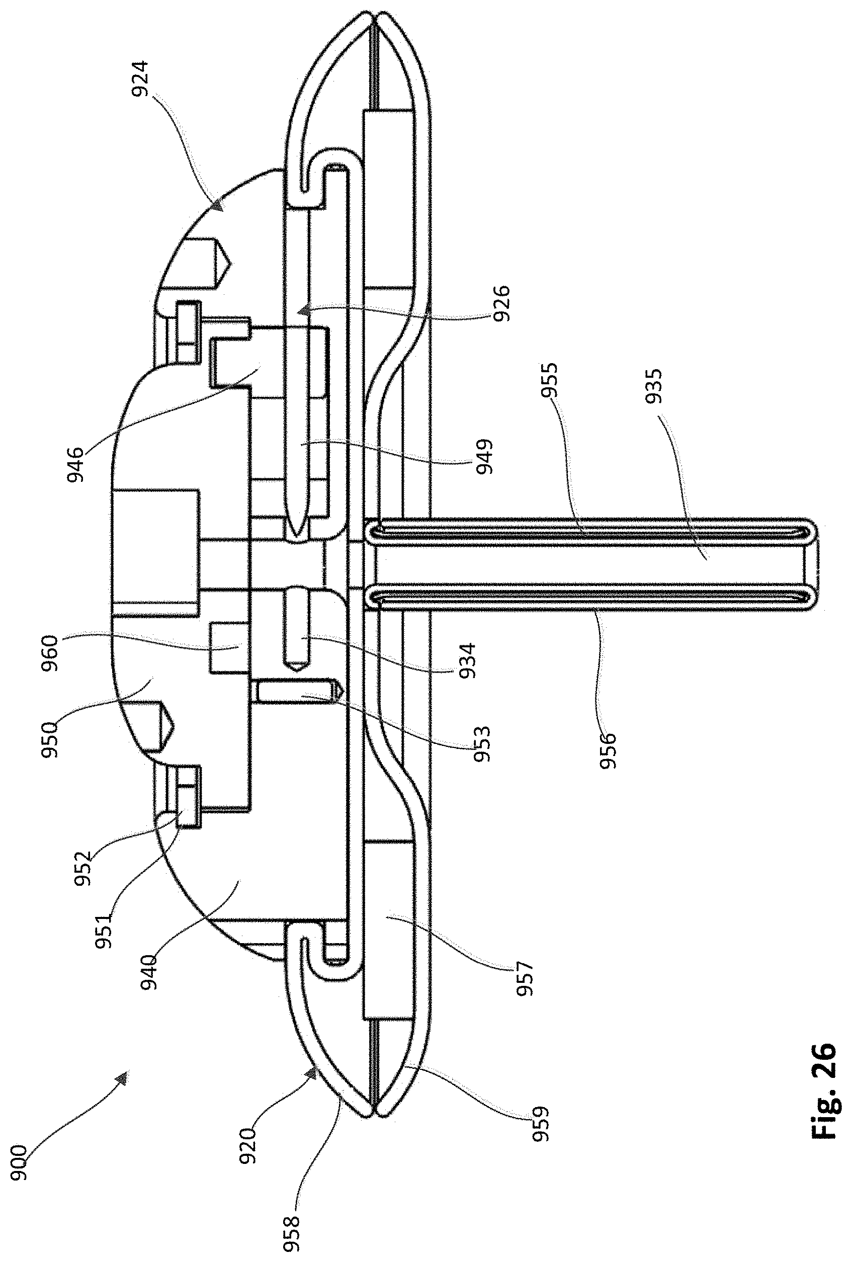
[0031] FIG. 26 is a cross-sectional side view of the epicardial anchor device of FIG. 20 with the locking pin of the device shown in the first position.
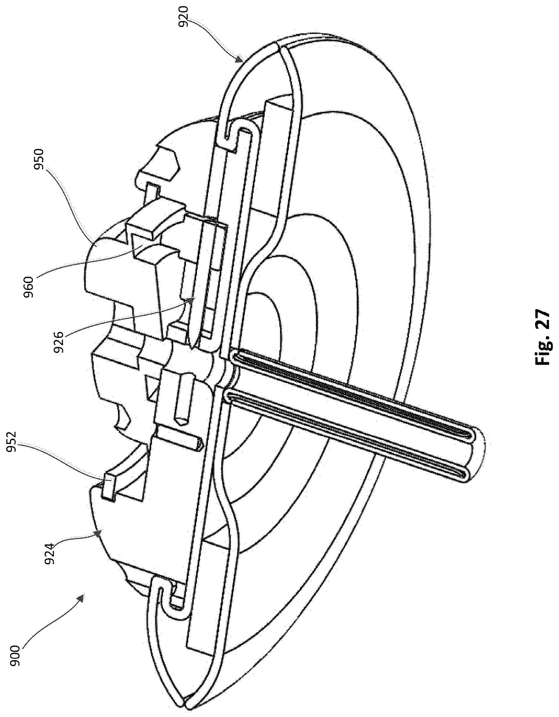
[0032] FIG. 27 is a cross-sectional bottom perspective view of the epicardial anchor device of FIG. 22 with the locking pin shown in a second position.
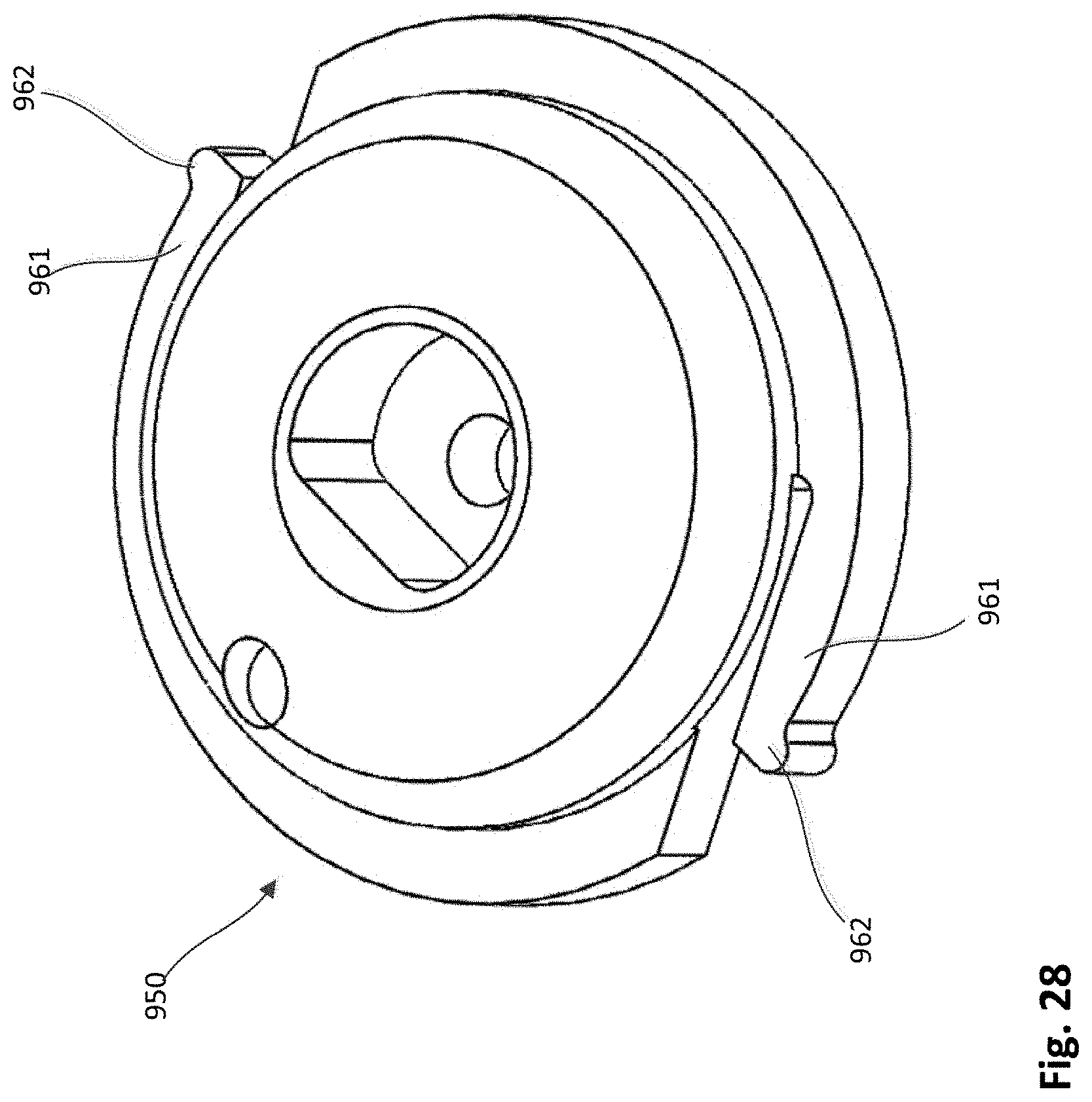
[0033] FIGS. 28 and 29 are a top perspective and a bottom perspective view, respectively, of a hub member of the epicardial anchor device of FIG. 22.
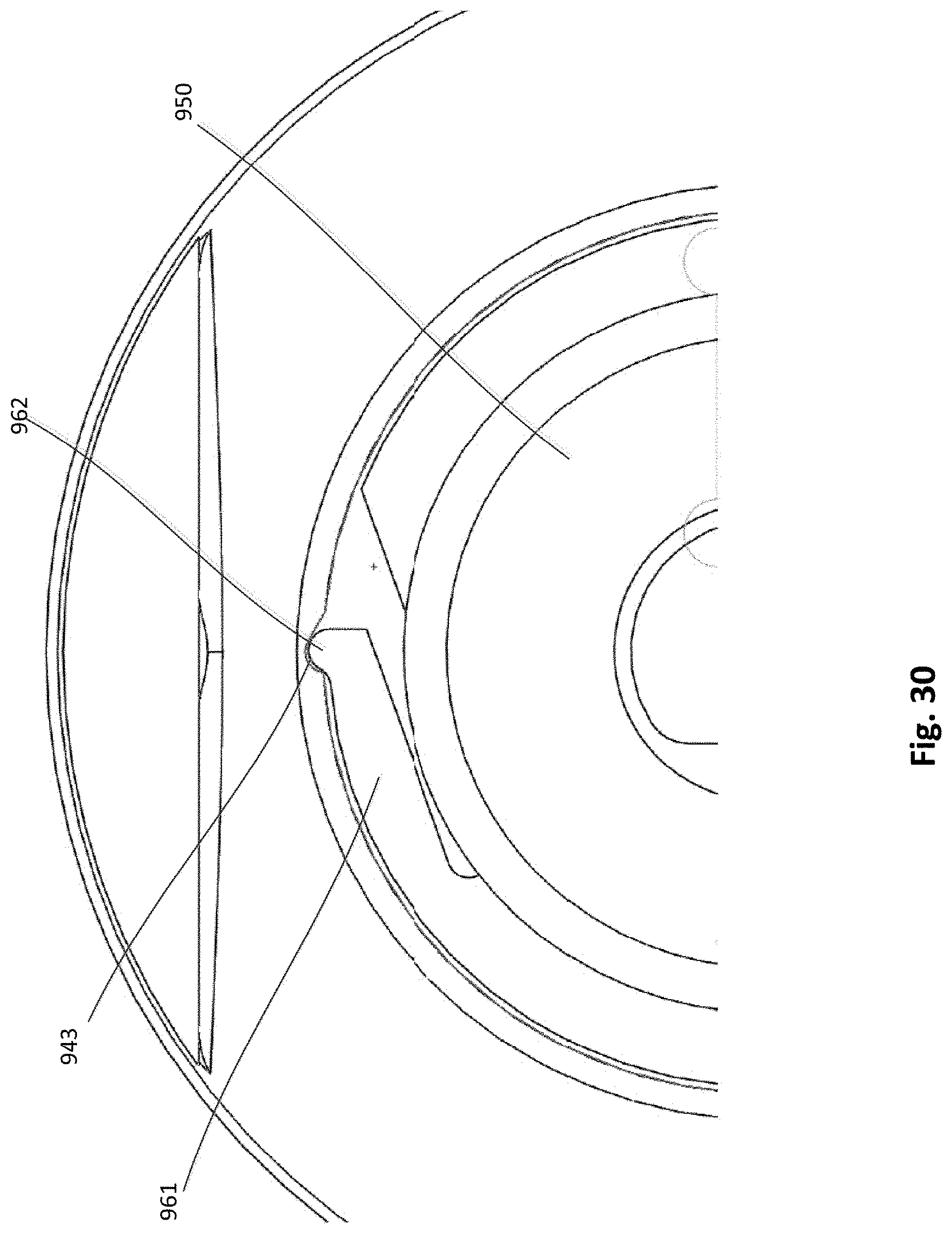
[0034] FIG. 30 is an enlarged top view of a portion of the pericardial pad device of FIG. 22.
[0035] FIG. 31 is a perspective view of the epicardial anchor device of FIG. 22 with a delivery device coupled thereto.
DETAILED DESCRIPTION
[0036] Apparatus and methods are described herein that can be used for securing and anchoring a prosthetic heart valve, such as, for example, a prosthetic mitral valve. Apparatus and methods described herein can also be used to close openings through the heart formed for example, when performing a procedure to implant a prosthetic heart valve. Apparatus and methods described herein can also be used to anchor other medical devices and/or to close punctures or openings in other body lumens formed during a diagnostic or therapeutic procedure.
[0037] In some embodiments, an apparatus includes a tether attachment member that includes a base member that defines at least a portion of a tether passageway through which a portion of a tether extending from a prosthetic heart valve can be received therethrough. The base member defines a locking pin channel that intersects the tether passageway. A locking pin is disposable within the locking pin channel and movable between a first position in which the locking pin is at a spaced distance from the tether passageway, and a second position in which the locking pin intersects the tether passageway and can engage the portion of a tether disposed therein to secure the tether to the tether attachment member.
[0038] In some embodiments, an apparatus includes a tether attachment member that includes a base member and a lever arm movably coupled to the base member. The base member and the lever arm collectively define a tether passageway through which a portion of a tether extending from a prosthetic heart valve can be received therethrough. The base member defines a locking pin channel that intersects the tether passageway and is in fluid communication therewith, and a locking pin is disposed within the locking pin channel. The lever arm is configured to be moved from a first position in which the portion of the tether can be inserted into the tether passageway, and a second position in which the locking pin secures a tether disposed within the tether passageway to the tether attachment member.
[0039] In some embodiments, an apparatus includes a tether attachment member that includes a base member and a hub member rotatably coupled to the base member. The base member and the hub each define at least a portion of a tether passageway through which a portion of a tether extending from a prosthetic heart valve can be received therethrough. The base member defines a locking pin channel that intersects the tether passageway and is in fluid communication therewith and a locking pin is disposed at least partially within the locking pin channel. The hub defines a cam channel in which a driver portion of the locking pin is received. The hub is configured to rotate relative to the base member such that the cam channel moves the locking pin linearly within the locking pin channel moving the locking pin from a first position in which the locking pin is at a spaced distance from the tether passageway, and a second position in which the locking pin intersects the tether passageway and engages a portion of a tether disposed therein to secure the tether to the tether attachment member.
[0040] In some embodiments, a method includes inserting into a tether passageway defined by a tether attachment member, a portion of a tether extending from a prosthetic heart valve. The tether attachment member is disposed adjacent an opening in a ventricular wall of a heart from which the tether extends. The tether attachment member is actuated such that a locking pin disposed within a locking pin channel defined by the tether attachment member intersects the tether passageway and engages a portion of the tether disposed within the tether passageway, securing the tether to the tether attachment member.
[0041] As used in this specification, the singular forms "a," "an" and "the" include plural referents unless the context clearly dictates otherwise. Thus, for example, the term "a member" is intended to mean a single member or a combination of members, "a material" is intended to mean one or more materials, or a combination thereof.
[0042] As used herein, the words "proximal" and "distal" refer to a direction closer to and away from, respectively, an operator of, for example, a medical device. Thus, for example, the end of the medical device closest to the patient's body (e.g., contacting the patient's body or disposed within the patient's body) would be the distal end of the medical device, while the end opposite the distal end and closest to, for example, the user (or hand of the user) of the medical device, would be the proximal end of the medical device.
[0043] In some embodiments, an epicardial pad system is described herein that can be used to anchor a compressible prosthetic heart valve replacement (e.g., a prosthetic mitral valve), which can be deployed into a closed beating heart using a transcatheter delivery system. Such an adjustable-tether and epicardial pad system can be deployed via a minimally invasive procedure such as, for example, a procedure utilizing the intercostal or subxyphoid space for valve introduction. In such a procedure, the prosthetic valve can be formed in such a manner that it can be compressed to fit within a delivery system and secondarily ejected from the delivery system into the target location, for example, the mitral or tricuspid valve annulus.
[0044] A compressible prosthetic mitral valve can have a shape, for example that features a tubular stent body that contains leaflets and an atrial cuff. This allows the valve to seat within the mitral annulus and be held by the native mitral leaflets. The use of a flexible valve attached using an apical tether can provide compliance with the motion and geometry of the heart. The geometry and motion of the heart are well-known as exhibiting a complicated biphasic left ventricular deformation with muscle thickening and a sequential twisting motion. The additional use of the apically secured ventricular tether helps maintain the prosthetic valve's annular position without allowing the valve to migrate, while providing enough tension between the cuff and the atrial trabeculations to reduce, and preferably eliminate, perivalvular leaking. The use of a compliant valve prosthesis and the special shape and features can help reduce or eliminate clotting and hemodynamic issues, including left ventricular outflow tract (LVOT) interference problems. Many known valves are not able to address problems with blood flow and aorta/aortic valve compression issues.
[0045] Structurally, the prosthetic heart valve can include: a self-expanding tubular frame having a cuff at one end (the atrial end); one or more attachment points to which one or more tethers can be attached, preferably at or near the ventricular end of the valve; and a leaflet assembly that contains the valve leaflets, which can be formed from stabilized tissue or other suitable biological or synthetic material. In one embodiment, the leaflet assembly may include a wire form where a formed wire structure is used in conjunction with stabilized tissue to create a leaflet support structure, which can have anywhere from 1, 2, 3 or 4 leaflets, or valve cusps disposed therein. In another embodiment, the leaflet assembly can be wireless and use only the stabilized tissue and stent body to provide the leaflet support structure, and which can also have anywhere from 1, 2, 3 or 4 leaflets, or valve cusps disposed therein.
[0046] The upper cuff portion may be formed by heat-forming a portion of a tubular nitinol structure (formed from, for example, braided wire or a laser-cut tube) such that the lower portion retains the tubular shape but the upper portion is opened out of the tubular shape and expanded to create a widened collar structure that may be shaped in a variety of functional regular or irregular funnel-like or collar-like shapes.
[0047] A prosthetic mitral valve can be anchored to the heart at a location external to the heart via one or more tethers coupled to an anchor device, as described herein. For example, the tether(s) can be coupled to the prosthetic mitral valve and extend out of the heart and be secured at an exterior location (e.g., the epicardial surface) with an anchor device, as described herein. An anchor device as described herein can be used with one or more such tethers in other surgical situations where such a tether may be desired to extend from an intraluminal cavity to an external anchoring site.
[0048] FIG. 1 is a cross-sectional illustration of the left ventricle LV and left atrium LA of a heart having a transcatheter prosthetic mitral valve PMV deployed therein and an epicardial anchor device EAD as described herein securing the prosthetic mitral valve PMV in place. FIG. 1 illustrates the prosthetic mitral valve PMV seated into the native valve annulus and held there using an atrial cuff AC of the prosthetic mitral valve PMV, the radial tension from the native leaflets, and a ventricular tether T secured with attachment portions Tp to the prosthetic mitral valve PMV and to the epicardial anchor EAD. Various embodiments of an epicardial anchor device are described in more detail below with reference to specific embodiments.
[0049] FIG. 2 is a schematic illustration of an epicardial anchor device 100 (also referred to herein as "anchor device" or "epicardial anchor") according to an embodiment. The anchor device 100 can be used to anchor or secure a prosthetic mitral valve PMV deployed between the left atrium and left ventricle of a heart. The anchor device 100 can be used, for example, to anchor or secure the prosthetic mitral valve PMV via a suturing tether 128 as described above with respect to FIG. 1. The anchor device 100 can also seal a puncture formed in the ventricular wall (not shown in FIG. 2) of the heart during implantation of the prosthetic mitral valve PMV. The anchor device 100 can also be used in other applications to anchor a medical device (such as any prosthetic atrioventricular valve or other heart valve) and/or to seal an opening such as a puncture.
[0050] The anchor device 100 can include a pad (or pad assembly) 120, a tether attachment member 124 and a locking pin 126. In some embodiments, the anchor device 100 can include a sleeve gasket (not shown in FIG. 2) as described with respect to FIGS. 3-6. The pad 120 can contact the epicardial surface of the heart and can be constructed of any suitable biocompatible surgical material. The pad 120 can be used to assist the sealing of a surgical puncture formed when implanting a prosthetic mitral valve. In some embodiments, the pad 120 can include a slot that extends radially to an edge of the pad 120 such that the pad 120 can be attached to, or disposed about, the tether 128 by sliding the pad 120 onto the tether 128 via the slot. Such an embodiment is described below with respect to FIGS. 9 and 10.
[0051] In some embodiments, the pad 120 can be made with a double velour material to promote ingrowth of the pad 120 into the puncture site area. For example, pad or felt pledgets can be made of a felted polyester and may be cut to any suitable size or shape, such as those available from Bard.RTM. as PTFE Felt Pledgets having a nominal thickness of 2.87 mm. In some embodiments, the pad 120 can be larger in diameter than the tether attachment member 124. The pad 120 can have a circular or disk shape, or other suitable shapes.
[0052] The tether attachment member 124 can provide the anchoring and mounting platform to which one or more tethers 128 can be coupled (e.g., tied or pinned). The tether attachment member 124 can include a base member (not shown) that defines at least a portion of a tether passageway (not shown) through which the tether 128 can be received and pass through the tether attachment member 124, and a locking pin channel (not shown) through which the locking pin 126 can be received. The locking pin channel can be in fluid communication with the tether passageway such that when the locking pin 126 is disposed in the locking pin channel, the locking pin 126 can contact or pierce the tether 128 as it passes through the tether passageway as described in more detail below with reference to specific embodiments.
[0053] The locking pin 126 can be used to hold the tether 128 in place after the anchor device 100 has been tightened against the ventricular wall and the tether 128 has been pulled to a desired tension. For example, the tether 128 can extend through a hole in the pad 120, through a hole in a sleeve gasket (if the anchor device includes a sleeve gasket), and through the tether passageway of the tether attachment member 124. The locking pin 126 can be inserted or moved within the locking pin channel 134 such that it pierces or otherwise engages the tether 128 as the tether 128 extends through the tether passageway of the tether attachment member 124. Thus, the locking pin 126 can intersect the tether 128 and secure the tether 128 to the tether attachment member 124.
[0054] The tether attachment member 124 can be formed with, a variety of suitable biocompatible material. For example, in some embodiments, the tether attachment member 124 can be made of polyethylene, or other hard or semi-hard polymer, and can be covered with a polyester velour to promote ingrowth. In other embodiments, the tether attachment member 124 can be made of metal, such as, for example, Nitinol.RTM., or ceramic materials. The tether attachment member 124 can be various sizes and/or shapes. For example, the tether attachment member 124 can be substantially disk shaped.
[0055] In some embodiments the tether attachment member 124 can include a lever arm (not shown in FIG. 2) that can be moved between an open position to load the tether 128 within the tether attachment member 124, and a closed position to secure the tether 128 to the tether attachment member 124. For example, in some embodiments, when the lever arm is moved to the closed position, the tether passageway is brought into an intersecting relation with the locking pin channel such that the locking pin 126 engages the tether 128 disposed within the tether passageway. In some embodiments, when the lever arm is in the open position, a tool can be used to move the locking pin within the locking pin channel such that the locking pin engages the tether 128 disposed within the tether passageway. In such an embodiment, after the locking pin 126 secures the tether 128, the lever arm can be moved to the closed position.
[0056] In some embodiments, the tether attachment member 124 can include a hub that is movably coupled to the base member of tether attachment member 124. The hub can define a channel that can receive a portion of the locking pin (or locking pin assembly) 126 such that as the hub is rotated, the hub acts as a cam to move the locking pin 126 linearly within the locking pin channel. As with previous embodiments, as the locking pin 126 is moved within the locking pin channel, the locking pin can engage or pierce the tether 128 disposed within the tether passageway and secure the tether 128 to the tether attachment member 124. Such an embodiment is described herein with respect to FIGS. 22-31.
[0057] In use, after a PMV has been placed within a heart, the tether extending from the PMV can be inserted into the tether passageway of the anchor device 100 and the tension on the tether attachment device can be adjusted to a desired tension. Alternatively, in some cases, the tether extending from the PMV can be coupled to the anchor device 100 prior to the PMV being placed within the heart. The anchor device 100 (e.g., some portion of the anchor device such as the tether attachment member 124, or the lever arm or hub depending on the particular embodiment) can be actuated such that the locking pin 126 intersects the tether passageway and engages a portion of the tether disposed within the tether passageway, securing the tether to the tether attachment member. In some embodiments, prior to inserting the tether into the tether passageway, the anchor device 100 can be actuated to configure the anchor device 100 to receive the tether. For example, if the tether attachment member includes a lever arm movably coupled to the base member, the lever arm may need to be moved to an open position to allow the tether to be inserted. In some embodiments, the anchor device 100 can be actuated by rotating a hub relative to a base member of the tether attachment member 124 such that the locking pin 126 is moved from a first position in which the locking pin is spaced from the tether passageway and a second position in which the locking pin intersects the tether passageway and engages or pierces the portion of the tether.
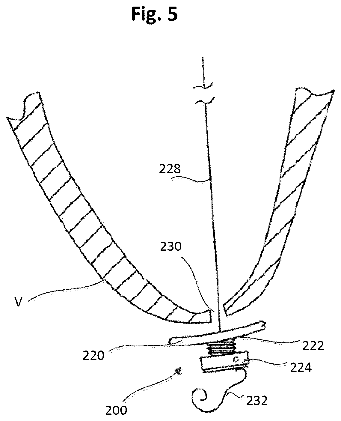
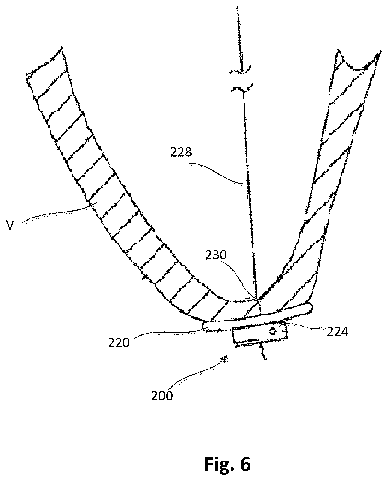
[0058] One implementation of the epicardial anchor device 100 is shown in FIGS. 3-6. An epicardial anchor device 200 (also referred to herein as "anchor device" or "epicardial anchor") can include a flexible pad 220, a sleeve gasket 222, a tether attachment member 224 and a locking pin 226 (shown in FIG. 4). The anchor device 200 can be used to anchor or secure a prosthetic mitral valve (not shown in FIGS. 3-6) via a suturing tether 228 shown in FIGS. 5 and 6. The anchor device 200 can also seal a puncture 230 formed in the ventricular wall V (see FIGS. 5 and 6) of the heart during implantation of the prosthetic mitral valve.
[0059] The flexible pad 220 (also referred to herein as "pad") can contact the epicardial surface of the heart and can be constructed of any suitable biocompatible surgical material. The pad 220 can be used to assist the sealing of a surgical puncture (e.g., puncture 230) formed when implanting a prosthetic mitral valve. The pad 220 can be made with the same or similar materials as described above for pad 120, and can be various sizes and shapes. The pad 220 is shown as having a circular or disk shape, however it should be understood that other suitable shapes can alternatively be used. The pad 220 defines a hole 225 (see FIGS. 4 and 6) through which the tether 228 (shown in FIGS. 5 and 6) can be received as described in more detail below.
[0060] The sleeve gasket 222 can be disposed between the pad 220 and the tether attachment member 224 and can be used to seal a gap or leakage that may occur between the pad 220 and the tether attachment member 224. The sleeve gasket 222 can be made of, for example, a flexible material such that it can be compressed when the tether attachment member 224 and/or pad 220 are tightened against the puncture site, e.g. against the ventricular wall. The sleeve gasket 222 may be a separate component coupled to the pad 220 and the tether attachment member 224 or can be formed integrally or monolithically with the pad 220 and/or the tether attachment member 224. The sleeve gasket 222 can be used to prevent hemodynamic leakage that may flow along the path of the suturing tether 228. The sleeve gasket 222 can also define a hole (not shown) through which the tether 228 can be received.
[0061] The tether attachment member 224 can provide the anchoring and mounting platform to which one or more tethers 228 (see FIGS. 5 and 6) may be coupled (e.g., tied). The tether attachment member 224 includes a base member 240 that defines an axial tether passageway 235 through which the tether 228 can be received and pass through the tether attachment member 224, and a locking pin channel 234 through which the locking pin 226 can be received. The locking pin channel 234 can be in fluid communication with the tether passageway 235 such that when the locking pin 226 is disposed in the locking pin channel 234, the locking pin 226 can contact the tether 228 as it passes through the tether passageway 235 as described in more detail below. The locking pin 226 can be used to hold the tether 228 in place after the anchor device 200 has been tightened against the ventricular wall V. For example, the tether 228 can extend through the hole 225 of the pad 220, through the hole (not shown) of the sleeve gasket 222, and through the tether passageway 235 of the tether attachment member 224. The locking pin 226 can be inserted through the locking pin channel 234 such that it pierces the tether 228 as the tether 228 extends through the tether passageway 235 of the tether attachment member 224. Thus, the locking pin 226 can laterally intersect the tether 228 and secure the tether 228 to the tether attachment member 224.
[0062] The tether attachment member 224 can be made of any suitable biocompatible material. For example, in some embodiments, the tether attachment member 224 can be made of polyethylene, or other hard or semi-hard polymer, and can be covered with a polyester velour to promote ingrowth. In other embodiments, the tether attachment member 224 can be made of metal, such as, for example, Nitinol.RTM., or ceramic materials. The tether attachment member 224 can be various sizes and/or shapes. For example, the tether attachment member 224 can be substantially disk shaped.
[0063] In some embodiments, the tether attachment member 224 can be substantially disk shaped and have a diameter between, for example, 1.0-3.0 cm. In other embodiments, the tether attachment member 224 can have a diameter, for example, between 0.2-5.0 cm. For example, a larger size tether attachment member 224 may be desirable to use in, for example, a hernia repair, gastrointestinal repairs, etc.
[0064] The disk shape of the tether attachment member 224 used to capture and anchor a suture can also be used with little or no trauma to the tissue at the site of the anchor, unlike suture anchors that bore into tissue with screws or barbs. Further, the disk shaped tether attachment member 224 can be easily and quickly slid over the tether 228, instead of using stitches, which can allow for the effective permanent closure of large punctures. Surgically closing large punctures by sewing can be time consuming and difficult. When closing a puncture in the heart, adding the difficulty of requiring a surgeon to sew the puncture closed can increase the likelihood of life threatening complications to the patient. This is especially so in a situation where a prosthetic heart valve is delivered and deployed without opening the chest cavity using transcatheter technologies. Sewing a ventricular puncture closed in this situation may be undesirable.
[0065] FIGS. 5 and 6 illustrate the tether 228 extending through the puncture site 230 within a left ventricular wall V of a heart and coupled to the anchor device 200. FIG. 5 illustrates the anchor device 200 prior to being tightened against the epicardial surface of the ventricular wall V, and the sleeve gasket 222 in an uncompressed state or configuration. The tether 228 can optionally be wound around the tether attachment member 224 to further improve anchoring.
[0066] FIG. 6 illustrates the anchor device 200 tightened against the epicardial surface of the ventricular wall V. As shown in FIG. 6, the anchor device 200 can be compressed against the puncture site 230 and contact the epicardial surface. An end portion 232 (shown in FIG. 5) of the tether 228 can be trimmed after the tether 228 has been secured to the tether attachment member 224 or after the anchor device 200 has been secured against the epicardial surface.
[0067] FIG. 7 illustrates an embodiment of an epicardial anchor device 300 (also referred to herein as "anchor device" or "epicardial anchor") that is similar to the anchor device 200 except the anchor device 300 does not include a sleeve gasket (e.g., sleeve gasket 222 described above). The anchor device 300 can include a flexible pad 320, a tether attachment member 324 and a locking pin 326, which can be configured the same as or similar to the flexible pad 220, the tether attachment member 224 and the locking pin 226, respectively, described above. The anchor device 300 can be used the same as or similar to anchor device 200 to secure a prosthetic mitral valve (not shown) via a suturing tether (not shown). The anchor device 300 may be desirable to use, for example, when an anti-leakage sleeve is unnecessary to prevent hemodynamic leakage that may flow along the path of the suturing tether.
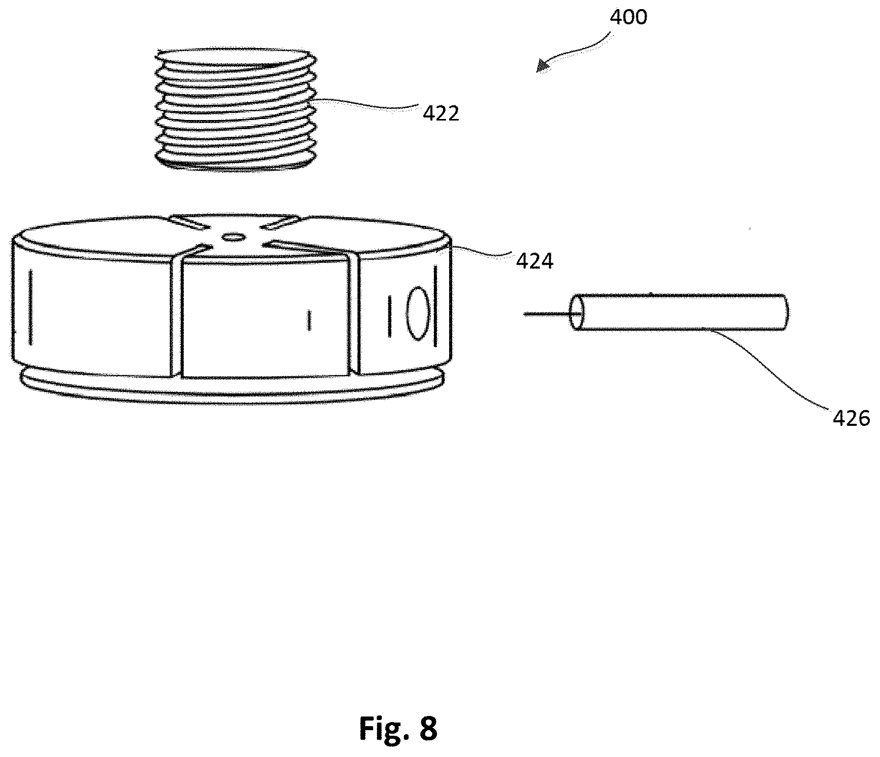
[0068] FIG. 8 illustrates an embodiment of an epicardial anchor device 400 (also referred to herein as "anchor device" or "epicardial anchor") that is similar to the anchor device 200 and the anchor device 300 except the anchor device 400 does not include a pad (e.g., pads 220 and 320). The anchor device 400 can include a tether attachment member 424, a sleeve gasket 422 and a locking pin 426, which can be configured the same as or similar to the tether attachment member 224, the sleeve gasket 222 and the locking pin 226, respectively, described above. The anchor device 400 can be used to anchor or secure a prosthetic mitral valve (not shown) via a tether (not shown) in the same or similar manner as described above for previous embodiments. The anchor device 400 may be desirable to use, for example, when a flexible pad is unnecessary, for example, when the tether is moved to a new location. In such a case, the ventricular puncture would be small (e.g., a small diameter) and may not require the pad for bleeding control.
[0069] FIGS. 9 and 10 illustrate an embodiment of a pad 520 that can be included in an epicardial anchor device as described herein. The pad 520 defines an axial hole 525 and a slot 537 that communicates with hole 525. The slot 537 extends radially to an outer edge of the pad 520 such that the pad 520 can be disposed about or removed from a tether 528 (see FIG. 10) without sliding the pad 520 down the length of tether 528. For example, the pad 520 can be disposed about the tether 528 by laterally sliding the pad 520 from the side such that the tether is inserted into the slot 537 and positioned within the opening 525 of the pad 520. The pad 520 can be secured to the tether with, for example, pins, clamps, etc.
[0070] To remove the pad 520, the pad 520 can similarly slide off from the side, for example, outside of the apex of the ventricle of the heart. Thus, the pad 520 can be removed without removing the entire anchor device. The pad 520 can be formed with the same or similar materials as described above for previous embodiments (e.g., pad 220, 320, 420), and can be used to close a puncture site (e.g., in a ventricular wall) as described above.
[0071] The pad 520 can also enable the use of an introducer sheath at the apex, which would limit the amount of motion and passes through the apex. For example, when the sheath is pulled back, a slotted pad 520 can be slid in from the side allowing control of the tether tension during sheath removal. The pad 520 with slot 537 can also be used independent of a sheath as described above.
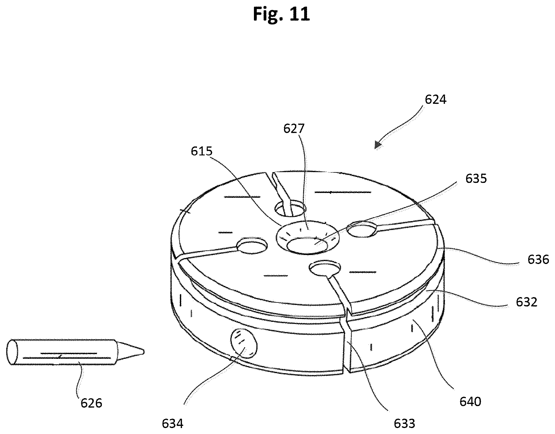
[0072] FIGS. 11 and 12 illustrate an embodiment of a tether attachment member 624 that can be included within an anchor device as described herein. Various features described herein for tether attachment member 624 can also be included in the tether attachment members described herein for other embodiments (e.g., 124, 224, 324, 424). As described above, a locking pin 626 (shown in FIG. 11) can be used to secure a tether/suture to the tether attachment member 624 in a similar manner as described above for previous embodiments.
[0073] The tether attachment member 624 is shown having a disk shape and can include a base member 640 that defines a winding channel 632, an axial tether passageway 635, radial channels 633, and a locking pin channel 634 through which the locking pin 626 can be received. The base member 640 also defines a proximal opening 615 and a distal opening 617 each communicating with the tether passageway 835. The base member 640 can include a chamfered edge or lead-in portion 627 at the proximal opening 615, and a chamfered edge or lead-in portion 629 at the distal opening 617 to allow a suture (e.g., tether) to be easily threaded into the tether passageway 635 and reduce lateral cutting force of the tether attachment member 624 against the suture. The radial channels 633 can allow a user to quickly capture and seat a tether (not shown) that is intended to be anchored. The winding channel 632 can allow a user to quickly wind tether(s) around tether attachment member 624. The use of winding channel 632 with radial channel(s) 633 can allow a user to quickly anchor the tether while permitting the user to unwind and recalibrate the anchor device to adjust the tension on the tether (not shown) as appropriate for a particular use.
[0074] FIGS. 13-16 illustrate a portion of another embodiment of an epicardial anchor device 700. The epicardial anchor device 700 includes a tether attachment member 724 and a flexible pad or fabric member (not shown in FIGS. 13-16). The tether attachment member 724 includes a base member 740 that defines a locking pin channel 734 that can receive therein a locking pin 726 in a similar manner as described above for previous embodiments and a circumferential pad channel 742. The pad channel 742 can be used to secure the flexible pad or fabric member (not shown in FIGS. 13-16) of the epicardial anchor device 700 to the tether attachment member 724. For example, the flexible pad can be disposed on a distal end portion of the tether attachment member 724 such that when the anchor device 700 is secured to a ventricular wall as described above for previous embodiments, the flexible pad contacts the ventricular wall.
[0075] The tether attachment member 724 also defines tether passageway 735 through which a tether 728 (see, e.g., FIGS. 15 and 16) can be received, and a proximal opening 715 and a distal opening 717 each in communication with the tether passageway 735. A chamfered edge or lead-in portion 729 is included at or near the distal opening 717 to allow a tether 728 (see e.g., FIGS. 15 and 16) to be easily threaded into the tether passageway 735 and reduce lateral cutting force of the tether attachment member 724 against the tether 728.
[0076] A lever arm 738 is coupled to the base member 740 that collectively with the base member 740 defines a tether passageway 735. The lever arm 738 can be moved between a first position, as shown in FIG. 16, in which the lever arm 738 is biased by a spring member 739 into a down position, and a second position, as shown in FIGS. 13-15, in which the lever arm 738 is placed in an extended position to allow the tether 728 to be placed within the tether passageway 735. For example, the lever arm 738 can be rotated in the direction of arrow A shown in FIG. 15 to move the lever arm 738 to its second or extended position. In some cases, a suture or cord can be used to pull the lever arm 738 to the extended second position.
[0077] When in the first position, as shown, for example, in FIGS. 14 and 15, a tip of the locking pin 726 is disposed at a spaced distance from the lever arm 738 and the tether passageway 735. When the locking pin 726 is spaced from the tether passageway 735, the tether 728 can be inserted into the tether passageway 735 as shown in FIG. 15. The tether 728 can then be tightened to a desired tension and the lever arm can then be released such that it is biased back to the first position, as shown in FIG. 16. When the lever arm 738 is moved (e.g., biased) to the first position, and with the tether 728 extending through the tether passageway 735, the locking pin 726 pierces or intersects with the tether 728 and the tip of the locking pin is then disposed within a cavity 736 defined by the lever arm 738 securing the tether 728 to the tether attachment member 724.
[0078] FIGS. 17-21 illustrate a portion of another embodiment of an epicardial anchor device 800 that includes a tether attachment member 824 and a flexible pad or fabric member (not shown in FIGS. 17-21). The tether attachment member 824 includes a base member 840 and a lever arm 838 pivotally coupled to the base member 840. The base member 840 defines a circumferential pad channel 842 in which the flexible pad can be coupled to the tether attachment member 824. For example, the flexible pad can be disposed on a distal end portion of the tether attachment member 824 such that when the anchor device 800 is secured to a ventricular wall as described above for previous embodiments, the flexible pad contacts the ventricular wall.
[0079] The lever arm 838 and the base member 840 collectively define a tether passageway 835 through which a tether 828 can be received, as shown in FIG. 17. The base member 840 also defines a distal opening 817 and an opening 815 each in fluid communication with the tether passageway 835. The tether 828 can be inserted through the distal opening 817 (the side to be implanted closest to the ventricular wall) and extend through a portion of the tether passageway 835 defined by the base member 840, and through a portion of the tether passageway 835 defined by the lever arm 838, and exit the opening 815. As with previous embodiments, the base member 840 includes a chamfered edge or lead-in portion 829 at the distal opening 817 of the tether passageway 835 to allow the tether 828 to be easily threaded into the tether passageway 835 and reduce lateral cutting force of the tether attachment member 824 against the tether 828.
[0080] The lever arm 838 defines a locking pin channel 844 in which a locking pin 826 can be movably disposed. The locking pin 826 includes a driver portion 846 and a piercing portion 849. As shown in FIGS. 17 and 18, the locking pin channel 844 includes portions with varying diameters in which the driver portion 846 of the locking pin 826 can be movably disposed. For example, the driver portion 846 can be threadably coupled to the inner walls of the locking pin channel 844 such that the locking pin 826 can be moved between a first position, shown in FIG. 17, in which the driver portion 846 is disposed within a portion 839 of the locking pin channel 844 and the piercing portion 849 is spaced from the tether passageway 835, and a second position in which the driver portion 846 is disposed within a portion 845 (shown in FIGS. 17 and 18) of the locking pin channel 834, and the piercing portion 849 extends through the tether passageway 835, engaging or piercing the tether 828. The lever arm 838 also defines an opening 847 that communicates with the locking pin channel 844 and can receive a driving tool that can be used to move the locking pin 826 within the locking pin channel 844 as described in more detail below.
[0081] The lever arm 838 can be moved (e.g., rotated, pivoted) between a first or open position, as shown, for example, in FIGS. 17 and 18, in which the lever arm 838 extends in a proximal direction from the base member 840, and a second or closed position as shown in FIG. 21, in which a proximal surface 819 of the lever arm 838 is substantially flush with a proximal surface 821 of the base member 840. When the lever arm 838 is in the first or open position, a delivery tool 848 can be coupled to the lever arm 828 as shown in FIGS. 19 and 20. The delivery tool 848 can include a driver 849 shown in FIG. 18 (e.g., a screw driver) that can engage the driver portion 846 of the locking pin 826 to move the locking pin 826 within the locking pin channel 834.
[0082] In operation, the tether 828 can be inserted into the tether passageway 835 and extend out of the opening 815 and within the delivery tool 848. The tether 828 can then be tightened to a desired tension. With the tether 828 at the desired tension, the driver 849 of the delivery tool 848 can then move the locking pin 826 from the first position, as shown in FIG. 17 to the second position in which the piercing portion 849 pierces or engages the tether 828, securing the tether 828 to the tether attachment member 824. For example, the driver 849 of the delivery tool 848 can threadably move the locking pin 826 from the first position to the second position. After the tether 828 is secured to the tether attachment member 824, the delivery tool 849 can be removed and the lever arm 838 can be moved to the second or closed position as shown in FIG. 21.
[0083] FIGS. 22-30 illustrate an epicardial anchor device according to another embodiment. An epicardial anchor device 900 includes a tether attachment member 924, a pad assembly 920, a tube member 955 and a tube cover member 956. The tether attachment member 924 includes a base member 940, a hub 950, a retaining ring 952, a locking pin assembly 926, and a pin member 953. The locking pin assembly 926 includes a driver portion 946 and a piercing portion 949. The base member 940 defines a circumferential pad channel 942, a retaining channel 951 and a locking pin channel 934. The pad channel 942 can be used to couple the pad assembly 920 to the tether attachment member 924. The retaining channel 951 can receive an outer edge of the retaining ring 952, which is used to retain the hub 950 to the base member 940. The base member 940 also defines cutouts or detents 943, as shown for example, in FIGS. 23, 25 and 30.
[0084] The tube member 955 is coupled to the base member 940 and the base member 940, the hub 950 and the tube member 955 collectively define a tether passageway 935 through which a tether (not shown) can be received. The cover member 956 can be formed with a fabric material, such as for example, Dacron.RTM.. The tether channel 935 intersects the locking pin channel 934 and is in fluid communication therewith.
[0085] The pad assembly 920 includes a top pad portion 958, a bottom pad portion 959 and a filler member 957 disposed therebetween. The top pad portion 958 and the bottom pad portion 959 can each be formed with, for example, a flexible fabric material. The top pad portion 958 and the bottom pad portion 959 can each define a central opening through which the tube member 955 can pass through. A portion of the top pad portion 958 is received within the channel 942 of the base member 940 as shown, for example, in FIGS. 25-27.
[0086] An outer perimeter portion of the hub 950 is received within the retaining channel 951 such that the hub 950 can rotate relative to the base member 940 to actuate the locking pin assembly 926 as described in more detail below. As shown, for example, in FIGS. 28 and 29, the hub 950 includes arms 961 with protrusions 962. The protrusions 962 can be received within cutouts 943 of the base member 940 and act as a stop or limit to the rotation of the hub 950. The slots 963 defined by the hub 950 enable the arms 961 to flex and allow the protrusions 962 to be moved in and out of the cutouts 943. As shown, for example, in FIGS. 27 and 29 the hub 950 defines a curved channel 950 on a bottom portion of the hub 950. The curved channel 950 is asymmetrical (or spiral) and receives the driver portion 946 of the locking pin assembly 926. As the hub 950 is rotated relative to the base member 940, the hub 950 acts as a cam to move the locking pin assembly 926 linearly within the locking pin channel 934. The locking pin assembly 926 can be moved from a first position in which the piercing portion 949 is disposed outside of the tether passageway 935 as shown in FIGS. 25 and 26, and a second position in which the piercing portion 949 extends through the tether passageway 935 as shown in FIG. 27. The pin member 953 (see, e.g., FIG. 26) can be formed with a metal material that is more radio-opaque than the other components of the anchor device and thus visible to the user (e.g. physician) using conventional imaging modalities to enable the user to confirm that the locking pin assembly 926 has been fully moved to the second position.
[0087] In use, when the locking pin assembly 926 is in the first position, a tether (not shown) coupled to, for example, a prosthetic mitral valve and extending through a puncture site in the ventricular wall of a heart can be inserted through the tether passageway 935. The hub 950 can then be rotated 180 degrees to move the locking pin assembly 926 linearly within the locking pin channel 934 such that the piercing portion 949 extends through the tether passageway 935 and engages or pierces the tether, securing the tether to the tether attachment member 924. For example, when the locking pin is in the first position, the protrusions 962 of the hub 950 are each disposed within one of the cutouts 943 of the base member 940 (i.e., a first protrusion is in a first cutout, and a second protrusion is in a second cutout). The hub 950 can then be rotated 180 degrees such that the protrusions 962 are moved out of the cutouts 943 of the base member 940 and at the end of the 180 degrees the protrusions 962 are moved into the other of the cutouts 943 of the base member 940 (i.e., the first protrusion is now in the second cutout, the second protrusion is now in the first cutout).
[0088] The base member 940 can also include cutout sections 966 and define side openings 967 (see, e.g., FIGS. 22 and 23) that can be used to couple a delivery device to the epicardial anchor device 900. For example, FIG. 31 illustrates a delivery device 948 having coupling arms 968 and coupling pins (not shown) extending inwardly from the arms 968. The side openings 967 can receive the coupling pins and the cutout sections 966 can be engaged by the coupling arms 968.
[0089] While various embodiments have been described above, it should be understood that they have been presented by way of example only, and not limitation. Where methods described above indicate certain events occurring in certain order, the ordering of certain events may be modified. Additionally, certain of the events may be performed concurrently in a parallel process when possible, as well as performed sequentially as described above
[0090] Where schematics and/or embodiments described above indicate certain components arranged in certain orientations or positions, the arrangement of components may be modified. While the embodiments have been particularly shown and described, it will be understood that various changes in form and details may be made. Any portion of the apparatus and/or methods described herein may be combined in any combination, except mutually exclusive combinations. The embodiments described herein can include various combinations and/or sub-combinations of the functions, components, and/or features of the different embodiments described.
* * * * *
D00000
D00001
D00002
D00003
D00004
D00005
D00006
D00007
D00008
D00009
D00010
D00011
D00012
D00013
D00014
D00015
D00016
D00017

D00018
D00019
D00020
D00021
D00022

D00023
D00024

D00025
D00026
D00027
D00028
D00029

D00030
D00031

XML
uspto.report is an independent third-party trademark research tool that is not affiliated, endorsed, or sponsored by the United States Patent and Trademark Office (USPTO) or any other governmental organization. The information provided by uspto.report is based on publicly available data at the time of writing and is intended for informational purposes only.
While we strive to provide accurate and up-to-date information, we do not guarantee the accuracy, completeness, reliability, or suitability of the information displayed on this site. The use of this site is at your own risk. Any reliance you place on such information is therefore strictly at your own risk.
All official trademark data, including owner information, should be verified by visiting the official USPTO website at www.uspto.gov. This site is not intended to replace professional legal advice and should not be used as a substitute for consulting with a legal professional who is knowledgeable about trademark law.